
Related Manuals for Teknatool nova Neptune DVR


Summary of Contents for Teknatool nova Neptune DVR
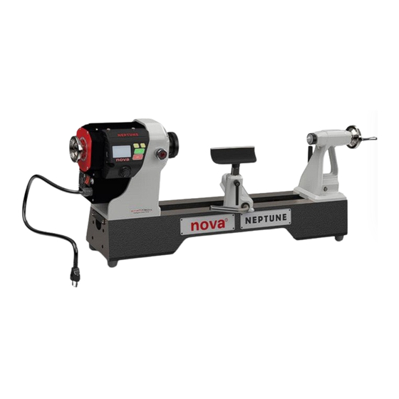
- Page 1 Neptune DVR 15” LATHE USA & Canada SKU: 55700 New Zealand & Australia SKU: 55701 UK SKU: 55702 Europe SKU: 55703...
-
Page 2: Contact
For all worldwide Inquiries, Repairs or Services (issues must be in writing) Contact us at: https://www.teknatool.com/support/ Or you can contact the retailer where you purchased your NOVA Neptune DVR 15” DVR Lathe, for contact details please see our website www.teknatool.com... -
Page 3: Table Of Contents
Table of Contents Contact ..................................2 Table of Contents ...............................3 1.General Safety Rules ...............................4 2.NOVA Neptune DVR 15” DVR Lathe Features & Specification ...................5 3.Shipping Contents ..............................7 4.Setup and Assembling the Lathe ..........................8 4.1 Unpacking and Preparing the Lathe ........................9 4.2 Lathe Installation .............................9 4.2.1 Install the feet to the bed ..........................9... -
Page 4: General Safety Rules
1.General Safety Rules WARNING Failure to follow these rules may result in serious personal injury or death. ❖ IMPORTANT: Before switching the lathe on, ALWAYS check the machine for the correct setting and speed BEFORE OPERATING THE TOOL READ THE KEEP GUARDS IN PLACE and in working order. -
Page 5: Nova Neptune Dvr 15" Dvr Lathe Features & Specification
NOVA Neptune DVR 15” DVR Lathe Features & Specification Feature Name Description The DVR motor uses smart motor technology to provide an incredibly smooth DIGITAL VARIABLE and powerful direct drive. The controller constantly monitors the spindle RELUCTANCE (DVR) position and maintains optimal spindle speed. Additional power is added as it ELECTRONIC DRIVE senses extra load from the tool. - Page 6 Lathe Specifications Metric Imperial Swing Over Bed 381 mm 15” Distance Between Centres 457 mm 18” Overall Size 840mm (L) x 425mm (w) x 380mm(H) 33” (L) x 16.7” (w) x 15” (H) Package Size 900mm (L) x 485mm (w) x 440mm (H) 35.4”...
-
Page 7: Shipping Contents
3.Shipping Contents ITEM NUMBERS DESCRIPTION Headstock Assembly (+HMI) 5529013 Tool slide Assembly 5529011 Tailstock Assembly 5529012 Main Bed 5529123 Bed End Stopper Plate 5569059 Stopper Plate Screws M5 x 6mm MPB0506 Locking Handle – M10 x 20mm Locking Handle – M8 x 20mm Nova 6"... -
Page 8: Setup And Assembling The Lathe
4.Setup and Assembling the Lathe Workshop Environment Your workshop should set up appropriately for you to effectively use the lathe. The workshop should be setup with the following factors taken into consideration: Lathe location Locate the NOVA 15” lathe close to a power source in an area with good amount of lighting. Leave enough clearance when the lathe headstock is swiveled around. -
Page 9: Unpacking And Preparing The Lathe
4.1 Unpacking and Preparing the Lathe 1. Remove all smaller items from main carton. Do not discard carton or packing material until the lathe is assembled and running satisfactorily. 2. Inspect contents for shipping damage; if any is found, report it to your distributor. 3. -
Page 10: Assemble The Toolrest And Tailstock
4.2.2 Assemble the Toolrest and Tailstock Assemble the Toolrest post Assemble the tailstock 4.2.3 Mounting the Headstock, Toolrest and Tailstock onto the Bed 1. Slide headstock, Toolrest, and tailstock onto bed, ensuring lock plate (A) is correctly lined up with bed way (B), as shown below: 128-01-2305 128-0621-003... - Page 11 Note: Turn the lock handle to adjust the position of the lock plate if they cannot slide onto the lathe bed section. 2. Replace stop plates on both ends of bed. Screw end plate into bed to secure headstock onto bed Screw end plate into bed to secure tailstock onto bed 128-01-2305 128-0621-003...
-
Page 12: Positioning The Headstock On The Bed
4.3 Positioning the Headstock on the Bed The headstock uses a cam lock assembly for securing in place along the bed. To move the headstock: 1. To unlock the headstock, push the locking handle backwards or lock the headstock by pushing the handle forwards. - Page 13 4.4 Spindle Index/Lock The spindle index pin locks the headstock spindle. It is selectable in 15-degree increments (24 divisions). An indicator decal is on the rear headstock. 1. Stop the lathe. 2. To lock the spindle, lift up and turn the Locking Knob into the LOCK position until the internal pin engaged into the index fly wheel.
-
Page 14: Tailstock
4.5 Toolrest Loosen the Toolslide clamp Handle counterclockwise, move the tool slide to the desired position, and tighten the clamp handle clockwise. Adjust the Toolrest close to the work piece. Exact positioning may be varied to suit the turner. Revolve the stock by hand to make sure it clears the rest before starting the lathe.At intervals, stop the lathe and readjust the Toolrest. - Page 15 Double ended 2 Morse Taper method: a. Lock the Headstock at 0° by using the locking handle on the bed. Slide toolrest up against the headstock. b. Loosen the motor mounting screws on the headstock, approximately 5-8 turns should be acceptable.
- Page 16 flange sits securely against the inner ring of the headstock. e. Tighten the motor mounting screws against the headstock, tightening the screws in a diagonally opposite sequence. Remove the double ended morse taper from the headstock and tailstock (use a knockout bar if required).
-
Page 17: Mounting A Faceplate Or A Chuck
4.8 Mounting a Faceplate or a Chuck The thread size of headstock Spindle is 1.25" RH (Standard version), or M33 RH (Euro version), depending on your model. 1 ¼” Standard version spindle Euro version spindle 4.8.1 Mounting on the Standard Version Spindle Make sure there is no gap between faceplate Use the Spindle Index Pin to lock the headstock spindle before commencing. -
Page 18: Connecting To Power
5. Connecting to Power Warning! Improper power connection may result in a risk of electrical hazard. Before plugging the NOVA lathe into the power source, check that the: 1. The main power switch is turned off. 2. Power source is switched off. Note: This image on the left-hand side is the European version of the NOVA wood lathe. -
Page 19: Ground Fault Interrupters (Gfi)
5.1 Ground Fault Interrupters (GFI) For a GFI to be compatible with the DVR motor, it is recommended have a leak current threshold rating of 30mA (0.03A) Note: Normal household GFI will typically be rated at 5mA (0.005A) which may trigger during the operation of the DVR motor. -
Page 20: Lathe Operation On Hmi Panel - Human Machine Interface Panel
6. Lathe Operation on HMI Panel - Human Machine Interface Panel 6.1 HMI introduction The Neptune HMI panel consists of four keys, one speed knob for the lathe operation, the 2.4” LCD shows the status of the lathe in real time, these keys and icons on the panel are illustrated as follows. [FUNC]: Access or Exit to the lathe functions. -
Page 21: General Hmi Operations
6.2 General HMI operations 6.2.1 Start-Up Turn on the switch, the HMI will run the self-test in 3 seconds. During the test, the LCD will show all icons and software version No. before it goes to the Home page. At the home page, the machine is ready to run now, the default speed is 100 RPM. - Page 22 6.2.5 Speed knob The speed knob has two functions: Speed control, Select & Confirm in FUNC. • Fine speed Control - +/-5 RPM by Turning it in clockwise or counter-clockwise while the LCD is on the Home Page or the Motor Running. •...
- Page 23 6.3.3 Favourite speed The HMI is built in four favourite speeds for a quick start-up. To use, change and save the settings, follow the instructions as follows. While the motor is running or stop: Step1 :Press [FUNC] once on the Home page and then press [ON] to enter the Favourite Speed page, turn the speed knob to select pre-set speed slot number, press [ON] to confirm or press [FUNC] or [OFF] to exit.
- Page 24 6.3.5 Speed chart for Rough cut The speed chart is a recommend, editable speed guide/reference according to the diameters of the wood and type of turning. It’s accessible whenever the motor is running or stop: Step1: Press [FUNC] once on the Home page, turn the speed knob to Rough cut icon, and then press [ON] to enter the Rough cut page or press [FUNC] or [OFF] to exit.
- Page 25 6.3.7 XL/Unbalanced Mode The HMI offers smart speed profiles for XL/Unbalanced turning operation, such as slow starting up, steady and smooth speed acceleration for unbalance wood piece, the mode is ONLY accessible when the motor is stopped, the default setting is OFF. Step1: Press [FUNC] once on the Home page, turn the speed knob to XL/Unbalanced icon, and then press [ON] to enter the XL/Unbalanced page as below or press [FUNC] or [OFF] to exit.
- Page 26 Stop the motor first, press [Down & Hold] speed knob +[FUNC] for 3second. The HMI enters the USB mode for firmware upgrade. Download HMI USB/DFU update software and firmware from the website: www. teknatool.com, follow the instructions to upgrade HMI firmware.
-
Page 27: Maintenance
7. Maintenance • WARNING Improper power connection may result in a risk of electrical hazard Regular maintenance is essential when considering the long-term use of the lathe. Maintenance After Each Use 1. Clean the work area and lathe. 2. Vacuum shavings and dust from the headstock, table and base. Monthly Maintenance 1. -
Page 28: Troubleshooting
8. Troubleshooting 8.1 Mechanical Issues SYMPTOM PLACE TO CHECK HOW TO RESOLVE 1. Remove any work pieces/tools attached to the headstock, inspect if there is any foreign materials or damages to the threads. ▪ Work attached to the lathe 2. Attach the tools one at a time to check which part is Excessive Vibration ▪... -
Page 29: Teknatool Warranty
Our policy is one of continuous improvement. We therefore reserve the right to change specification/design without notice. This warranty is Teknatool International Ltd and Teknatool USA Inc. sole warranty whether written or verbal, whether expressed or implied by law, trade, custom, or otherwise, whether of merchantability, fitness for purpose, or otherwise, except for remedies available to customers under the Consumer Guarantees Act or other legislation. -
Page 30: Nova Dvr Lathe Breakdown
10. NOVA DVR Lathe Breakdown NOVA DVR Headstock Breakdown 128-01-2305 128-0621-003... - Page 31 NOVA DVR Tailstock Breakdown 128-01-2305 128-0621-003...
- Page 32 NOVA DVR Toolrest Breakdown NOVA DVR Bed Breakdown 128-01-2305 128-0621-003...
-
Page 33: Nova Dvr Lathe Parts List
11. NOVA DVR Lathe Parts List ITEM ITEM DESCRIPTION QTY. DESCRIPTION QTY. Headstock Assembly 5529013 Main Assembly Headstock 5529127 Main Bed 5529123 Controller assembly 5529015 Feet Assembly 5529146 End Stopper Plate 5569059 Motor assembly 5529016 Stopper Plate Screws M5 x 6 MPB0506 Spindle Lock screw 5529121... -
Page 34: Nova Dvr Wiring Diagram
12. NOVA DVR Wiring Diagram 128-01-2305 128-0621-003... - Page 35 Due to NOVA’s continuous product improvement and development policy, specifications, features and images contained in this manual may change without notice. Teknatool is not responsible for omissions or errors herein, or for incidental damages in connection with the furnishing of this information.
Need help?
Do you have a question about the nova Neptune DVR and is the answer not in the manual?
Questions and answers