Table of Contents
Advertisement
Advertisement
Table of Contents

Related Manuals for Kongsberg Simrad Robertson AP300X Series


Summary of Contents for Kongsberg Simrad Robertson AP300X Series
- Page 2 NOTE! Simrad Robertson AS makes every effort to ensure that the information contained within this document is correct. However, our equipment is continuously being improved and updated, so we cannot assume liability for any errors which may occur. The information contained within this document remains the sole property of Simrad Robertson AS.
- Page 3 Instruction Manual Instruction Manual This manual is intended as a reference guide for operating and correctly installing the AP300X autopilot. Great care has been paid to simplify operation and set-up of the Robertson AP300X, however, an autopilot is a complex electronic system. It is affected by sea conditions, speed of the vessel, hull shape and size.
- Page 4 Robertson AP300X Autopilot Document revisions Date Written by Checked by Approved by – 08.04.1994 Th.H. 03.05.1994 Th.H. 27.09.1994 Th.H. 24.11.1994 Th.H. 10.02.1995 Th.H. 06.11.1995 Th.H. 17.01.1996 Th.H. 28.08.1996 Th.H. 25.02.1997 Th.H. Document history Rev. Action/Changes/References – Original issue. Change of cable clamp in junction units page 71. Minor corrections in text and displays.
-
Page 5: Table Of Contents
Instruction Manual Contents GENERAL INFORMATION................... 9 Introduction ......................9 How to use this manual ..................10 System components ..................... 10 AP300CX Control unit..................11 AP300PX Control Unit ..................11 AP300DLX Control Unit ..................11 J300X, J300X-40 and J3000X Junction Units ............12 RF300 Rudder Feedback unit ................ - Page 6 Robertson AP300X Autopilot Non-Follow-Up steering ..................22 NFU Steering lever....................22 R3000X Remote Control ..................24 Automatic Steering ....................24 Dodging......................... 24 U-Turn ........................26 Tacking in Auto mode..................26 Navigating with the AP300X................27 Selecting a different Navigator ................28 Dodging in Nav.
- Page 7 Instruction Manual 2.15 Navigating with the AP300DLX ................ 54 Navigating to a Temporary waypoint .............. 55 Navigating to a stored waypoint ............... 56 Arriving at a waypoint..................57 Plotting with the AP300DLX ................58 Navigating through a route................59 Navigating using the MOB function ..............61 MOB (Man over Board)..................
- Page 8 Robertson AP300X Autopilot Databox/J3000X ....................85 Databox/J300X ..................... 86 Radar Clock/Data....................86 DATALINE Instrument installation..............86 External Alarm ..................... 87 NI300X NMEA Interface Unit ................87 LF3000 Linear Feedback..................88 CI300X Analogue Interface Unit ................ 90 CD100 Course Detector ..................92 CDI35 Interface.....................
- Page 9 Instruction Manual Compass ......................111 Drive unit ......................111 Exchange of EPROMS ..................112 TROUBLE SHOOTING ....................114 Alarms ......................... 114 NMEA Test........................117 System Data Menu ..................... 118 TECHNICAL SPECIFICATIONS ................119 AP300X Autopilot System ................119 Control Units (AP300CX, AP300PX, AP300DLX).......... 120 Junction units......................
- Page 10 Robertson AP300X Autopilot 22081814H...
-
Page 11: General Information
General Information 1 GENERAL INFORMATION 1.1 Introduction Congratulations on the purchase of your new Robertson AP300X autopilot system and thank you for selecting what we feel is the most advanced autopilot system available on the market today. Simrad Robertson AS is located in Egersund on the south/west coast of Norway. -
Page 12: How To Use This Manual
Robertson AP300X Autopilot 1.2 How to use this manual This manual is intended as a reference guide for operating, installing and maintaining the AP300X series of autopilots. Great care has been paid to simplify operation and set-up of the Robertson AP300X, however, an autopilot is a complex electronic system. -
Page 13: Ap300Cx Control Unit
General Information AP300CX Control unit A compact autopilot control for panel, bulkhead or bracket mounting. Large LCD display for readout of autopilot data and rotary course selector. It has three Robnet connectors for system inter- connection and expansion. Weight: 0,4 kg (0,9 lbs) AP300PX Control Unit Portable control unit with 7 m (20 ft.) of cable. -
Page 14: J300X, J300X-40 And J3000X Junction Units
Robertson AP300X Autopilot • Plot function • Full feature demo and training software • 100 waypoints and 20 routes memory capacity J300X, J300X-40 and J3000X Junction Units J300X J3000X Weight: 1,3kg (2,9 lbs.) J300X-40 Weight: 2,8kg (6,2 lbs.) The junction unit is the central unit in the AP300X autopilot system. It contains the steering computer, interface circuits to all system components and drive circuits for the drive unit motor and clutch. -
Page 15: Rf300 Rudder Feedback Unit
General Information RF300 Rudder Feedback unit Weight: 0,5 kg (1,1 lbs) Rudder feedback unit with transmission link and 10 m (30 feet) of cable. Transforms the angular travel of the rudder to a digital signal read by the autopilot steering computer. 22081814H... -
Page 16: Rfc35 Electronic Fluxgate Compass
Robertson AP300X Autopilot RFC35 Electronic fluxgate compass Weight: 0,9 kg (2,0 lbs) A new compact heading sensor from Robertson with 15 m (45 feet) of cable. The direction of the earth's magnetic field is sensed by a floating ring core in a fluxgate coil and transformed to a digital signal read by the autopilot steering computer. -
Page 17: Rudder" Indicator
General Information Rudder" indicator Dataline 110mm 50mm Dia. Weight: 0,2 kg (0,4 lbs) Function Light 110mm 17mm 18mm A Robertson Dataline instrument that can be connected directly to one of the AP300X NMEA outputs. Analogue display of boat's rudder angle. Compass"... -
Page 18: Lf3000 Linear Feedback
Robertson AP300X Autopilot LF3000 Linear Feedback Linear feedback unit for boats with outboard engine. Transforms the linear movement to an analogue signal. Supplied with 8,5 m cable and mounting clamps. Weight: 0,8 kg (1,8 lbs) LFI3000 Linear Feedback Interface Interface unit for LF3000 Linear Feedback. Converts the analogue LF3000 signal to the standard digital feedback signal for the autopilot steering computer. -
Page 19: R3000X Remote Control
General Information R3000X Remote Control A small handheld remote control with two push buttons for power steering or course selection (port and starboard) and one push button with built-in lighted indicator for mode selection. Weight: 0,4 kg (0,9 lbs.) S100 NFU steering lever Designed for in-door console mount. -
Page 20: Jp300 Jack Point
Robertson AP300X Autopilot JP300 Jack Point Jack point for remote connection of AP300PX. Robnet male connector and 0.5 m cable with female connector daisy chain connection. Mounting brackets Optional mounting bracket AP300CX and AP300DLX. Top mount bezel Optional bezel for panel Optional bezel for panel top mount top mount of AP300CX of AP300DLX. -
Page 21: Ap300X Autopilot Operation
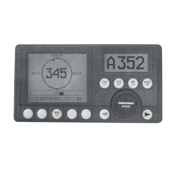
Autopilot Operation 2 AP300X AUTOPILOT OPERATION An autopilot is a very useful navigational aid, but DOES NOT under Caution ! any circumstance replace a human navigator. Do not use automatic steering when: • In heavy traffic areas or in narrow waters •... - Page 22 Robertson AP300X Autopilot AP300CX CONTROL UNIT STBY (Standby) Push Button Autopilot LCD display Turns the autopilot ON/OFF Heading (STBY mode) STBY Selects STBY mode Set Course (AUTO mode) Enables/disables lock function XTE (NAV mode) Wind angle (WIND mode) STBY AUTO NAV.
-
Page 23: Ap300X With Msd50 Stern Drive Unit
Autopilot Operation 2.2 AP300X with MSD50 Stern Drive unit The information on this page applies if your autopilot is driving a Robertson Note ! MSD50 Stern Drive. The MSD50 Stern Drive unit has a relative feedback signal which needs a zero point setting after the autopilot has been turned on. Refer to page 1-1 of the MSD50 manual for further information. -
Page 24: On/Off / Standby Mode
Robertson AP300X Autopilot 2.3 ON/OFF / Standby mode A single press on the STBY button switches the system ON and the following status displays are shown * Robertson * Autopilot model * AP300X * SW V1R12 Software V(ersion) and R(elease) HW rev. - Page 25 Autopilot Operation Standby Mode Operation Primary Display First Press S265 STBY Current heading Secondary Display Second Press STBY STBY Rudder angle (PORT 7 degrees) Follow Up Steering Press both buttons simultaneously to Commanded rudder angle activate Follow-Up Use course dial to command rudder angle Robertson WARNING:...
-
Page 26: R3000X Remote Control
Robertson AP300X Autopilot R3000X Remote Control When AUTO mode, Note ! REMOTE pressing buttons will change the set course 1 ° per Push buttons for Port and Stbd NFU commands push. If you keep the button pressed, it will automatically change course STBY-AUTO... - Page 27 Autopilot Operation Automatic Mode Operation (Automatic steering by compass input only) First Press A265 Regain manual AUTO STBY steering by SPEED pressing: Set course Course adjust Course change 1 degree/push Increase Robertson CCW: Decrease Decrease Increase Second Press HI speed parameters AUTO selected SPEED...
-
Page 28: U-Turn
Robertson AP300X Autopilot When in DODGE mode the course displayed is the current boat's heading, however the previous set course is remembered by the AP300X. When DODGE is displayed, the AP300X is no longer in control of the steering, and you must either manually steer the boat or take control using either Non Follow Up steering or Follow Up steering. -
Page 29: Navigating With The Ap300X
Autopilot Operation 2.5 Navigating with the AP300X The AP300X has the capability to use steering information from an external navigator (GPS, LORAN, Decca) or the NAV. computer in AP300DLX to direct the boat to a specific waypoint location, or through a route of waypoints. In the NAV mode, the AP300X uses the heading sensor as it's primary source of heading for course keeping. -
Page 30: Selecting A Different Navigator
Robertson AP300X Autopilot Navigation Mode Operation (Automatic steering by compass and Nav source input) First Press WP: WP 001 Waypoint Name Brg. Bearing WP-WP (leg) SETUP Chg. Required course change OK:? Press NAV If required course change is safe, press NAV to accept Second press .02 Nm XTE Display... -
Page 31: Dodging In Nav. Mode
Autopilot Operation If the AP300X is connected to a Nav. receiver that does not transmit a Note ! message with bearing to next waypoint, it will pick a XTE message and steer on Cross Track Error only. In that case you have to revert to AUTO mode at each waypoint and manually change set course to equal bearing to next waypoint and then select NAV mode again. - Page 32 Robertson AP300X Autopilot Dodging while in the WIND mode is very similar to dodging while in the AUTO or NAV modes. Refer to DODGE mode operation in the AUTO mode section on page 24. Wind Vane Steering Operation (Automatic steering by compass and wind vane) First Press Regain manual STBY...
-
Page 33: Tacking In Wind Mode
Autopilot Operation Tacking in Wind mode In WIND mode on sailboats there is also a tacking aid function. This function may only be used when the boat is reaching and will when activated take the boat from the course you are steering to the computed course that gives you the same apparent wind on the other side. -
Page 34: Manual Speed Selection
Robertson AP300X Autopilot Manual speed selection Select AUTO mode. Press the AUTO button a second time to display the secondary AUTO display. To toggle between HI and LO speed parameters, press the "AUTO" button two times quickly. If you change boat speed it is recommended that you select HI or LO parameters correspondingly Quick double press AUTO... - Page 35 Autopilot Operation Inactive S265 The “Lock” function is disengaged by the following STBY actions: DODGE TURN • The “active” control unit unlocks by a double press on the STBY button. • The system is switched OFF by any control unit STBY (press STBY for 3-5 seconds).
-
Page 36: The User Set-Up Menu
Robertson AP300X Autopilot 2.10 The User Set-up Menu Quick double press Sequences - SETUP - FWD in MENU Backlight Robertson SETUP SETUP BACK Sequences Displays User Enter User Scrolls through menu BACK in MENU Set-up Menu Setup Menu selections or sets value on menu items Adjusts backlight of display and pushbuttons in 10 steps. -
Page 37: Ap300Dlx Main Features
Autopilot Operation 2.11 AP300DLX Main features Graphic Display Section Autopilot Section Route Display - Rudder Angle .02 Nm Library Heading Speed Distance Waypoint Water Temp. storage-bank Engine hours (98 user input Wind waypoints) Position Waypoint info Route info UTC time Navigation Local time Computer... -
Page 38: Availability Of Data Sources
Robertson AP300X Autopilot − Navigate directly to any previously stored waypoint or to a temporary waypoint − Navigate through any route of waypoints stored in memory (forward or reverse) − A unique "skip" feature to enable changing the next waypoint when following a route −... -
Page 39: Operation Of Graphic Display
Autopilot Operation 2.12 Operation of Graphic Display The AP300DLX Control Unit has an extra graphic LCD display. Controlled by the five push buttons under the display and autopilot controls, it can be programmed to show various information or to do navigation calculations and store waypoints and routes. -
Page 40: Graphic Display Setup
Robertson AP300X Autopilot The AP300DLX can access up to six different NMEA inputs and has control for selecting which position source to use (one or two NMEA inputs are standard dependent on the type of junction unit installed, 4 additional with optional NI300X. Incoming data is checked for status and selected sentences of data from the selected position source are also retransmitted on all NMEA outputs. -
Page 41: Plot Interval
Autopilot Operation Plot interval When using the Plot screen, you can determine how often you want to mark your position on the plot. In addition to no position marking, the following time intervals are available: 1 - 10 - 30 and 60 minutes. INFO PLOT INSTR... -
Page 42: Position Calibration
Robertson AP300X Autopilot If you select the LOCAL TIME menu item and then press ENTER, the following display will appear provided a sentence containing the UTC message is available at the NMEA input(s): UTC TIME LOCAL TIME 07 40 ENTER MAIN Use –... -
Page 43: Automatic Magvar Calculation
Autopilot Operation To input or change a position from the main menu: PLOT INSTR INFO SETUP ROUTE WAYPT GOTO MAIN MAIN ENTER to select "Position Correction" and press ENTER. Indicates that GPS 1 POSITION position is corrected 58°27.00' Position from Nav. -
Page 44: Manual Input Of Magvar
Robertson AP300X Autopilot If the system includes a Robertson gyrocompass, the AP300DLX does not use the MAGVAR value when Gyro is selected as the current heading sensor. COG and bearings will then be displayed as TRUE values, designated by the letter "T". To view the current MAGVAR calculation method and MAGVAR value: INFO... - Page 45 Autopilot Operation Magnetic Variation West MANUAL ENTER MAIN EAST WEST Change Magnetic Save magnetic Return SETUP to Variation 1 deg./push variation and previous menu leave MENU. without changing MAGVAR To input 4° of westerly variation, press the WEST key 4 times, then press ENTER Leave the menu by pressing ESC or MAIN.
-
Page 46: Clearing Waypoint Database
Robertson AP300X Autopilot Clearing Waypoint Database Clearing the Waypoint Database memory will wipe out all waypoint names, Note ! waypoint positions, and routes. If a single waypoint or small number of waypoints need to be changed or deleted, it is better to use the EDIT WAYPOINTS feature. -
Page 47: Displays And Menu Structure
Autopilot Operation Displays and menu structure The following display is presented approximately 5 seconds after the AP300DLX is turned on: NORTH MAIN SCREEN WEST EAST PORT STBD Select PLOT INSTR MOB INFO X-Y plotter Select Instruments: Memorize present Enter Nav-Computer Compass Heading position as "Man Mode for navigation to... -
Page 48: Info And Pos Screens
Robertson AP300X Autopilot INFO and POS screens The following display is accessed from the main menu by pressing the INFO softkey: Position DGPS 1 POSITION source (D denotes differential GPS) 58°27.00' Own ship's present position 05°58.30' Course & speed over ground COG : 000°... -
Page 49: Instrument Displays And Menu
Autopilot Operation Instrument displays and menu The complete menu of instrument screens is shown below. The order of appearance of the displays below the Heading Screen may vary. Press NEXT, if necessary, to find the screen you are looking for. MAIN SCREEN HEADING SCREEN NORTH... -
Page 50: Waypoints
Robertson AP300X Autopilot 2.13 Waypoints A waypoint is any position that you want to navigate to. It can be a buoy, the entrance to an inlet, a favorite wreck location, or an intermediate turning point 300 miles out in the ocean. Three different types of waypoints are available in the AP300DLX navigator: Stored waypoints (98 are available), Temporary Waypoint (1 is... - Page 51 Autopilot Operation The accuracy of current navigation systems make it possible to WARNING ! automatically navigate extremely close to positions that you will input the AP300DLX. When entering waypoints from a nautical chart or from a position listing, select a position that is a safe distance away from the actual location, to insure that you will not steer directly into e.g.a selected buoy.
- Page 52 Robertson AP300X Autopilot Saving Present Position to a Waypoint NORTH WEST EAST GPS1 POSITION PORT STBD 40°52.60' 72°30.15' PLOT INSTR INFO Select WP MOB - WP COG : 075°M SOG : 5.00Kt TEMP - WP Selected Buoy - 002 Waypoint XXXX - 003 XXXX - 004 Buoy32a...
- Page 53 Autopilot Operation Editing Waypoints Editing allows you to change the Name, NORTH Latitude or Longitude value of a waypoint. Waypoints may be edited (changed) or deleted (erased). WEST EAST GPS1 POSITION PORT STBD 40°52.60' 72°30.15' PLOT INSTR MOB INFO COG : 075°M SOG : 5.00Kt SETUP...
-
Page 54: Routes
Robertson AP300X Autopilot 2.14 Routes A route is composed of a number of waypoints that are already stored in the AP300DLX waypoint memory. The route system provides flexibility with a simple approach to adding, inserting, deleting waypoints in any of the routes. The AP300DLX provides the ability to build up to 20 different routes and store the routes into memory. - Page 55 Autopilot Operation • Adding from the prevoiusly stored waypoints to the route list. • Pressing "Enter" after creating the complete route. The MOB waypoint and TEMP-WP may not be used as part of a route. Note ! NORTH GPS1 POSITION WEST EAST 40°52.60'...
-
Page 56: Correction Of Routes
Robertson AP300X Autopilot Continue adding waypoints to the new route until you have created the complete route. Then press ENTER to save the route Correction of routes Deleting waypoints from the route list does not affect the listing of the waypoints in the waypoint memory. -
Page 57: Navigating To A Temporary Waypoint
Autopilot Operation Navigating to a Temporary waypoint The temporary waypoint feature in the AP300DLX is a simple method to navigate to a location without storing the location permanently. Each time you select the TEMP -WP function, the new position that you input will over-write the previous TEMP-WP position. -
Page 58: Navigating To A Stored Waypoint
Robertson AP300X Autopilot Navigating to a stored waypoint NORTH GPS 1 POSITION GPS 1 POSITION 40°52.60' 40°52.60' 72°30.15' 72°30.15' WEST EAST COG: 075°M SOG: 5.00Kt COG: 075°M SOG: 5.00Kt PORT STBD Destination: SETUP ROUTE MAIN WAYPT GOTO TEMP MAIN ROUTE WAYPT INFO PLOT INSTR... -
Page 59: Arriving At A Waypoint
Autopilot Operation Arriving at a waypoint The AP300DLX uses one of the following criteria to determine that you have arrived at a waypoint: • When you are within 30 seconds of arriving at the waypoint. This is determined by the speed of the boat (provided by the speed over ground data), and the distance to the waypoint. -
Page 60: Plotting With The Ap300Dlx
Robertson AP300X Autopilot Plotting with the AP300DLX Plot mode presents a temporary track plot of the ship's movement. Each time you access the PLOT NORTH mode, the screen is re-drawn with the boat's current position in the center of the screen. EAST WEST If a waypoint is active in the AP300DLX, the ship's... -
Page 61: Navigating Through A Route
Autopilot Operation Navigating through a route When you select the route screen, you are presented with a list of all of the available routes stored in the AP300DLX memory. The pointer (>) identifies the selected route. Turn the course dial clockwise to advance through the available routes, until you are pointing at the route name that you wish to steer to. - Page 62 Robertson AP300X Autopilot The process that the AP300DLX sequences through waypoints in a route is done automatically, but the autopilot commands require operator verification before a major course change is allowed. THIS IS A SAFETY FEATURE OF THE AP300DLX! NORTH GPS 1 POSITION GPS 1 POSITION 40°52.60'...
-
Page 63: Navigating Using The Mob Function
Autopilot Operation Navigating using the MOB function The MOB function is a fast and easy method of temporarily saving present position. It is designed to be used in an emergency situation where it is critical to return to the exact location where an incident occurred. -
Page 64: Mob (Man Over Board)
Robertson AP300X Autopilot MOB (Man over Board) NORTH Press and hold MOB softkey for 5 seconds to activate MOB function. WEST EAST MOB screen shows the position and MOB POSITION PORT STBD the bearing and distance to the MOB 40°52.60' point. -
Page 65: Glossary
Autopilot Operation 2.16 Glossary ASF corrections, Loran - Additional secondary phase factor is the amount in microseconds, by which the time difference of an actual Loran signal that has traveled over varied terrain, differs from that of an ideal signal over an all-seaweather path. (ie. Loran signals travel slower over ground). - Page 66 Robertson AP300X Autopilot Waypoint - A discrete point, stored in a navigator, located on the surface of the earth. Normally this point will be identified by Lat/Lon coordinates although in some systems it may be shown by T.D.'s. The AP300DLX has the capability of storing 98 waypoints. XTE - Cross Track Error - Used to identify a vessels position relative to a straight line drawn between two waypoints.
-
Page 67: Installation
Installation 3 INSTALLATION 3.1 General This section provides detailed information required to successfully install AP300X Autopilot system The AP300X system includes several modules that need to be mounted in different locations on the boat, and also need to interface with at least three different systems on the boat: •... -
Page 68: Unpacking And Handling
Robertson AP300X Autopilot 9. Seatrial settings (Page 103) Set rudder zero Compass calibration Compass Offset adjustment Automatic tuning (Optional: does not need to be done) Viewing parameters 10. Testing Autopilot Operation at Sea (refer to Sea Trial instructions, page 109) 11. -
Page 69: Ap300X Basic System
Installation AP300X Basic system AP300CX CONTROL UNIT JUNCTION UNIT 15 m (49') REVERSIBLE PUMP MAINS POWER SUPPLY 10-40 VDC Note 15 m (49') 10 m (33') ROBNET Network Cable RFC35 ELECTRONIC FLUXGATE Other cable COMPASS RF300 RUDDER Note: 10 - 28 VDC Mains with J3000X FEEDBACK AP300X multistation system with optional drive units... -
Page 70: Ap300X System With Compass Interface Options
Robertson AP300X Autopilot AP300X system with compass interface options AP300DLX CONTROL AP300CX UNIT CI100X CONTROL COMPASS UNIT INTERFACE BOAT'S MAGNETIC COMPASS 7 m (23') 7 m (23') CDI35 RGC50 BOAT'S JUNCTION COURSE GYRO COMPASS MAGNETIC 15 m (46') UNIT DETECTOR COMPASS RPU160 INTERFACE... -
Page 71: Rf300 Rudder Feedback Installation
Installation 3.2 RF300 Rudder feedback installation The RF300 Rudder feedback unit mounts close to the rudders, and is mechanically linked to the rudder tiller arm or rudder quadrant. Refer Figure recommended mounting arrangement. Note that the RF300 transmitter arm has two slots for the transmission link. -
Page 72: Junction Unit Installation
Robertson AP300X Autopilot Due to space limitations, it may be necessary to cut the length of the Note ! transmitter rod to move the RF300 closer to the rudder post. Tighten the mounting screws for both the RF300 feedback unit and the transmitter rod ball joint. -
Page 73: Grounding And Rfi
Installation Refer to the table below for recommended cable sizes. Cable length Drive Unit Voltage 1. Distribution Board to Junction Unit. 12 V 2. Junction Unit to Drive Unit motor AWG mm AWG mm (Length refers to each of the two cables) Up to 3 m (10 ft.) Up to 6 m ( (20 ft.) -
Page 74: Drive Unit Installation
Robertson AP300X Autopilot Pull out each terminal before connecting the wires. Remove all strands before putting on the terminal cover. 3.4 Drive unit installation The relation between drive units, drive unit voltage, input voltage, drive output and interfacing to steering gear are shown in the table below. - Page 75 Installation When selecting DRIVE UNIT voltage in the Installation setup, the Note ! clutch/bypass voltage is always set equal to the motor voltage. If a retrofit installation where e.g. a HLD2000 has a 12V motor and a 24V bypass valve, the bypass valve solenoid has to be changed back to standard 12V version.
-
Page 76: Connecting A Reversible Pump
Robertson AP300X Autopilot Connecting a reversible pump JUNCTION UNIT POWER PCB TB1 TB2 TB3 TB4 TB5 Robertson reversible pump Connecting a hydraulic linear drive HYDRAULIC JUNCTION UNIT LINEAR DRIVE POWER PCB TB1 TB2 TB3 TB4 TB5 Bypass Clutch Single pole clutch/bypass switch Connecting a solenoid valve... -
Page 77: Control Unit Installation
Installation 3.5 Control unit installation Avoid mounting the control unit(s) where it is easily exposed to sunlight, as this will shorten the lifetime of the displays. If this is not possible, make sure the units are always covered with the white protection cover when not used. - Page 78 Robertson AP300X Autopilot • Hold the Control unit in place by hand and mark the 4 holes for the fixing screws on the mounting surface. • Remove the Control unit, drill the 4 mounting holes in the mounting surface. • Unbolt the temporarily fitted bracket halves and screw them to the mounting surface.
- Page 79 Installation 22081814H...
- Page 80 Robertson AP300X Autopilot 22081814H...
-
Page 81: Robnet Network Cables
Installation AP300X JUNCTION UNIT CONTROL UNIT MAIN PCB Pnk Gry Yel ROBNET ROBNET network cables As most Robnet units have 2 or 3 Robnet connectors they can be used as "jack points" for further expansion of the system. There are no dedicated "in"... - Page 82 Robertson AP300X Autopilot Apply a thin layer of pure Vaseline on the connector threads and make sure the connectors are properly secured to the receptacle by the coupling ring. The connectors are weatherproof according to IP67, when properly installed. Cable Color Signal pairs...
-
Page 83: Rfc35 Fluxgate Compass Installation
Installation 3.6 RFC35 Fluxgate Compass installation The heading sensor is the most important part of the AP300X system and great care should be taken when deciding the mounting location. As the sensor heading is displayed on the AP300X Control Unit, the heading sensor can be mounted at any location where there is a minimum of magnetic interference. -
Page 84: Jp300 Jack Point Installation
Robertson AP300X Autopilot RFC35 JUNCTION UNIT FLUXGATE COMPASS MAIN PCB Heading Sensor * NON POLARIZED (COLOR INDEPENDENT) 3.7 JP300 Jack Point installation The JP300 is designed to be used in conjunction with the AP300PX portable control units. The JP300 provides the following: •... -
Page 85: R3000X Remote Control Installation
Installation 3.8 R3000X Remote Control installation R3000X should R3000X be mounted in J3000X/J300X JUNCTION UNIT REMOTE CONTROL supplied POWER PCB T B 1 T B 2 TB3 TB4 TB5 bracket that can be fixed by T B 8 four mounting screws. -
Page 86: S100 Nfu Lever Installation
Robertson AP300X Autopilot 3.10 S100 NFU Lever installation The S100 Steering Lever is for indoor mounting in panels up to 8 mm (5/16") tick. The handle has to be removed from the unit before mounting. A 22 mm (7/8" hole should be cut in the panel. Be sure that the Robertson label is pointing forward to get correct direction of rudder movement (Port/Stbd.) when operating the steering lever. -
Page 87: Single Nmea Input/Output
Installation Single NMEA input/output JUNCTION UNIT M A I N P C B NAV RECEIVER OR PLOTTER (NMEA talker) NMEA listener Red Wh Bn Gn Blk NMEA Output1 DATABOX (NMEA Input) RUDDER instr. COMPASS instr. RADAR Double NMEA input/output LORAN C J300X / J300X-40 JUNCTION UNIT (OR PLOTTER) POWER PCB... -
Page 88: Databox/J300X
Robertson AP300X Autopilot Databox/J300X J300X JUNCTION UNIT J300X JUNCTION UNIT DATALINE/IS11 DATABOX POWER PCB MAIN PCB TB10 NAV. RECEIVER OR PLOTTER NMEA Red Wh Bn Gn Blk NMEA NMEA Output DATABOX (NMEA Input) Input2 Output2 TWISTED PAIR CABLE Radar Clock/Data ANRITSU J300X JUNCTION UNIT P O W E R P C B... -
Page 89: External Alarm
Installation External Alarm The external alarm circuit has an open collector output for an external alarm relay or buzzer. The alarm voltage is the same as the main supply voltage. Max. load on external alarm output is 0.9 Amp. J300X/J300X-40 JUNCTION UNIT POWER PCB Ext. -
Page 90: Lf3000 Linear Feedback
Robertson AP300X Autopilot NOT IN USE 12V DC MAX 250 mA BLACK 12 V EXTERNAL SIGN. RET. WHITE STAND ALONE DATALINE INSTRUMENTS GREEN RUDDER, COMPASS OR WAYPOINT WHITE (YEL) GREEN ROBCHART 90/100/200 BLACK LORAN C SIGN. RET. SIGN. OUTPUT FOR RADAR, RET. - Page 91 Installation Loosen the end bolt (a) used to secure the cylinder to the drive unit mount. Insert the rod retaining assembly (b) (end plate) and retighten this bolt. Secure the feedback rod to the end plate using the two washers and cap nut provided.
-
Page 92: Ci300X Analogue Interface Unit
Robertson AP300X Autopilot A previous version of the LF3000 has been delivered with an alternative Note ! cable with a different color code. The alternative cable is connected according to the drawing below: CI300X Analogue Interface Unit The CI300X analog interface unit is an optional module, designed to enable a variety of different equipment to connect into AP300X systems. - Page 93 Installation CI300 COMPASS INTERFACE BROWN APC100 MAGNETIC COMPASS WHITE WITH CD100 COURSE DETECTOR GREEN Vref YELLOW GREY FLUXGATE COMPASS WITH SINE/COSINE OUTPUT DC SUPPLY WIND VANE RGC10/RGC50 GYRO COMPASS DC SUPPLY NFU STEERING LEVER STBD PORT S3 STEERING LEVER ENAB NOT APPLICABLE S9 STEERING LEVER ROBNET...
-
Page 94: Cd100 Course Detector
Robertson AP300X Autopilot CD100 Course Detector On some installations the owner may prefer to use the boats own compass. The compass must be fully gimballed and have a flat surface underneath to fit the CD100. Make hole for a 6 mm screw in the bottom of the compass and mount the CD100 as shown on the drawing. -
Page 95: Software Setup Procedure
Installation 3.12 Software Setup Procedure Description of Installation Settings The design of the AP300X includes advanced features that have simplified the installation and setup of an autopilot. The principle advantage is that manual adjustments that needed to be done on previous models are no longer necessary with the AP300X. -
Page 96: Installation Settings Menu
Robertson AP300X Autopilot • The values in the Seatrial Settings are dependent on successful completion of the Dockside Settings. • Before attempting to turn on the AP300X and perform an Installation Setup, the hardware installation and electrical installation must be completed in accordance with the installation instructions. -
Page 97: Language Selection
Installation Language selection Dependent on the software version the AP300X can present the display in two different combinations of 5 languages: • English, Deutsch, Francais, Espanol, Italiano (software version V. R. • English, Deutsch, Dutch, Svensk, Norsk (software version V. R. 2) To access the language selection in the ISM: 1. - Page 98 Robertson AP300X Autopilot ENTER INSTALLATION SETTINGS MENU BY PRESSING SYMBOLS AND HOLDING THE NAV BUTTON FOR 5 SECONDS SELECT OR CONFIRM BY INSTALLATION ROTARY COURSE SELECTOR MENU LANGUAGE ITEMS GO TO NEXT MENU ITEM BY PRESSING STBD BUTTON ENGLISH ENGLISH DEUTSCH DEUTSCH LANGUAGE ?
-
Page 99: Drive Unit Voltage Selection
Installation Drive unit voltage selection This menu option requires the installer to set the drive unit voltage to the correct level. The selections are 12V, 24V or 32V and should be set to the voltage specified for your drive unit. INSTALLATION Drive unit voltage 12V... -
Page 100: Automatic Rudder Test
Robertson AP300X Autopilot If the rudder feedback is mounted upside down, the displayed rudder angle Note ! may be to the wrong side before you start the adjustment (arrow pointing to Port). Advance to the next step by pressing the STBD [>] button INSTALLATION Turn rudder max.PORT... -
Page 101: Transition Speed
Installation Transition Speed INSTALLATION Transition speed: 00 kn The transition speed is the speed where the AP300 will automatically change the steering parameter set from the HI speed to LO speed parameters, or vice versa. The default setting of transition speed is zero, which requires that steering parameter selection be done manually. -
Page 102: Master Reset
Robertson AP300X Autopilot Master Reset INSTALLATION Master reset of memories? A Master Reset is part of the final test at factory and will reset the memories Note ! to factory settings. Unless you need to clear all stored values during the installation setup procedure, you should not perform a Master Reset. - Page 103 Installation Abbreviated Description / Usage NOTES name For use when selecting between RFC : J300X, RFC35 compass Robertson fluxgate compasses connected to junction unit RFC : RFC300, RFC300 compass connected to ROBNET MAGN For use with magnetic compass MAGN : J300X, CDI35 + CD100 (APC100) with course detector connected to junction unit.
- Page 104 Robertson AP300X Autopilot INSTALLATION Input: GPS1: The display is now showing the first name on the list. Assign a hardware port to the name by turning the course selector until the hardware port is displayed. Proceed to the names on the list that shall be assigned by pressing STBD [>] button.
-
Page 105: Output Signal Setup
Installation System unit Hardware port: Display readout: All junction units NMEA Port #1 J300X-1 J300X, J300X-40 NMEA Port #2 J300X-2 All junction units Heading Sensor J300X NI300X NMEA Port #1 NI300-1 NI300X NMEA Port #2 NI300-2 NI300X NMEA Port #3 NI300-3 NI300X NMEA Port #4... -
Page 106: Rudder Zero Adjust
Robertson AP300X Autopilot • Automatic tuning (An optional method of determining the steering parameters) Advance through the ISM until the following display is presented: INSTALLATION Seatrial settings? Confirm by rotating the course dial Clockwise. INSTALLATION Set rudder zero? Rudder zero adjust The adjustment should be made in calm sea and side forces from wind or current should be avoided. -
Page 107: Compass Offset
Installation The calibration should be done in calm sea conditions and with minimal wind to obtain good results. INSTALLATION INSTALLATION INSTALLATION Calibration RFC COMP RFC COMP confirmed calibration? calibrating 1. Begin turning the boat to starboard. 2. Start compass calibration by turning the course selector clockwise. 3. -
Page 108: Automatic Tuning
Robertson AP300X Autopilot • The heading reference that you are comparing the RFC35 is not accurate. • The automatic calibration obtained by the RFC35 is not correct, and may be due to a large magnetic influence near the RFC35. (A relocation may be needed.) Proceed to the AUTOTUNE function by pressing the STBD [>] button, or return to STBY mode. -
Page 109: View Parameters
Installation View parameters INSTALLATION INSTALLATION Rudder View 0,45 parameters? A boats steering parameters found by Autotune can be looked at and if needed changed under this menu item. The steering parameters can also be set to values manually instead of performing an Autotune. The parameters are divided into two sets: •... - Page 110 Robertson AP300X Autopilot Course to steer Too little rudder Course to steer Too much rudder • Too little Rudder and the autopilot fails to keep a steady course. • Too much Rudder gives unstable steering and reduces speed. • Low speed requires more rudder than high speed. Counter Rudder is the parameter that counteracts the effect of the boats turn rate and inertia.
-
Page 111: Final Sea Trial
Installation Final sea trial After having completed all settings in the Installation Settings Menu, take the boat out and perform a final sea trial in open waters with sufficient distance to other traffic. Steer the boat on all cardinal headings in AUTO mode. Start with low and medium speeds to get familiar with the response from the AP300X. - Page 112 Robertson AP300X Autopilot Go through the user SETUP menu and show how to (and why) change the settings. Also include Nav. source, Pos. source and Wind sensor selection if applicable. Show the owner where the compass (or compasses) is mounted and instruct him to keep magnetic items away.
-
Page 113: Maintenance
Maintenance 4 MAINTENANCE 4.1 Control unit The AP300X Control Unit will under normal use require little maintenance as the cases are made from high impact material (polycarbonate) to withstand the rigorous of an exposed cockpit. If the unit requires any form of cleaning, use fresh water and a mild soap solution (not a detergent). -
Page 114: Exchange Of Eproms
Robertson AP300X Autopilot 4.6 Exchange of EPROMS EPROM AP300DLX PC-Board Junction Unit EPROM EPROM J3000X/J300X/J300X-40 AP300CX PC-Board AP300PX PC-Board Main PC-board 22081814H... - Page 115 Maintenance REMOVE THE EPROM FROM THE SOCKET BY MEANS OF THE SPECIAL EXTRACTION TOOL (P/N 44139806) INSERT THE TOOL BY PRESSING THE TWO GRIP PINS DOWN INTO THE TWO SLOTS IN THE CORNERS OF THE SOCKET SQUEEZE THE TOOL AND PULL OUT THE EPROM WHEN INSERTING NEW EPROMS, MAKE SURE GRIP PINS...
-
Page 116: Trouble Shooting
Robertson AP300X Autopilot 5 TROUBLE SHOOTING An autopilot is a complex system and the performance is dependent of a proper installation and a successful sea trial. In the event of a failure, you will be helped by the AP300X software which contains several test features that will assist you in isolating a probable fault. - Page 117 Trouble Shooting Display readout Probable fault Recommended action Drive unit shut 1. Check Drive unit/Drive unit J3XX current down due to installation/Manual steering/Rudder overload excessive load or 2. Disconnect Drive unit. If fault still present, short circuit. replace junction unit Power PCB. Internal 15 Volt 1.
- Page 118 Robertson AP300X Autopilot Display readout Probable fault Recommended action Alarms in AUTO or NAV: Extreme weather 1. Check steering parameters (Rudder, The boat is off conditions, too Autotrim, Seastate-filter. course slow speed. 2. Increase Rudder value. Boats heading is 3. Increase boat speed, if possible, or steer by outside fixed off hand.
-
Page 119: Nmea Test
Trouble Shooting 5.2 NMEA Test The NMEA test menu is accessed from the User Set Up Menu (page 34). It provides you with status - SETUP - information of the different NMEA messages used in NMEA TEST? the system. Decoding Robertson The incoming signals are decoded according to a built in priority table. -
Page 120: System Data Menu
Robertson AP300X Autopilot 5.3 System Data Menu The menu is accessed from the User Set up Menu (page 34). It provides you with additional system data that can be useful when testing or trouble shooting the system. NMEA hardware test On the main PCB in the junction unit disconnect three cables and connect TX1+ to RX1+ and TX1–... -
Page 121: Technical Specifications
Technical Specifications 6 TECHNICAL SPECIFICATIONS 6.1 AP300X Autopilot System Boat size and type: ........Up to 80 feet, Power and Sail Steering system types:...........Hydraulic, Mechanical Inter-unit connection: ..........ROBNET network System ON/OFF: ............From control units Power consumption: ..... Dependent on system configuration Environmental Protection: Control Units: ........ -
Page 122: Control Units (Ap300Cx, Ap300Px, Ap300Dlx)
Robertson AP300X Autopilot 6.2 Control Units (AP300CX, AP300PX, AP300DLX) Autopilot Display: Type: ..........Backlit LCD matrix display Resolution: .............. 80 x 32 pixels Graphic Display (AP300DLX only): Type:..........Backlit LCD matrix display Resolution:............160 x 128 pixels Push buttons: .............. Tactile silicone pads Material: ...... -
Page 123: Rfc35 Fluxgate Compass
Technical Specifications 6.4 RFC35 Fluxgate compass Supply and output: ....Polarity independent 2-wire supply with superimposed pulse width modulation Automatic Performance: Calibration: ..... Automatically activated by control head Gain compensation: ..Automatically adjusted continuously Repeatability: ..............+/- 0.5 degrees Roll/Pitch: ................+/- 35 degrees Accuracy: .......... -
Page 124: Rf300 Rudder Feedback
Robertson AP300X Autopilot 6.6 RF300 Rudder Feedback Rudder angle: ..............+/- 90 degrees Output signal: ......Polarity independent frequency signal Frequency resolution: ..Center: 3400 Hz, 20 Hz/degree of change Linearity: ........ +/- 3 degrees up to 45 degrees of rudder Cable supplied: ........ -
Page 125: Lf3000 Linear Feedback
Technical Specifications Robnet network interface: ........2 network connectors Cable inlets: ......Rubber glands for cable diam 10-14mm Mounting: ................ Bulkhead mount Material: ............. Epoxy coated aluminum Environmental Protection: ..............IP44 Temperature range: Operation: ........0 to +55 °C (+32 to +130 °F) Storage: ......... - Page 126 Robertson AP300X Autopilot 22081814H...
-
Page 127: Ap300X Autopilot Spare Parts List
Spare Parts List 7 AP300X AUTOPILOT SPARE PARTS LIST AP300CX Control Unit 22081400 P300CX Control Unit 20191565 nstallation accessories 22082218 P300CX Front Housing Ass'y 22082200 P300CX PCB Ass'y with back cover Comprising : AP300 Board Ass'y P/N 20191573 Back cover P/N 20191516 PROM P/N *) *) Please specify PROM P/N as per below 22081467... - Page 128 Robertson AP300X Autopilot Junction Units 22081830 J300X Junction unit 22081822 J3000X Junction unit 22081954 J300X-40 Junction unit 22081707 J300X Installation accessories 22081855 J3000X Installation accessories 22081962 J300X-40 Installation accessories 22081251 J300X Power PCB Ass'y 22081715 J3000X Power PCB Ass'y 22081947 J300X-40 Power PCB Ass'y 22081285 J300X Main PCB Ass'y (All models)
- Page 129 Spare Parts List NI300X NMEA Interface 22081129 NI300X NMEA Interface 20191607 Robnet cable 7m 22081913 NI300X PCB Ass'y 20193256 20193264 Cover 44138816 Cover nutknobs Robnet cables and connectors 22081145 Robnet cable 15 m (49") with one male connector 20191607 Robnet cable 7m (23') with male connectors 20191615 Robnet cable 15m (49') with male connectors 20192266...
- Page 130 Tel.: +972 4 8620804 Ed. Nou Pla, Esc 6 Tel.: +358 9 5494 2600 ITALY Fax: +972 4 8627404 C/. Alicante, 23 Kongsberg Simrad Srl. Fax: +358 9 5494 2700 03570 Villajoyosa SAUDI ARABIA Via Carlo Veneziani, 58 (Alicante) (MarineLine)
- Page 131 Demo Offshore Ltda MarineLine: Choong-Ku, Pusan Av. Marechal Camara Leisure market SINGAPORE Tel.: +82 51 462 3930 Kongsberg Simrad Pte. Fax: +82 51 462 3089 Sala 614, Ltd. Lucky Susan Co. Ltd. Centro Rio de Janeiro 29 Intl. Business Park K.P.O.
- Page 132 Robertson AP300X Autopilot 22081814H...
Need help?
Do you have a question about the Simrad Robertson AP300X Series and is the answer not in the manual?
Questions and answers