Table of Contents
Advertisement
Quick Links
Advertisement
Table of Contents

Related Manuals for Kongsberg SIMRAD Robertson AP9


Summary of Contents for Kongsberg SIMRAD Robertson AP9
- Page 1 INSTRUCTION MANUAL Robertson AP9 Adaptive Autopilot 20169140...
- Page 2 NOTE! Simrad Robertson AS makes every effort to ensure that the information contained within this document is correct. However, our equipment is continuously being improved and updated, so we cannot assume liability for any errors which may occur. The information contained within this document remains the sole property of Simrad Robertson AS.
- Page 3 Instruction manual Instruction Manual This manual is common for two autopilot models designated Robertson AP9 Adaptive and Kongsberg Norcontrol AP2000 Track Pilot. The only difference between the two is the front panel of the control units. Unless otherwise specified in this manual the term “autopilot” or “autopilot system”...
- Page 4 Robertson AP9 Adaptive Autopilot Document revisions Documentation Hardware/Software Project/Product department design Management Date Sign Date Sign Date Sign – 19.02.96 19.02.96 19.02.96 N.G. G.K. Th.H. 10.06.97 10.06.97 10.06.97 N.G. G.K. G.H.R. 08.05.98 08.05.98 08.05.98 Document history Rev. – First edition Rev.
-
Page 5: Table Of Contents
Instruction manual Contents GENERAL INFORMATION..................1-1 Introduction......................1-1 System description ....................1-1 1.2.1 Control Unit....................1-2 1.2.2 Main Computer..................1-2 1.2.3 Heading Sensors ..................1-3 1.2.4 RF14XU Rudder Feedback Unit ............1-5 1.2.5 D9X Distribution units ................1-5 1.2.6 Hand controls (optional).................1-5 1.2.7 Options available with the standard system ..........1-6 1.2.8 Standard System, On-Off Solenoid Valves ..........1-6 1.2.9... - Page 6 Robertson AP9 Adaptive Autopilot 2.2.8 Off track preset panel ................2-10 2.2.9 Info panels ....................2-11 2.2.10 Info alarm panel 2-11 2.2.11 Info select panel .................2-11 2.2.12 Info adjust panel 2-12 2.2.13 Alarm panel .................2-13 2.2.14 Illumination adjust panel ..............2-13 2.2.15 Compass select panel................2-14 Setting up the Autopilot..................2-15 2.3.1 Adjustable parameters ................2-15...
- Page 7 Instruction manual RF14XU Rudder Feedback Unit................3-8 RF Standard Transmission Link ................3-9 INSTALLATION......................4-1 General........................4-1 4.1.1 Unpacking and handling.................4-1 Control Unit ......................4-1 Heading sensors .....................4-4 4.3.1 General ....................4-4 4.3.2 Gyro Compass..................4-4 4.3.3 Magnetic compass ..................4-7 4.3.4 RGC Signal Interface Unit ..............4-10 D90/D91/D92/D93 Distribution Unit ..............4-11 RF14XU Rudder Feedback Unit................4-17 MC100 Main Computer..................4-21 Mode Selection ....................4-25...
- Page 8 Robertson AP9 Adaptive Autopilot 20169140B...
-
Page 9: General Information
Simrad Robertson AS and is available in two versions: AP9 Adaptive Autopilot is the model under Robertson label, whilst AP2000 Track Pilot is the model used by Kongsberg Norcontrol in their integrated bridge system. Simrad Robertson AS is located in Egersund on the southwest coast of Norway. -
Page 10: Control Unit
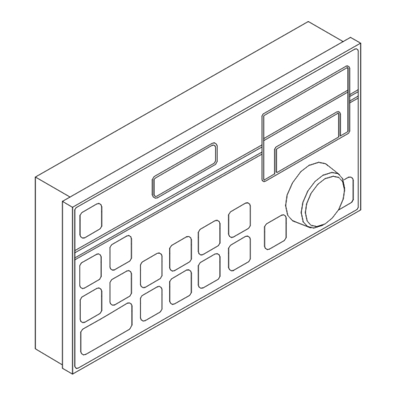
Robertson AP9 Adaptive Autopilot Fig. 1-1 Basic System 1.2.1 Control Unit All settings and operation of the autopilot take place on the control unit. In addition to push buttons it has three LCD- displays and a rotary course selector knob on the front panel. The control unit is made of seawater resistant aluminium and has a polyester coating to protect it against the environment. -
Page 11: Heading Sensors
Instruction manual 1.2.3 Heading Sensors Ref. to Fig. 1-2. The Control Unit is designed to accept several types of heading sensors (compasses). The sensors can be divided in three groups: • Gyrocompass • Magnetic Compass (Back-up compass) • Fluxgate Compass (Optional back-up compass) The terms main compass and monitor compass are used in this document. - Page 12 Robertson AP9 Adaptive Autopilot GYRO COMPASS: Gyrocompass with serial output is connected to the Main Computer. Gyrocompass with SYNCHRO (internal or external excitation) or STEP signal is connected to the Control Unit that must be equipped with the Gyro Interface Board. See table below.
-
Page 13: Rf14Xu Rudder Feedback Unit
Instruction manual MAGNETIC COMPASS For the autopilot to read the vessel's magnetic compass a CD109 Course Detector must be mounted on the compass. The signal from the Course Detector is connected to the Control Unit. 1.2.4 RF14XU Rudder Feedback Unit This unit transmits two electrical signals proportional to the rudder angle. -
Page 14: Options Available With The Standard System
Robertson AP9 Adaptive Autopilot rudder angle can be set without using a rudder angle indicator. Dimensions and design are the same as the S9, and it has a mid- position detent. 1.2.7 Options available with the standard system The autopilot system has several options allowing the system to be configured for various type of vessels. - Page 15 Instruction manual Where the system is to operate two sets of solenoid valves, one extra solid state PCB (S.S.B.) must be mounted in the D9X distribution Unit. Mode selector and speed input are mandatory for all Note ! installations. The mode selector is normally provided with the steering control system.
-
Page 16: Standard System, Analogue Output
Robertson AP9 Adaptive Autopilot 1.2.9 Standard System, Analogue output Except for the type of distribution unit the system is the same as the above. Analogue output is used when there is an existing steering control system on the vessel that will accept an analogue control signal from the autopilot. -
Page 17: Theory Of Operation
Instruction manual Theory of operation 1.3.1 Adaptive autopilot The adaptive autopilot is, within limits, able to identify the steering characteristics of a ship. This is done by comparing the output from a mathematical model and the vessel itself. The parameters calculated from this comparison are used to obtain optimal rudder commands in order to keep the vessel on a pre- set course. -
Page 18: Turning Procedures
Robertson AP9 Adaptive Autopilot 1.3.2 Turning procedures The automatic steering is oriented towards turn geometry, which is seen as a necessity within a modern ANTS (Automatic Navigation and Tracking System), where routes are planned on, and commanded by an ECDIS (Electronic Chart Display Information System). -
Page 19: Ants-Navigator Control
Instruction manual Turning The operator should think in terms of straight lines and circular arcs. A turn is specified by a course change (limited to 360º in each direction) and a turn radius. Optionally a rate of turn can replace the radius. The autopilot will automatically insert distinct wheel-over and counter-rudder phases as shown in Fig. - Page 20 Robertson AP9 Adaptive Autopilot controller aims at positioning the pivot point of the ship, which is the point that the ship rotates about during normal manoeuvring, on the line. Due to the varying quality of different position fixing systems, parameter TRACK RSP has been supplied, which balances the tracking precision and the rudder commands.
-
Page 21: Traditional Navigator Control
Instruction manual The off-track setpoint will be maintained during the turn. The turn radius originally set will be modified to make this possible. If the resulting radius reaches a set-able minimum, the off-track value experienced during the turn may vary somewhat from the setpoint. - Page 22 Robertson AP9 Adaptive Autopilot 1-14 20169140B...
-
Page 23: Autopilot Operation
Instruction manual AUTOPILOT OPERATION Quick reference This section is made as a quick reference to the most basic operations. These are all that are needed to use the autopilot as a standard course controller. Make sure however, that the autopilot has been properly installed prior to using the procedures. -
Page 24: Course Display
Robertson AP9 Adaptive Autopilot Whenever AUTO ON is pressed the autopilot will be brought back to this starting point. If the gyrocompass interface is not on a 1:1 ratio (step- Note ! signal, 90:1 or 360:1 synchro signal), the display will prompt you to adjust the compass reading before the main panel is shown. -
Page 25: Pre-Set Turn Procedure
Instruction manual Toggle between rate and radius submodes by pressing ROT/RAD. The current choice is shown on the lower line in the info display. Now set the rate or radius by operating the INCREASE and DECREASE buttons. Both the desired course and the rate or radius can be adjusted during the turn. -
Page 26: Back To Main Panel
Robertson AP9 Adaptive Autopilot 2.1.8 Back to MAIN panel To leave sub menus without causing any side effects, press CLEAR. This always brings you back to the top level, called the MAIN panel. 2.1.9 Muting and viewing alarms Alarms are muted and acknowledged by pressing CLEAR. As a reminder, the upper line of the text display will flash FAILURE or WARNING for as long as the failure exists. -
Page 27: Off-Track Command
Instruction manual The autopilot is connected to a traditional navigator. NAV mode NAVIGATOR MODE will not be engaged because of locking conditions or NOT ACCEPTED insufficient navigator data. The autopilot is connected to an ANTS-navigator. ANTS TRACK ANTS TRACK MODE mode will not be engaged because of locking conditions or NOT ACCEPTED insufficient navigator data. -
Page 28: Start Up Messages
Robertson AP9 Adaptive Autopilot 2.2.1 Start up messages When the autopilot is turned on, the display will show the following sequence of information before reaching the main panel (which is described below). Version identifier of control unit software. CU9 SW: ccccccc ccccccc INITIATING! CPU INITIATING... -
Page 29: Main Panel In Automatic Modes
Instruction manual 2.2.3 Main panel in automatic modes This is the main panel info display structure in all automatic -------------- modes. Explanation of text and symbols are as follows: eeee mmmmmmmmm mmmmmmmmmmm Current control mode. Text - AUTOPILOT Automatic steering mode. -
Page 30: Main Panel In Manual Modes
Robertson AP9 Adaptive Autopilot 2.2.4 Main panel in manual modes This is the main panel info display structure in all manual pppppppppppppppp modes. Explanation of text and symbols are as follows: eeee AUTOPILOT pppppppppppppppp Current mode Text - STANDBY External override. Text - MANUAL NFU Manual, non- follow-up tiller. -
Page 31: Preset Panels
Instruction manual DECREASE Decreases value in vvvvvv display. ROT/RADIUS Toggles between rate-of-turn and radius turn control. INFO Enables the INFO SELECT or INFO ALARM panel. ILLUM Enables ILLUMINATION ADJUST panel. AUTO ON Reenters the automatic steering mode. CLEAR Close the panel. OFF When depressed in 2-3 seconds, the autopilot will be turned off. -
Page 32: Off Track Preset Panel
Robertson AP9 Adaptive Autopilot CLEAR Close the panel. OFF When depressed in 2-3 seconds, the autopilot will be turned off. This panel is enabled either by pressing TURN PRESET, Note ! or automatically when a turn is due at the navigator. It is possible to leave the panel temporarily by pressing CLEAR. -
Page 33: Info Panels
Instruction manual The turn rate or radius used for the manoeuvre corresponds to • user parameters TURN MODE and TURN aaa. To stop a manoeuvre set off-track command to zero or restart • ANTS. 2.2.9 Info panels Pressing INFO from the MAIN panel when an active alarm or warning is displayed, will open the INFO ALARM panel. -
Page 34: Info Adjust Panel
Robertson AP9 Adaptive Autopilot Active keys INFO Goes through submenu headers. INCREASE Selects the indicated parameter submenu. AUTO ON Reenters the automatic steering mode. ILLUM Enables ILLUMINATION ADJUST panel. CLEAR Exits INFO SELECT panel. OFF When depressed in 2-3 seconds, the autopilot will be turned off. 2.2.12 Info adjust panel This is the INFO ADJUST panel info display structure. -
Page 35: Alarm Panel
Instruction manual 2.2.13 Alarm panel The alarm panel is invoked automatically upon failure and aaaaaaaaaaaaaaaa warning conditions. aaaaaaaaaaaaaaaa Active keys CLEAR Acknowledge alarm and return to MAIN panel. OFF When depressed for a while, the autopilot will be turned off. Notes •... -
Page 36: Compass Select Panel
Robertson AP9 Adaptive Autopilot 2.2.15 Compass select panel This is the COMPASS SELECT panel info display structure. mmmmmmmmmmmmmmmm Explanation of text and symbols are as follows: cccccccccccccccc mmmmmmmmmmmmmmmm Compass usage Text MAIN COMPASS Main compass can be selected. Text MONITOR COMPASS Monitor compass can be selected. cccccccccccccccc Shows the compass currently selected. -
Page 37: Setting Up The Autopilot
Instruction manual Setting up the Autopilot This section contains an overview off all adjustable parameters of the Autopilot, and procedural descriptions of how to access and adjust the parameters. The parameters are divided in five different groups with different levels of access, depending of need for use. The groups are as follows: 1. -
Page 38: User Setup
Robertson AP9 Adaptive Autopilot To adjust a parameter; make sure the correct parameter has been accessed, and then change it by means of the INCREASE or DECREASE button. Note ! • When accessing the dockside parameters you will be asked to present a password;... - Page 39 Instruction manual Turn rate or radius to use for immediate turns, deg/min or SEATRIAL SETUP: nautical miles. TURN aaa vvvvvv Precision Rudder activity factor. This parameter tells the SEATRIAL SETUP: autopilot how much rudder it should use to stay on course. RUDD GAIN x.x°/º...
-
Page 40: Dockside Setup
Robertson AP9 Adaptive Autopilot 2.3.5 Dockside setup These parameters are to be set during installation, and adjusted if required to match new installed equipment. Displays commanded rudder and actual rudder angle. DOCKSIDE SETUP: – = port. RUDD ccc Used for rudder feedback alignment (Ref. section 4.5, last page). -
Page 41: Service Setup
Instruction manual Software option code. To be zero unless specified otherwise in MASTER SETUP: appendices. OPTIONS To make a master reset, press the OFF button while at the same PRESS PASSWORD time pressing INCREASE. Hold both down until all displays TO MASTER RESET are blank. -
Page 42: Dockside Preparations
Robertson AP9 Adaptive Autopilot Dockside preparations This sections describes the procedures to follow when starting up the autopilot for the first time and how to ensure that everything is ready for sea trial. 2.4.1 First startup Make sure that the mode selector is in position “manual”, to disengage the autopilot. -
Page 43: Autopilot Test Setup
Instruction manual and adjusting parameters, paragraph 2.3.2. Adjust if needed. Give reasonable values to the seatrial setup parameters: TURN aaa. These ACC LENGTH, TURN MODE parameters are important for the vessel’s performance during turns. It is recommended to read about in Theory of operation page 1-10. -
Page 44: Sea Trial Procedure
Robertson AP9 Adaptive Autopilot Sea trial procedure This section describes the procedures to follow when the autopilot is in use for the first time or after a master reset. The activity is here called the sea trial. The purpose is to let the autopilot learn the ships manoeuvring characteristics. -
Page 45: Navigator Control
Instruction manual system performance, section 2.6.6. Due to the need for exposure to different disturbance patterns, the parameters may have to be readjusted after gaining experience with the autopilot. 3. Return to the main panel by pressing CLEAR. If the lower line of the info display shows “PREC AUTOPILOT”, switch to the economy submode by pressing PREC / ECON. -
Page 46: Save Settings
Robertson AP9 Adaptive Autopilot 2.5.3 Save settings After the sea trial procedure, it is important to save the settings for later use. This is done by turning off the autopilot as described in the Quick reference, section 2.1. In order to restore these settings later, in case of a malfunction, it is necessary to make a backup copy of current settings. - Page 47 Instruction manual Date User setup Range (Step size) Defaults Before sea trials After sea trials RUDD LIMIT 13º 5 - 40 (1) Depends on difference between main and monitor compasses COMP DIFF WAVE FILT ON, OFF OFF-CRS L 10º 3 - 55 (1) COMPDIFF L 10º...
-
Page 48: User Troubleshooting
Robertson AP9 Adaptive Autopilot User Troubleshooting 2.6.1 Basic troubleshooting Displays are blank and nothing works. This occurs when the system has been shut down. It might also be due to power failure or a non-complete installation. Make sure that the installation is complete.. Press the button to turn on the system. -
Page 49: Failure Messages
Instruction manual The control panel is waiting for contact with the main computer. This message appears whenever the system is CPU INITIATING powered up. PLEASE WAIT Wait for approx. 60 seconds for the message to disappear and the system to be ready. If the message remains, check if the Main Computer is turned on and powered up. - Page 50 Robertson AP9 Adaptive Autopilot Invalid data detected by the navigator. This usually reflects a FAILURE: temporary problem with your navigators position fixing system. The INVALID NAV DATA system automatically switches to automatic steering. Check the navigator for a probable cause. Wrong sentence structure from navigator.
-
Page 51: Warning Messages
Instruction manual Malfunction of D93 • Check that the ±10V is present at the input terminals TB4-3/4 (Interconnection PCB) • Disconnect the analogue signal from the dual analogue PCB (TB20, 1-2 and TB21, 1-2. If ±10V is normal, the analogue PCB must be replaced. Main compass failure. -
Page 52: Control System Performance
Robertson AP9 Adaptive Autopilot A more serious cause to the warning is the failure of one of the two compasses. Check the operation of both compasses. Rudder limit reached. This may be caused by wave dis- WARNING: RUDDER LIMIT turbance or improper parameter settings. It may also indicate a failure in the control system. -
Page 53: Course Keeper
Instruction manual 1. Compass accuracy and lag. 2. Speed log accuracy and reliability. 3. Rudder feedback accuracy (alignment and linkage) and possible interference. 4. Speed and backlash of rudder. 2.6.7 Course keeper Consider tuning seatrial setup parameters RUDD GAIN, ECON RUDD, MIN RUDD and DEADBAND, and whether the wave filter (user parameter WAVE FILT) should be enabled or disabled. -
Page 54: Navigator Control
Robertson AP9 Adaptive Autopilot essence and assuming that the turn rate or radius is reasonable... much rudder counter rudder results from ACC LENGTH being too small. Too little rudder and counter rudder is the result of a too large ACC LENGTH value. 2.6.9 Navigator control Parameter TRACK RSP determines the correctional effort made by the cross-track controller. -
Page 55: Technical Specifications
Instruction manual TECHNICAL SPECIFICATIONS Control Unit Dimensions:........See Fig. 3-1 Weight: ..........3.0 kg Protection:..........IP43* Ambient temperature, storage:..-25 - +70°C operation: 0 - +55°C Safe distance to magnetic comp.: ...0.3m Maximum current consumption : ..0.6A Input signals: Magnetic compass: ......sin/cos ±2V, 2.5V ref. (exitation by autopilot) Fluxgate compass: ......sin/cos ±2V, 2.5V ref. -
Page 56: Ap9Mkii Gyro Interface Pcb
Robertson AP9 Adaptive Autopilot Fig. 3-1 AP9 Adaptive Control Unit - dimensions AP9MKII Gyro Interface PCB Input signals: Synchro 1:1 (signal levels: See previous page) Synchro 90:1 (signal levels: See previous page) Synchro 360:1 (signal levels: See previous page) Autopilot exitated synchro 1:1 Step voltage 6 step/deg, 24-70V 20169140B... -
Page 57: Cd109 Course Detector
Instruction manual CD109 Course Detector Dimensions:...........See Fig. 3-2 Weight: ...........0.3 kg Protection:..........IP56 Ambient temperature, storage:..-40 - +85°C operation: ..-30 - +60°C Cable length:..........1 m 1000 (39.4") 120° 120° 120° 35 (1.4") m in/m ax. 80-100 (3.2-4.3") Fig. -
Page 58: Main Computer
Robertson AP9 Adaptive Autopilot Main Computer 3.4.1 MC100 Main Computer Dimensions:..........See Fig. 3-3. Weight: ............13.0 kg Protection: ..........IP22 Ambient temperature, storage:....-25 - +70°C operation:.... 0 - +55°C Safe distance to magnetic compass: ..1.5 m (5') Main input voltage: ...... -
Page 59: Mc9 Main Computer
Instruction manual 3.4.2 MC9 Main Computer (Previous model) Dimensions:........See Fig. 3-3. Weight: ..........11.5 kg Otherwise as for MC100 Fig. 3-4 MC9 Main Computer - Dimensions Drw. no. N3-016885 20169140B... -
Page 60: Distribution Unit
Robertson AP9 Adaptive Autopilot Distribution Unit Dimensions:........See Fig. 3-5. Weight: ..........3.5 kg Protection: .........IP22 Ambient temperature, storage:..-25 - +70°C operation: 0 - +55°C Safe distance to magnetic compass: 1.5 m (5') Main input voltage: ......24V DC +30/-25 % Alarm voltage : .........24V DC ±20 % Input signals: Rudder Feedback Unit:....3400Hz ±20Hz/degree Steering Lever... - Page 61 Instruction manual Fig. 3-5 D9X Distribution Unit - Dimensions 20169140B...
-
Page 62: Rf14Xu Rudder Feedback Unit
Robertson AP9 Adaptive Autopilot RF14XU Rudder Feedback Unit Dimensions:......See Fig. 3-6. Weight: ........2.8 kg Protection:....... IP56 Ambient temperature:... -10 - +55°C Operating voltage:....24V DC +30/–20% (Frequency section 12-40V DC) Voltage output: Rudder indicator: 0-18V DC (9V as midship reference) Frequency output: Autopilot feedback: 3400Hz (midship reference). -
Page 63: Rf Standard Transmission Link
Instruction manual RF Standard Transmission Link Fig. 3-7 RF Standard Transmission Link – dimensions 20169140B... - Page 64 Robertson AP9 Adaptive Autopilot 3-10 20169140B...
-
Page 65: Installation
Instruction manual INSTALLATION General Common sense and experience should be used when installing the units, particular attention being given to the operator's need for ease of access. To avoid Radio Frequency Interference the use of Shielded cables and proper termination of the shield(s) must be observed. - Page 66 Robertson AP9 Adaptive Autopilot Fig. 4-2 Control unit - bracket mounting Connector assemble The cable conductors are connected to the connector block according to the connection lists drw. no. N4-016896. The following tools are required to crimp the connector pins and sockets to the individual cable conductors: Crimping tool : Amp 58495-1 Extraction tool: Amp 725840...
- Page 67 Instruction manual shell onto the connector block. Fix the cable screen to the shell by a wire strap and tighten well to make sure the screen has good contact. Apply a thin layer of copa slip on the shell threads. Screw the cover onto the shell until it makes good connection with the control unit cabinet.
-
Page 68: Heading Sensors
Robertson AP9 Adaptive Autopilot Heading sensors 4.3.1 General The heading sensor must be connected to the main Control Note ! Unit (or Main Computer). The autopilot is capable of reading most types of heading reference sensors. These can be gyro compasses, magnetic compasses and fluxgate compasses. - Page 69 Instruction manual be factory mounted (the control unit serial number has an “F” identifier). Further more, the Control Unit must be set up for the correct type of gyro, correct phase- and reference voltage and whether gyro signal is autopilot excitated or not. This is done by means of DIP switches (two packages with 8 switches in each), mounted on the back side of the Interface Board.
- Page 70 Robertson AP9 Adaptive Autopilot Make sure that the internal dip switches, SW1-2 are correctly set according to the list below. The setting of SW2 only applies for synchro input. Gyro type selection Stepper (6 steps/degree) 24, 35, Synchro 1:1, autopilot ref. volt. Synchro 1:1, gyro ref.
-
Page 71: Magnetic Compass
Instruction manual Make sure that switches SW1 and SW2 are correctly set Note ! before connecting the plug. Gyro compass with serial output is connected to the Main Computer. 4.3.3 Magnetic compass Before mounting the CD109 Course Detector make sure the compass is compensated and located at a place free from vibration and disturbing magnetic interference such as the engines, cables, transmitter antennas or other electro magnetic... - Page 72 Robertson AP9 Adaptive Autopilot There is no patent cure for this problem, besides making a proper installation and compensation of the compass. CD109 Course Detector mounting Fig. 4-5 CD109 Course detector - Mounting The course detector is mounted on the ship's magnetic compass to transmit a heading signal to the control unit.
- Page 73 Instruction manual The compass should be checked for free movement in the gimbals without stressing the detector cable. The CD109 Course Detector is connected to J2 on the Control Unit, and the connection is shown on connection list drw. no. N4-016896/1.
-
Page 74: Rgc Signal Interface Unit
Robertson AP9 Adaptive Autopilot 4.3.4 RGC Signal Interface Unit (Part of Robertson RGC Gyro compass delivery) The RGC Signal Interface Unit is designed to generate heading signals of different formats when connected to either RGC50, RGC10 or RGC11. The heading signal used by AP9 Adaptive is the sine/cosine output, and the interconnection is shown in Fig. -
Page 75: D90/D91/D92/D93 Distribution Unit
Instruction manual D90/D91/D92/D93 Distribution Unit General Depending on type of Distribution Unit, the solid state relays are capable of operating solenoids for high and low DC or AC. Analogue voltage or current signal is also available for steering gears control systems that require analogue input signals. The relation between type of Distribution Unit and control voltage is as follows: D90: Single relay output for low DC (19-40V) - Page 76 Robertson AP9 Adaptive Autopilot the board must be set up during installation in accordance with the set up procedure below. Analogue rudder signal (±10V) When using the analogue signal, normally 0±10V, the rudder response is checked both for correct direction and deflection. First make sure that the output from the Dual Analogue PCB matches the required input signal for the rudder amplifier.
- Page 77 Instruction manual Dual Analogue PCB up to Rev. C SW1/SW11 Signal GAIN OFFSET Remarks 0±10V RV5/RV15 RV3/RV1 Required span set SW1/SW11 Span adj. 3 (±3V) by RV5/RV15 (4- 10V). Offset set by RV3/RV13. X ±Y (volt) RV5/RV15 RV4/RV1 Adjust "X" (i.e. SW1/SW11 i.e.: 12 ±6V "Y"...
- Page 78 Robertson AP9 Adaptive Autopilot S1, S2, S11, S12 Selection of input signal from bus or from external input TB21 S21, S22 RV1, RV11 Pos. 0: (Channel 1 and 2) Rudder feedback 40mA output signal to autopilot adjust Pos. 1: 10kHz signal to autopilot (not used) RV2, RV12 (Channel 1 and...
- Page 79 Instruction manual S21, S22 Pos. 0: Rudder feedback signal to autopilot Pos. 1: 10kHz signal to autopilot RV3, RV13 (Channel 1 and 2) Input offset adjust S1, S2, S11, S12 RV5, RV15 Selection of (Channel 1 and 2) input signal Gain reduction on from bus or input signal...
- Page 80 Robertson AP9 Adaptive Autopilot No strap connections: Safe relay controlled by autopilot Connection between S1 and S2: Safe relay controlled by NFU-handle and autopilot Connection between S2 and S3: Safe relay ON Power ON Current limiter ON Starboard command Safe relay Port command Current...
-
Page 81: Rf14Xu Rudder Feedback Unit
Instruction manual RF14XU Rudder Feedback Unit Mechanical mounting Before installation check that the alignment mark on the mounting plate agrees with the mark on the shaft. Bring the rudder to amidships position. The feedback unit should be mounted on a plane surface and secured by bolts through the three holes in the mounting plate. - Page 82 Robertson AP9 Adaptive Autopilot must be connected to the internal ground terminal. Ref. Fig. 4-12. The feedback unit has an external ground terminal an must have a proper ground connection to the hull. The grounding wire should be as short as possible and at least 10 mm wide. The RF14XU is divided into two sections.
- Page 83 Instruction manual of the RF14XU terminal board must be connected to terminal 9. See Fig. 4-13. VIOLET R F14X U EL EC TR ONIC MOD ULE B R O W N (VIE WED FROM BACK S IDE) P I N K N OT E 2 BLUE (GND) YELLOW (+ 5V)
- Page 84 Robertson AP9 Adaptive Autopilot Final check After installation, the cable glands must be sealed with silicon to prevent water from seeping in. Also apply silicon grease to the gasket between the bottom and top cover. On the inside of the feedback unit cover, a piece of moisture protecting sponge is attached.
-
Page 85: Mc100 Main Computer
Instruction manual MC100 Main Computer The Main Computer must be mounted horizontally on the shock absorber frame. It is fastened by 8 screws through 8 mm holes (Fig. 3-3). Internal cables All internal signal connections between the units are made by cables with plugs in both ends. - Page 86 Robertson AP9 Adaptive Autopilot Pull out each terminal before connecting the wires. Remove all stands before remounting the Main Computer. Channel 1 Channel 8 Fig. 4-15 Main Computer Interface Board, Component layout The Main Computer Interface board has terminal connections for Mains, speed log (pulse) and 8 identical communication channels.
- Page 87 Instruction manual 8 (TB19): Optional Debug data Each channel has a jumper switch for selection between different input signal formats: Position Norm: RS-232 and NMEA 0183 format Position Cl: 5-20mA current loop Position “CL” must be used on channel Note ! 1-3 to the control unit(s).
- Page 88 Robertson AP9 Adaptive Autopilot ALARM SYSTEM and KEYBOARD CONTROLLER are normally not used. Fuses Test port Log input (pulse) Fig. 4-17 Main Computer Interface Board, component layout - left part 4-24 20169140B...
-
Page 89: Mode Selection
Instruction manual Mode Selection Mode selection is normally incorporated in a centralized change-over system and is connected to the D9X Distribution Unit as fixed level signals according to Fig. 4-18. Fig. 4-18 Mode selector 4.7.1 Mode selection options It is possible to have a “push to take command” arrangement for mode selection with pulsed level mode signals. - Page 90 Robertson AP9 Adaptive Autopilot 4-26 20169140B...
-
Page 91: Maintenance
Instruction manual MAINTENANCE Upgrading the autopilot software It is possible to upgrade the software of the Main Computer. The procedure depends on whether it is an MC9 or an MC100 model. You will receive the new software version on an upgrade diskette. -
Page 92: Mc9 Main Computer
Robertson AP9 Adaptive Autopilot 5.1.2 MC9 Main Computer 1. Press the OFF button on the main control unit to turn off the system. 1. Remove the top cover disable watchdog by connect- ing J7-2 with J3-2 on MC9 Power Distribu- tion Board. -
Page 93: Cleaning
Instruction manual parameters as a backup diskette. Whenever it is used afterwards, it restores the configuration of the parameters which are saved on the diskette. Use the following procedure to make a backup or to restore it: 1. Insert the backup/restore diskette into the Main Computer diskette station. - Page 94 Robertson AP9 Adaptive Autopilot 20169140B...
-
Page 95: Spare Parts
Instruction manual SPARE PARTS Control Unit 20168837 AP9 Adaptive Control Unit with accessories 20168860 AP2000 Track Pilot Control Unit with accessories 20168936 AP9 Adaptive Control Unit 20168902 AP2000 Track Pilot Control Unit 20120994 Accessories 20169330 EMC kit type 9 20168928 AP9 Adaptive front housing ass’y 20168894 AP2000 Track Pilot front housing ass’y... -
Page 96: Mc100 Main Computer
Robertson AP9 Adaptive Autopilot 44155232 Solid state relay 24V DC (D90) 44155265 Solid state relay 110V DC (D91) 44155240 Solid state relay 220V AC (D92) 44154417 Fuse 2.5A 5x20mm quick 44103679 Fuse 5A 5x20mm quick 20126678 D9X Dual Analogue Board 20123253 D9X/S Relay Assy MC100 Main Computer... -
Page 97: Cd109 Course Detector
Instruction manual 26044800 MC9 Interface Unit 26044826 Interface signal cable 26044834 Interface power cable 26044784 MC9 Interface PCB ass’y 20169454 MC9 Back-up diskette 20169280 MC9 System diskette CD109 Course Detector 20120861 CD109 Course Detector with holder 20120721 CD109 Course Detector 20331997 Holder for Course Detector 44112126... -
Page 98: Rf14Xu Rudder Feedback Unit
Robertson AP9 Adaptive Autopilot RF14XU Rudder Feedback Unit 22501647 RF14XU Rudder Feedback Unit w/transmission link 22501654 RF14XU Rudder Feedback Unit 22504005 Transmission Link 44132306 Ball joint 22500300 Shaft coupling 22500458 Gasket 22501605 Electronic XU drive module 44105120 Actuator 44105146 Limit switch 44118388 Potentiometer 5 Kohm 44132033... -
Page 99: Rf Standard Transmission Link
Instruction manual RF Standard Transmission link 22504005 Transmission link complete 44132306 1 Ball joint, 8 mm stainless 44132322 2 Transmission rod M8x300 mm 44150225 3 Lock nut M8 (Hex) 22504021 4 Transmission lever Ø12 mm 44152676 5 Socket set screw M6x10 44151967 6 Washer M8 22504054... - Page 100 Robertson AP9 Adaptive Autopilot 20169140B...
-
Page 101: Drawings
Instruction manual DRAWINGS Cabling diagram (D90-D92 Distribution Unit) ..N3-016898 (page 1) Cabling diagram (D93 Distribution Unit)....N3-016898 (page 2) Cable specification list ..........N4-016897 Connection list ............N4-016896 (page 1-7) D9X Power Supply ........... N3-012812 D9X Interconnection Board........N2-012813 D9X Solid State Board . - Page 102 Robertson AP9 Adaptive Autopilot Cabling diagram (D90-D92 Distribution Unit) N3-016898A (page 1) 20169140B...
- Page 103 Instruction manual Cabling diagram (D93 Distribution Unit) N3-016898A (page 2) 20169140B...
- Page 104 Robertson AP9 Adaptive Autopilot Cable specification list N4-016897 20169140B...
- Page 105 Instruction manual Connection list N4-016896B (page 1 of 7) 20169140B...
- Page 106 Robertson AP9 Adaptive Autopilot Connection list N4-016896A (page 2 of 7) 20169140B...
- Page 107 Instruction manual Connection list N4-016896B (page 3 of 7) 20169140B...
- Page 108 Robertson AP9 Adaptive Autopilot Connection list N4-016896 (page 4 of 7) 20169140B...
- Page 109 Instruction manual Connection list N4-016896 (page 5 of 7) 20169140B...
- Page 110 Robertson AP9 Adaptive Autopilot Connection list N4-016896A (page 6 of 7) 7-10 20169140B...
- Page 111 Instruction manual Connection list N4-016896A (page 7 of 7) 7-11 20169140B...
- Page 112 Robertson AP9 Adaptive Autopilot 7-12 20169140B...
-
Page 123: Appendix A: D93 With Four Analogue Output Signals
Instruction Manual APPENDIX A D93 with four ±10V analogue output signals This function is achieved by using two Dual Analogue PCB's, each providing two galvanic isolated ±10V signals. In order to provide four "change-over" signals for the propulsion equipment, an extra relay module has been mounted in the D93 unit. - Page 124 Robertson AP9 Adaptive Autopilot The interconnection between the control unit and the D93 unit is shown on drw. no. N4-017086, and the connection between each propulsion unit and the D93 is shown on Fig. Appendix A D93/2-SR4 TB21 Dual Analog PCB 1 TB22 Relays...
-
Page 125: Appendix B: Extended Use Of Mode Selection
Instruction Manual APPENDIX B Extended use of mode selection Description Each control unit has the following lines for mode selection: • Mode 1 (J1-1) • Mode 2 (J1-2) • Common (J1-13) For the main control unit these lines are normally run to the D9X Distribution Unit where the external mode control is connected. - Page 126 Robertson AP9 Adaptive Autopilot automatic mode (started by push on AUTO-button) a pulse on the Mode 1 line will bring the autopilot back to manual mode. The following table and state diagram show this. Pulsed level table: Initial Mode 1 Mode 2 Action Display text...
- Page 127 Instruction Manual NFU - AUTO FU - AUTO D9X INTERCONNECTION PCB D9X INTERCONNECTION PCB Link MODE 1 MODE 1 MODE 2 MODE 2 Link AUTO AUTO COMMON COMMON MODE SELECTOR MODE SELECTOR STANDBY - NFU - FU - AUTO AUTO COMMON MODE 1 MODE 2...
- Page 128 Robertson AP9 Adaptive Autopilot Set the software option code according to option in use. MASTER SETUP: Fixed: 0 OPTIONS Pulsed: 1 20169140B...
-
Page 129: Appendix C: Ux Converter Unit
Instruction manual APPENDIX C UX Converter Unit In some occations it is required to use a separate potentiomenter for sensing the rudder movement. When so, it is also necessary to convert the potentiometer voltage signal to a frequency signal, identical to the signal from our RF14XU. A separate box containing the electronic XU module and two trimpotentiometers has therefore been made. - Page 130 Robertson AP9 Adaptive Autopilot UX Converter Unit – Connections For selection of rudder deflection, refer to Fig. 4-13. 20169140B...
Need help?
Do you have a question about the SIMRAD Robertson AP9 and is the answer not in the manual?
Questions and answers