Table of Contents
Advertisement
Quick Links
Installation, Operation,
and Maintenance
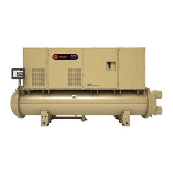
HDWA Water-cooled Agility™ ™ Chillers
With Tracer® AdaptiView™ Control
Model: HDWA
PC 747
Only qualified personnel should install and service the equipment. The installation, starting up, and servicing of heating, ventilating, and
air-conditioning equipment can be hazardous and requires specific knowledge and training. Improperly installed, adjusted or altered
equipment by an unqualified person could result in death or serious injury. When working on the equipment, observe all precautions in the
literature and on the tags, stickers, and labels that are attached to the equipment.
October 2019
S S A A F F E E T T Y Y W W A A R R N N I I N N G G
H H D D W W A A - - S S V V X X 0 0 0 0 1 1 D D - - E E N N
X39641347004
Advertisement
Table of Contents

Related Manuals for Trane Agility HDWA


Summary of Contents for Trane Agility HDWA
- Page 1 Installation, Operation, and Maintenance HDWA Water-cooled Agility™ ™ Chillers With Tracer® AdaptiView™ Control Model: HDWA PC 747 X39641347004 S S A A F F E E T T Y Y W W A A R R N N I I N N G G Only qualified personnel should install and service the equipment.
- Page 2 A A L L W W A A Y Y S S r r e e f f e e r r t t o o a a p p p p r r o o p p r r i i a a t t e e M M a a t t e e r r i i a a l l S S a a f f e e t t y y impact to the environment. Trane advocates the...
- Page 3 , , t t h h o o s s e e r r e e g g u u l l a a t t i i o o n n s s s s u u p p e e r r s s e e d d e e • Start-up must be performed by Trane or an agent of t t h h e e s s e e p p o o l l i i c c i i e e s s . .
-
Page 4: Table Of Contents
Table of Contents Unit Nameplate......6 Freeze Protection ......23 Compressor Nameplate . - Page 5 Appendix B: Agility™ Chiller Installation Run Inhibit ......55 Completion and Request for Trane Immediate Shutdown to Stopped or Service .
-
Page 6: Unit Nameplate
Unit Nameplate The unit nameplate is located on the right side of the Figure 1. Typical unit nameplate control panel. A typical unit nameplate is illustrated in the following figure and contains the following information: • Unit model and size descriptor •... -
Page 7: Compressor Nameplate
U U n n i i t t N N a a m m e e p p l l a a t t e e Compressor Nameplate Figure 2. Compressor nameplate The compressor assembly has a separate model number which is required to identify internal and external compressor parts. -
Page 8: Model Number Descriptions
Model Number Descriptions Digit 1, 2 — Unit Function Digit 16 — Evaporator Tube Bundle Digit 25 — Control: Generic Building Automation System (BAS) HD = Agility™ Centrifugal Water-cooled A = Evaporator Tube Bundle A 0 = None Chiller B = Evaporator Tube Bundle B G = Generic BAS C = Evaporator Tube Bundle C Digit 3 —... - Page 9 M M o o d d e e l l N N u u m m b b e e r r D D e e s s c c r r i i p p t t i i o o n n s s HDMA Centrifugal Compressor AFDT Adaptive Frequency Drive Digit 13 —...
-
Page 10: General Information
General Information Unit Description chillers and their components. Water inlet and outlet openings are covered before shipment. The unit ships Agility™ chillers are centrifugal, water-cooled liquid charged with refrigerant. chillers designed for indoor installation. Each unit is a completely assembled, hermetic package that is Component Locations factory-piped, wired, leak-tested, dehydrated, charged, and tested for proper control operation before... - Page 11 G G e e n n e e r r a a l l I I n n f f o o r r m m a a t t i i o o n n Figure 4. Typical Agility chiller component location (back view) HDWA-SVX001D-EN...
-
Page 12: Adaptive Frequency Drive
G G e e n n e e r r a a l l I I n n f f o o r r m m a a t t i i o o n n Adaptive Frequency Drive Figure 6. Assembly harmonic filter options Figure 5. -
Page 13: Unit Clearances
G G e e n n e e r r a a l l I I n n f f o o r r m m a a t t i i o o n n Unit Clearances Figure 7. Clearance requirements, in. (cm) HDWA-SVX001D-EN... -
Page 14: Dimensions And Weights
G G e e n n e e r r a a l l I I n n f f o o r r m m a a t t i i o o n n Dimensions and Weights Table 1. Agility chiller weights (lb) Shipping Weight Dimensions Operat-... -
Page 15: Unit Specifications-International
G G e e n n e e r r a a l l I I n n f f o o r r m m a a t t i i o o n n Unit Specifications—International Center of Gravity (mm) System (SI) Units Table 4. -
Page 16: Pre-Installation
F F a a i i l l u u r r e e t t o o f f o o l l l l o o w w i i n n s s t t r r u u c c t t i i o o n n s s b b e e l l o o w w c c o o u u l l d d r r e e s s u u l l t t i i n n ☐ Notify the Trane sales representative and arrange d d e e a a t t h h o o r r s s e e r r i i o o u u s s i i n n j j u u r r y y o o r r e e q q u u i i p p m m e e n n t t d d a a m m a a g g e e . - Page 17 Start-up must be performed by Trane or an agent of Trane specifically authorized to perform start-up and warranty of Trane® products. Contractor shall provide Trane (or an agent of Trane specifically authorized to perform start-up) with notice of the scheduled start-up at least two weeks prior to the scheduled start-up.
-
Page 18: Installation: Mechanical
(non-condensing I I m m p p o o r r t t a a n n t t : : Trane will not assume responsibility for conditions). If your equipment room/ equipment problems resulting from an... -
Page 19: Adaptive Frequency Drive Enclosure
I I n n s s t t a a l l l l a a t t i i o o n n : : M M e e c c h h a a n n i i c c a a l l N N O O T T I I C C E E Table 5. -
Page 20: Standard Chiller Lift
(end-to-end), the unit may require removal of the 2. Attach the lifting chains or cables. compressor. Contact Trane or an agent of Trane 3. After the lifting cables are in place, attach a safety specifically authorized to perform start-up and chain or cable between the first-stage of the warranty of Trane®... -
Page 21: Leveling The Unit
I I n n s s t t a a l l l l a a t t i i o o n n : : M M e e c c h h a a n n i i c c a a l l be cut to suit the application, but should cover the both the condenser and evaporator;... - Page 22 I I n n s s t t a a l l l l a a t t i i o o n n : : M M e e c c h h a a n n i i c c a a l l Figure 12.
-
Page 23: Freeze Protection
I I n n s s t t a a l l l l a a t t i i o o n n : : M M e e c c h h a a n n i i c c a a l l Freeze Protection freezing. - Page 24 I I n n s s t t a a l l l l a a t t i i o o n n : : M M e e c c h h a a n n i i c c a a l l Table 8.
-
Page 25: Installation: Water Piping
. . I I m m p p o o r r t t a a n n t t : : Trane strongly recommends using the... -
Page 26: Strainers
I I n n s s t t a a l l l l a a t t i i o o n n : : W W a a t t e e r r P P i i p p i i n n g g Strainers Figure 13. - Page 27 ® control module has no effect in Trane application. It is NOT necessary to O O v v e e r r t t i i g g h h t t e e n n i i n n g g ! ! make adjustments to the “Temp”...
-
Page 28: Evaporator And Condenser Water
I I n n s s t t a a l l l l a a t t i i o o n n : : W W a a t t e e r r P P i i p p i i n n g g N N O O T T I I C C E E Figure 16. -
Page 29: Water Piping Connections
Expenses that result from a failure to requirements (i.e., drainage, etc.). follow this recommendation will NOT be paid by Trane. N N o o t t e e : : If needed, plug-type sensor extension cables are Water piping connection sizes and components are available for purchase from Trane Parts Service. -
Page 30: Reversing Waterboxes
Flange Adaptor Style 77 Flexible Complete the waterbox switch and replace sensors. Trane provided Customer provided N N o o t t e e s s : : N N o o t t e e s s : : •... -
Page 31: Victaulic Gasket Installation
I I n n s s t t a a l l l l a a t t i i o o n n : : W W a a t t e e r r P P i i p p i i n n g g The flange-adapter gasket must be placed with the 4. -
Page 32: Pressure Testing Waterside Piping
Eddy Current Testing current technology and heat exchanger tubing. Trane recommends conducting an eddy current inspection of the condenser and evaporator tubes in HDWA-SVX001D-EN... -
Page 33: Insulation
Trane for further review. condensation . Chillers in high humidity areas or ice N N o o t t e e : : If the unit is not factory-insulated, install storage, low leaving water temperature (less than 36°F... - Page 34 I I n n s s u u l l a a t t i i o o n n Figure 22. Recommended area for unit insulation N N o o t t e e s s : : • Bulbwells, drain, and vent connections must be accessible after insulating.
-
Page 35: Electrical Requirements
Electrical Requirements Installation Requirements enclosure. If the AFD enclosure must be cut to provide electrical access, exercise care to prevent debris from W W A A R R N N I I N N G G falling inside the enclosure. Refer to submittal drawings. -
Page 36: Adaptive Frequency Drive
E E l l e e c c t t r r i i c c a a l l R R e e q q u u i i r r e e m m e e n n t t s s Adaptive Frequency Drive W W A A R R N N I I N N G G L L i i v v e e E E l l e e c c t t r r i i c c a a l l C C o o m m p p o o n n e e n n t t s s ! ! -
Page 37: System Control Circuit Wiring
EXPECTED TO BE 38°F OR LESS AND THAT THE METHOD USED IS INDEPENDENT OF THE PRIMARY WATER PROOF OF FLOW DEVICE TO PROVIDE REDUNDANCY. 7. IF OPTIONAL TRANE INSTALLED 1K22 AND/OR 1K23 WATER FLOW DETECTION CONTROLLERS ARE USED AND THE CUSTOMER CHOOSES TO INSTALL 5S17 AND/OR 5S18 SECONDARY PROOF OF FLOW DEVICES THEN THE CUSTOMER MUST REMOVE TRANE FACTORY WIRE BETWEEN 1X1-2 AND 1K23-4 AND/OR WIRE BETWEEN 1X1-3 AND 1K22-4. -
Page 38: Sensor Circuits
E E l l e e c c t t r r i i c c a a l l R R e e q q u u i i r r e e m m e e n n t t s s Table 13. - Page 39 E E l l e e c c t t r r i i c c a a l l R R e e q q u u i i r r e e m m e e n n t t s s Figure 24.
-
Page 40: Schematic Wiring Drawings
Please refer to the submittals and drawings that shipped with the unit. Additional wiring drawings for UC800 provides an optional LonTalk® Communication Agility™ chillers are available from your local Trane Interface (LCI-C) between the chiller and a Building office. Automation System (BAS). An LCI-C LLID shall be used to provide “gateway”... -
Page 41: Installation: Controls
Installation: Controls This section covers information pertaining to the UC800 controller hardware. For information about the Tracer® AdaptiView™ display, which is used to interface with the internal chiller data and functions provided by the UC800, refer to Tracer AdaptiView Display for Water-cooled Agility Chillers Operations Guide (HDWA-SVU001*-EN). -
Page 42: Communication Interfaces
I I n n s s t t a a l l l l a a t t i i o o n n : : C C o o n n t t r r o o l l s s Figure 25. - Page 43 I I n n s s t t a a l l l l a a t t i i o o n n : : C C o o n n t t r r o o l l s s Figure 26.
- Page 44 I I n n s s t t a a l l l l a a t t i i o o n n : : C C o o n n t t r r o o l l s s Figure 27.
-
Page 45: Installing The Tracer Adaptiview
8. Attach the Tracer® AdaptiView™ display to the I I m m p p o o r r t t a a n n t t : : For best results, Trane, or an agent of display support arm base plate (labeled E in the Trane, must install the Tracer ®... -
Page 46: Arm
I I n n s s t t a a l l l l a a t t i i o o n n : : C C o o n n t t r r o o l l s s Figure 30. -
Page 47: Operating Principles
BPHE results in further subcooling of the primary liquid mechanical problems do occur, however, contact a as it rejects heat to, and consequently superheats, the Trane service technician to ensure proper diagnosis secondary flow. The additional subcooling of the liquid and repair of the unit. -
Page 48: Uninterruptible Power Supply
O O p p e e r r a a t t i i n n g g P P r r i i n n c c i i p p l l e e s s Uninterruptible Power Supply ASME Code for refrigerant-side/working-side pressure of 200 psig (1379.0 kPaG). -
Page 49: Start-Up And Shut-Down
I I m m p p o o r r t t a a n n t t : : Initial unit commissioning start-up must be state chart, with the arrows and arrow text, depicting performed by Trane or an agent of Trane the transitions between states: specifically authorized to perform start-up •... -
Page 50: Power Up
S S t t a a r r t t - - u u p p a a n n d d S S h h u u t t - - d d o o w w n n Figure 34. Sequence of operation: Tracer AdaptiView power up Loading UI Black Screen Grey Screen (User Interface from UC800) Display Ready First Trane Logo Second Trane Logo 12 seconds 18 seconds 30 seconds 15 seconds 15 seconds... -
Page 51: Power Up To Starting
S S t t a a r r t t - - u u p p a a n n d d S S h h u u t t - - d d o o w w n n Power Up to Starting •... -
Page 52: Stopped To Starting
S S t t a a r r t t - - u u p p a a n n d d S S h h u u t t - - d d o o w w n n Stopped to Starting •... -
Page 53: Running
S S t t a a r r t t - - u u p p a a n n d d S S h h u u t t - - d d o o w w n n Running The following figure shows a typical running sequence. -
Page 54: Satisfied Setpoint
S S t t a a r r t t - - u u p p a a n n d d S S h h u u t t - - d d o o w w n n Satisfied Setpoint water temperature falling below the differential to stop setpoint. -
Page 55: Normal Shutdown To Stopped Or
S S t t a a r r t t - - u u p p a a n n d d S S h h u u t t - - d d o o w w n n Normal Shutdown to Stopped or Run lines on the top indicate the final mode if the stop is entered via various inputs. -
Page 56: Immediate Shutdown To Stopped Or
S S t t a a r r t t - - u u p p a a n n d d S S h h u u t t - - d d o o w w n n Immediate Shutdown to Stopped or Run the top indicate the final mode if the stop is entered via various inputs. -
Page 57: Afd Mains Phase Loss
S S t t a a r r t t - - u u p p a a n n d d S S h h u u t t - - d d o o w w n n AFD Mains Phase Loss Frequency™... -
Page 58: Ice Making
S S t t a a r r t t - - u u p p a a n n d d S S h h u u t t - - d d o o w w n n Ice Making (Running to Ice Making to Running) The following figure shows the transition from normal... -
Page 59: Ice Making (Auto To Ice Making To Ice Making Complete)
S S t t a a r r t t - - u u p p a a n n d d S S h h u u t t - - d d o o w w n n Ice Making (Auto to Ice Making to Ice Making Complete) The following figure shows the transition from auto to... -
Page 60: Limit Conditions
S S t t a a r r t t - - u u p p a a n n d d S S h h u u t t - - d d o o w w n n Limit Conditions optimum chiller performance and prevent nuisance diagnostic trips. -
Page 61: Unit Start-Up And Shut-Down
. . rotation should occur. Trane recommends S S h h o o u u l l d d a a r r e e f f r r i i g g e e r r a a n n t t r r e e l l e e a a s s e e o o c c c c u u r r , , e e v v a a c c u u a a t t e e t t h h e e... - Page 62 S S t t a a r r t t - - u u p p a a n n d d S S h h u u t t - - d d o o w w n n N N O O T T I I C C E E 6.
-
Page 63: Maintenance
☐ Depending on chiller duty, contact your local Trane refrigerant charge levels. Contact your local Trane Service Agency to determine when to conduct a Service Agency. -
Page 64: Cleaning The Condenser
Test levels under various temperature conditions. If levels are low, contact your local Trane Service Agency. Obtain a sample of fluid from the drive cooling loop via the loop drain located near the discharge of the pump. - Page 65 M M a a i i n n t t e e n n a a n n c c e e the refrigerant condensing temperature and the leaving ensure that they are aligned. condenser water temperature) is higher than predicted. Condenser tube fouling is indicated when the approach temperature (the difference between the condensing refrigerant temperature and the leaving condenser...
-
Page 66: Cleaning The Evaporator
M M a a i i n n t t e e n n a a n n c c e e Figure 46. Waterbox and 3/8-in. (9.5-mm) rigging Obtain the required parts from your local Trane Parts shackle Center. -
Page 67: Adaptive Frequency Drive Periodic Maintenance And Inspection
M M a a i i n n t t e e n n a a n n c c e e Adaptive Frequency Drive leaking capacitors, discolored reactors or inductors, broken pre-charge resistors, smoke or arc trails on Periodic Maintenance and MOVs and capacitors, etc.). -
Page 68: Wiring
Wiring The following tables provide lists of field wiring Table 17. Wiring drawings diagrams, electrical schematics, and connection Drawing Description diagrams for Agility™ chillers. To determine the Diagram—Schematic Wiring; Standard 2311-4987 specific electrical characteristics of a particular chiller, refer to the nameplates mounted on the units. Diagram—Field Wiring: Harmonic Filter 2311-4988 Diagram —... -
Page 69: Appendix A: Forms And Check
Trane start- up is scheduled, and for reference during the Trane I I m m p p o o r r t t a a n n t t : : Start-up must be performed by Trane or an start-up. -
Page 70: Service
☐ Strainers installed in entering water piping I I m m p p o o r r t t a a n n t t : : Start-up must be performed by Trane or an (evaporator and condenser) and cleaned agent of Trane specifically authorized to ☐... - Page 71 ☐ Refrigerant on job site and in close proximity to chiller (if shipped separately) This is to certify that the Trane equipment has been Total amount in cylinders/drums: properly and completely installed, and that the ___________ (specify lb or kg) and fill in...
-
Page 72: Appendix C: Settings
Appendix C: Settings Chiller Settings Value Setpoint Source Front Panel Hot Water Command Front Panel Chilled Water Setpoint Front Panel Hot Water Setpoint Front Panel Ice Building Command Front Panel Ice Termination Setpoint Ice to Normal Cooling Timer Setpoint Front Panel Demand Limit Setpoint Front Panel Base Loading Setpoint Front Panel Base Loading Command Differential to Start... - Page 73 A A p p p p e e n n d d i i x x C C : : S S e e t t t t i i n n g g s s Manual Control Settings Value Evaporator Water Pump Override Condenser Water Pump Override Manual Capacity Control...
-
Page 74: Appendix D: Operator Log
Appendix D: Operator Log AdaptiView ™ display; refer to the following N N o o t t e e : : An Operator Log can be captured by using the “Logsheet Report” found on the Tracer ® figures. Figure 47. Reports, Log Sheet button highlighted Figure 48. - Page 75 A A p p p p e e n n d d i i x x D D : : O O p p e e r r a a t t o o r r L L o o g g Run Time Data Name 15 Minutes...
- Page 76 ® , Thermo King ® Trane ® — work together to enhance the quality and comfort of air in homes and buildings; transport and protect food and perishables; and increase industrial productivity and efficiency. We are a global business committed to a world of sustainable progress and enduring results.
Need help?
Do you have a question about the Agility HDWA and is the answer not in the manual?
Questions and answers