Table of Contents
Advertisement
Installation, Operation, and Maintenance
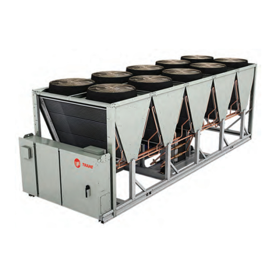
Ascend™ Air-Cooled Chiller —
Model ACS
140 to 230 Nominal Tons
Only qualified personnel should install and service the equipment. The installation, starting up, and servicing of heating, ventilating, and air-conditioning
equipment can be hazardous and requires specific knowledge and training. Improperly installed, adjusted or altered equipment by an unqualified person
could result in death or serious injury. When working on the equipment, observe all precautions in the literature and on the tags, stickers, and labels that
are attached to the equipment.
April 2020
S S A A F F E E T T Y Y W W A A R R N N I I N N G G
A A C C - - S S V V X X 0 0 0 0 2 2 D D - - E E N N
Advertisement
Table of Contents

Subscribe to Our Youtube Channel
Related Manuals for Trane Ascend ACS 140


Summary of Contents for Trane Ascend ACS 140
- Page 1 Installation, Operation, and Maintenance Ascend™ Air-Cooled Chiller — Model ACS 140 to 230 Nominal Tons S S A A F F E E T T Y Y W W A A R R N N I I N N G G Only qualified personnel should install and service the equipment.
- Page 2 A A L L W W A A Y Y S S r r e e f f e e r r t t o o a a p p p p r r o o p p r r i i a a t t e e S S a a f f e e t t y y D D a a t t a a impact to the environment. Trane advocates the...
- Page 3 , , e e l l e e c c t t r r i i c c a a l l , , f f a a l l l l p p r r o o t t e e c c t t i i o o n n , , l l o o c c k k o o u u t t / / property of Trane, and may not be used or reproduced t t a a g g o o u u t t , , r r e e f f r r i i g g e e r r a a n n t t h h a a n n d d l l i i n n g g , , e e t t c c .
-
Page 4: Table Of Contents
Table of Contents Model Number Information ....6 Evaporator Piping Components ..21 Evaporator Label..... 23 Nameplates . - Page 5 Power Up Diagram ....63 Trane Service ......85 Power Up to Starting .
-
Page 6: Model Number Information
Model Number Information Nameplates • Unit model and size description. • Unit serial number. Unit nameplates are applied to the exterior of the control panel. A compressor nameplate is located on • Unit electrical requirements. each compressor. When the unit arrives, compare all •... -
Page 7: Model Number Descriptions
Digit 10— Manufacturing Location B = Convenience Outlet and Under/Over L = Flow Switch Setpoint 60 Voltage Protection U = Trane Commercial Systems, Pueblo, CO Digit 23 — Insulation Digit 33 — Remote Communications Options A = Factory Insulation — All Cold Parts 0.75 Digits 11, 12 —... -
Page 8: Compressor Information
381 = 30 tons 485 = 40 tons Digit 7 — Agency Approval A = UL Digit 8 — Voltage 3 = 200–230V/60Hz/3ph 4 = 460V/60Hz/3ph 7 = 575V/60Hz/3ph Digit 9, 10 — Custom AT = Trane Pueblo AT = Trane Epinal AC-SVX002D-EN... -
Page 9: General Information
General Information Unit Description chiller unit. Adaptive Control logic can correct these variables, when necessary, to optimize operational Ascend™ Model ACS units are scroll type, air-cooled, efficiencies, avoid chiller shutdown, and keep liquid chillers, designed for installation outdoors. Each producing chilled water. Each refrigerant circuit is unit has two independent refrigerant circuits, with two provided with filter, sight glass, electronic expansion or three compressors per circuit. - Page 10 G G e e n n e e r r a a l l I I n n f f o o r r m m a a t t i i o o n n Table 1. General data (I-P) (continued) Unit Size (tons) Avail Head Pressure ft H...
- Page 11 G G e e n n e e r r a a l l I I n n f f o o r r m m a a t t i i o o n n Table 2. General data (SI) Unit Size (tons) Compressor Model Quantity...
-
Page 12: Pre-Installation
Notify the carrier’s terminal of the damage at 70°F (or 145 psig at 50°F), call a qualified service immediately by phone and by mail. organization and the appropriate Trane sales office. • Concealed damage must be reported within 15 N N o o t t e e : : Pressure will be approximately 20 psig if shipped days. -
Page 13: Installation Requirements
(20 psig max per unit as needed) Ascend™ Model ACS Installation Completion Check Sheet and Request for Trane Service (AC-ADF003*-EN) See Log and Check Sheet chapter Trane, or an agent of Trane Chiller Start-up specifically authorized to perform Commissioning start-up of Trane® products AC-SVX002D-EN... -
Page 14: Dimensions And Weights
Dimensions and Weights Unit Dimensions Standard Unit Unit Size 228.9 5513 228.9 5513 281.5 7151 281.5 7151 334.4 8495 334.4 8495.0 225.7 5734 225.7 5734 278.6 7076 278.6 7076 331.4 8418 331.4 8418 48.3 1226 48.3 1226 63.3 1609 63.3 1609 60.4 1535... -
Page 15: Units With Pump Package
D D i i m m e e n n s s i i o o n n s s a a n n d d W W e e i i g g h h t t s s Units with Pump Package Option Unit Size 228.9... -
Page 16: Service Clearance
D D i i m m e e n n s s i i o o n n s s a a n n d d W W e e i i g g h h t t s s Service Clearance Figure 1. -
Page 17: Installation - Mechanical
- - o o n n l l y y d d a a m m a a g g e e . . across the length and width of the unit. The Trane... -
Page 18: Isolation And Sound Emission
I I n n s s t t a a l l l l a a t t i i o o n n - - M M e e c c h h a a n n i i c c a a l l Figure 2. -
Page 19: Unit Isolation And Leveling
I I n n s s t t a a l l l l a a t t i i o o n n - - M M e e c c h h a a n n i i c c a a l l Unit Isolation and Leveling Elastomeric Isolators For additional reduction of sound and vibration, install... - Page 20 I I n n s s t t a a l l l l a a t t i i o o n n - - M M e e c c h h a a n n i i c c a a l l Figure 5.
-
Page 21: Evaporator Piping
I I n n s s t t a a l l l l a a t t i i o o n n - - M M e e c c h h a a n n i i c c a a l l Table 8. - Page 22 I I n n s s t t a a l l l l a a t t i i o o n n - - M M e e c c h h a a n n i i c c a a l l Figure 6.
-
Page 23: Evaporator Label
If the operating conditions on the job site change, the flow switch may need to be replaced. Contact your local Trane Sales office for more information. The sensor head includes 3 LEDs, two yellow and one The flow switch must have the dot in the shaded area to the left of this line green. -
Page 24: Pressure Drop Curves
I I n n s s t t a a l l l l a a t t i i o o n n - - M M e e c c h h a a n n i i c c a a l l Pressure Drop Curves N N o o t t e e : : See General Data tables for limit values for overlapping curves. - Page 25 I I n n s s t t a a l l l l a a t t i i o o n n - - M M e e c c h h a a n n i i c c a a l l Figure 10.
-
Page 26: Pump Curves
I I n n s s t t a a l l l l a a t t i i o o n n - - M M e e c c h h a a n n i i c c a a l l Pump Curves Figure 12. - Page 27 I I n n s s t t a a l l l l a a t t i i o o n n - - M M e e c c h h a a n n i i c c a a l l Figure 14.
-
Page 28: Freeze Avoidance
I I n n s s t t a a l l l l a a t t i i o o n n - - M M e e c c h h a a n n i i c c a a l l Freeze Avoidance N N o o t t e e : : Ascend™... -
Page 29: Low Evaporator Refrigerant Cutout
For information on specific conditions, contact performance. The unit efficiency will be reduced and Trane product support. the saturated evaporator temperature will be reduced. For some operating conditions this effect can be significant. - Page 30 I I n n s s t t a a l l l l a a t t i i o o n n - - M M e e c c h h a a n n i i c c a a l l Table 9.
- Page 31 I I n n s s t t a a l l l l a a t t i i o o n n - - M M e e c c h h a a n n i i c c a a l l Table 10.
-
Page 32: High Head Pump Package
I I n n s s t t a a l l l l a a t t i i o o n n - - M M e e c c h h a a n n i i c c a a l l Table 10. - Page 33 I I n n s s t t a a l l l l a a t t i i o o n n - - M M e e c c h h a a n n i i c c a a l l Figure 17.
-
Page 34: Expansion Tank
I I n n s s t t a a l l l l a a t t i i o o n n - - M M e e c c h h a a n n i i c c a a l l Expansion Tank thermal expansion of a loop volume equivalent to three (3) minute loop at rated flow. -
Page 35: Installation Electrical
Installation Electrical General Recommendations W W A A R R N N I I N N G G H H a a z z a a r r d d o o u u s s V V o o l l t t a a g g e e ! ! As you review this manual, keep in mind that: F F a a i i l l u u r r e e t t o o d d i i s s c c o o n n n n e e c c t t p p o o w w e e r r b b e e f f o o r r e e s s e e r r v v i i c c i i n n g g c c o o u u l l d d •... -
Page 36: Power Supply Wiring
Tracer UC800 activates the pumps. If ambient NEC Table 310-16. temperatures below -4°F are expected, contact your local Trane office. All wiring must comply with local codes and the National Electrical Code. The installing (or electrical) contractor must provide and install the system... -
Page 37: Water Pump Power Supply
I I n n s s t t a a l l l l a a t t i i o o n n E E l l e e c c t t r r i i c c a a l l N N O O T T I I C C E E The relay output is required to operate the Evaporator Water Pump (EWP) contactor. -
Page 38: Relay Assignments Using Tracer Tu
I I n n s s t t a a l l l l a a t t i i o o n n E E l l e e c c t t r r i i c c a a l l 7.2 amps resistive, or 1/3 HP and for 240 VAC circuits Table 15. -
Page 39: Low Voltage Wiring
I I n n s s t t a a l l l l a a t t i i o o n n E E l l e e c c t t r r i i c c a a l l Table 16. -
Page 40: External Chilled/Hot Water Setpoint
I I n n s s t t a a l l l l a a t t i i o o n n E E l l e e c c t t r r i i c c a a l l Communicated input (Tracer) to initiate and command The external water setpoint shall have a configurable the Ice Building mode. -
Page 41: Edls And Echws Analog Input
I I n n s s t t a a l l l l a a t t i i o o n n E E l l e e c c t t r r i i c c a a l l The Tracer®... -
Page 42: Communications Interface
I I n n s s t t a a l l l l a a t t i i o o n n E E l l e e c c t t r r i i c c a a l l maximum rate of 1°F every 5 minutes until the actual N N o o t t e e : : Arbitrated CWS can either be Front Panel, BAS, CWR equals the desired CWR. -
Page 43: Operating Principles
Condenser and Fans The refrigeration cycle of the ACS chiller is The air-cooled microchannel condenser coils use all conceptually similar to other Trane air-cooled chiller aluminum brazed fin construction. The coil is products. The chiller uses a brazed plate evaporator composed of three components: the flat microchannel and an air-cooled MCHE condenser. -
Page 44: Controls
Controls Overview Ascend™ model ACS units utilize the following control/ interface components: • Tracer® UC800 Controller • Tracer AdaptiView™ TD7 Operator Interface UC800 Specifications Wiring and Port Descriptions The following figure illustrates the UC800 controller ports, LEDs, rotary switches, and wiring terminals. The numbered list following the figure corresponds to the numbered callouts in the illustration. -
Page 45: Communication Interfaces
C C o o n n t t r r o o l l s s Figure 20. UC800 wiring locations and connection 5. Power (210 mA at 24 Vdc) and ground terminations ports (same bus as Item 4). Factory wired. 6. - Page 46 C C o o n n t t r r o o l l s s Figure 21. LED locations Table 19. LED behavior UC800 Status Marquee LED Powered. If the Marquee LED is green solid, the UC800 is powered and no problems exist. Low power or malfunction.
-
Page 47: Tracer Adaptiview Td7 Display
C C o o n n t t r r o o l l s s Tracer AdaptiView TD7 Display setpoints, limits, diagnostic information, and reports. This information is provided through the Tracer® Operator Interface AdaptiView™ TD7 display. Logically organized groups of information—... - Page 48 C C o o n n t t r r o o l l s s Table 21. Operating modes — chiller Description Chiller Modes MP Resetting The chiller is not running either circuit, and cannot run without intervention, for instance to Stopped place chiller into the “Auto Mode”...
- Page 49 C C o o n n t t r r o o l l s s Table 21. Operating modes — chiller (continued) Description Chiller Modes Running At least one circuit on the chiller is currently running. Maximum Capacity The chiller is operating at its maximum capacity. Capacity Control Softloading The control is limiting the chiller loading due to capacity based softloading setpoints.
- Page 50 C C o o n n t t r r o o l l s s Table 22. Operating modes — circuit (continued) Description Circuit Modes External Circuit Lockout The respective circuit is manually locked out by External Circuit Lockout switch. Remote Circuit Lockout The respective circuit is manually locked out by a BAS Remote Circuit Lockout command.
-
Page 51: Alarms
C C o o n n t t r r o o l l s s Table 22. Operating modes — circuit (continued) Description Circuit Modes Compressor Sump Heater On The circuit compressor sump heaters are commanded to be energized. Note: Mode strings may or may not include the characters in parentheses. - Page 52 C C o o n n t t r r o o l l s s Figure 28. Report — evaporator screen Table 24. Report — condenser screen items Description Resolution Units Condenser Entering Water Temperature F / C Condenser Leaving Water Temperature F / C Condenser Water Flow...
-
Page 53: Equipment Settings
C C o o n n t t r r o o l l s s Table 25. Report — compressor screen items Figure 32. Equipment settings screen — chiller (continued) settings Description Resolution Units Condenser Refrigerant PSIA/kPaA Pressure XXX.X Differential Refrigerant PSIA/kPaA Pressure... -
Page 54: Display Settings
C C o o n n t t r r o o l l s s Figure 34. Changed chilled water setpoint screen Table 26. Settings screen items (continued) Description Resolution Units Capacity Control Softload Time XXXX Local Atmospheric psi/kPa Pressure XXX.X Power Up Start Delay... - Page 55 C C o o n n t t r r o o l l s s • Unit System • P P r r e e s s s s u u r r e e U U n n i i t t s s –...
-
Page 56: Security Settings
C C o o n n t t r r o o l l s s Figure 38. Date and time settings screen Tracer® TU service tool is used to set an alternate PIN, or to recall a forgotten pin. When defining a PIN in Tracer®... -
Page 57: Invisisound Ultimate - Noise
Tracer® TU serves as a common interface to all Trane® chillers, and will customize itself based on the properties of the chiller with which it is communicating. -
Page 58: Integrated Rapid Restart
C C o o n n t t r r o o l l s s Integrated Rapid Restart N N o o t t e e s s : : • Tracer® TU is designed and validated for Chiller controls are designed and engineered for Rapid this minimum laptop configuration. -
Page 59: Pre-Start
Upon completion of installation, complete the I I m m p p o o r r t t a a n n t t : : Start-up must be performed by Trane or an Installation Completion Check Sheet and Request for... -
Page 60: Start-Up And Shutdown
Trane service organization for more information. I I m m p p o o r r t t a a n n t t : : Initial unit commissioning start-up must be performed by Trane or an agent of Trane specifically authorized to perform start-up Temporary Shutdown And and warranty of Trane products. -
Page 61: Seasonal Unit Start-Up Procedure
F F a a i i l l u u r r e e t t o o f f o o l l l l o o w w i i n n s s t t r r u u c c t t i i o o n n s s b b e e l l o o w w c c o o u u l l d d c c a a u u s s e e present, contact local Trane service. - Page 62 S S t t a a r r t t - - u u p p a a n n d d S S h h u u t t d d o o w w n n evaporator waterbox. start-up as described previously 9.
-
Page 63: Sequence Of Operation
S S t t a a r r t t - - u u p p a a n n d d S S h h u u t t d d o o w w n n Sequence of Operation In the following diagrams: •... -
Page 64: Power Up To Starting
S S t t a a r r t t - - u u p p a a n n d d S S h h u u t t d d o o w w n n Power Up to Starting •... -
Page 65: Stopped To Starting
S S t t a a r r t t - - u u p p a a n n d d S S h h u u t t d d o o w w n n Stopped to Starting •... -
Page 66: Normal Shutdown To Stopped Or
S S t t a a r r t t - - u u p p a a n n d d S S h h u u t t d d o o w w n n Normal Shutdown to Stopped or Run dashed lines on the top attempt to show the final mode if stop is selected via various inputs. -
Page 67: Maintenance
. . 4. Contact a Trane service organization to leak test the... -
Page 68: Refrigerant And Oil Charge
C C o o i i l l D D a a m m a a g g e e ! ! I I m m p p o o r r t t a a n n t t : : If oil level is low, contact your local Trane U U s s e e o o f f d d e e t t e e r r g g e e n n t t s s c c o o u u l l d d c c a a u u s s e e d d a a m m a a g g e e t t o o c c o o i i l l s s . -
Page 69: Repair/Replacement Of Microchannel
Water Strainer Maintenance are not indestructible. When damage or a leak occurs, contact your local Trane office. Units without Pump Package Condenser Coil Corrosion Protection An in-line strainer with a V-shaped sieve is used for... -
Page 70: Units With Pump Package
M M a a i i n n t t e e n n a a n n c c e e for the pressure gauges are included as standard from • Pump port protection plates must not be removed the factory. -
Page 71: Diagnostics
Diagnostics General Diagnostics Information has a special action defined in the table below, it will be displayed only as "Informational Warning" as long as D D i i a a g g n n o o s s t t i i c c N N a a m m e e a a n n d d S S o o u u r r c c e e : : Diagnostics may be no circuit or chiller shutdown results. - Page 72 D D i i a a g g n n o o s s t t i i c c s s Table 29. Main process diagnostics (continued) Active Affects Modes Diagnostic Reset Severity Persistence Criteria Target [Inactive Name Level Modes] The circuit’s suction pressure dropped below (Low Pressure Cutout Setpoint (kPa absolute) * 0.5)
- Page 73 D D i i a a g g n n o o s s t t i i c c s s Table 29. Main process diagnostics (continued) Active Affects Modes Diagnostic Reset Severity Persistence Criteria Target [Inactive Name Level Modes] The BAS was setup as "installed"...
- Page 74 D D i i a a g g n n o o s s t t i i c c s s Table 29. Main process diagnostics (continued) Active Affects Modes Diagnostic Reset Severity Persistence Criteria Target [Inactive Name Level Modes] Not Enabled (Default): diagnostic is Non-Latching and Warning.
- Page 75 D D i i a a g g n n o o s s t t i i c c s s Table 29. Main process diagnostics (continued) Active Affects Modes Diagnostic Reset Severity Persistence Criteria Target [Inactive Name Level Modes] Either the leaving or the entering water temperature exceeded the high evap water temp setting (TU...
- Page 76 D D i i a a g g n n o o s s t t i i c c s s Table 29. Main process diagnostics (continued) Active Affects Modes Diagnostic Reset Severity Persistence Criteria Target [Inactive Name Level Modes] A counter for evaporator pump 2 starts or hours has Evaporator...
- Page 77 D D i i a a g g n n o o s s t t i i c c s s Table 29. Main process diagnostics (continued) Active Affects Modes Diagnostic Reset Severity Persistence Criteria Target [Inactive Name Level Modes] For systems with no evaporator pump, a single evaporator pump, or a single inverter driving dual...
-
Page 78: Sensor Failure Diagnostic
D D i i a a g g n n o o s s t t i i c c s s Sensor Failure Diagnostic is no longer sending a valid value to the Main Processor, indicating a sensor failure. N N o o t t e e s s : : Some LLIDs may have more than one 1. -
Page 79: Communication Diagnostics
D D i i a a g g n n o o s s t t i i c c s s Communication Diagnostics Name of the input or output that is no longer being heard from by the Main Processor. N N o o t t e e s s : : Many LLIDs, such as the Quad Relay LLID, 1. - Page 80 D D i i a a g g n n o o s s t t i i c c s s Table 31. Communication diagnostics (continued) Active Affects Modes Diagnostic Reset Severity Persistence Criteria Target [Inactive Name Level Modes] Continual loss of communication between the MP and Comm Loss: the Functional ID has occurred for a 35-40 second...
- Page 81 D D i i a a g g n n o o s s t t i i c c s s Table 31. Communication diagnostics (continued) Active Affects Modes Diagnostic Reset Severity Persistence Criteria Target [Inactive Name Level Modes] Comm Loss: Continual loss of communication between the MP and Evaporator...
- Page 82 D D i i a a g g n n o o s s t t i i c c s s Table 31. Communication diagnostics (continued) Active Affects Modes Diagnostic Reset Severity Persistence Criteria Target [Inactive Name Level Modes] Comm Loss: Continual loss of communication between the MP and Percent...
-
Page 83: Unit Wiring
Unit Wiring The following table provides a list of electrical AC-SVE002*-EN. A laminated wiring diagram booklet is schematics, field wiring diagrams and connection also shipped with each unit. diagrams. Complete wiring package is documented in Description Document Number Sheet 1 Table of Contents Legend Sheet 2... -
Page 84: Log And Check Sheets
Ascend™ Model ACS Installation Completion Check installation completion verification before Trane start- Sheet and Request for Trane Service (AC-ADF003*- up is scheduled, and for reference during the Trane start-up. Where the log or check sheet also exists • Operator Log outside of this publication as standalone literature, the literature order number is also listed. - Page 85 ☐ Flow balancing valves installed on leaving I I m m p p o o r r t t a a n n t t : : Start-up must be performed by Trane or an chilled water agent of Trane specifically authorized to perform start-up and warranty of Trane®...
- Page 86 20 = 1), e e n n e e r r g g i i z z e e h h e e a a t t e e r r s s f f o o r r 2 2 4 4 h h o o u u r r s s p p r r i i o o r r t t o o require the presence of Trane service on this site, for s s t t a a r r t t u u p p .
- Page 87 N N o o t t e e s s AC-SVX002D-EN...
- Page 88 For more information, please visit trane.com or tranetechnologies.com. Trane has a policy of continuous product and product data improvements and reserves the right to change design and specifications without notice. We are committed to using environmentally conscious print practices.
Need help?
Do you have a question about the Ascend ACS 140 and is the answer not in the manual?
Questions and answers