Table of Contents
Advertisement
Installation, Operation, and Maintenance
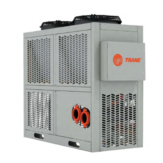
Manhattan™ Gen II Air-Cooled
Modular Chiller
Only qualified personnel should install and service the equipment. The installation, starting up, and servicing of
heating, ventilating, and air-conditioning equipment can be hazardous and requires specific knowledge and training.
Improperly installed, adjusted or altered equipment by an unqualified person could result in death or serious injury.
When working on the equipment, observe all precautions in the literature and on the tags, stickers, and labels that are
attached to the equipment.
December 2021
SAFETY WARNING
ARTC-SVX001B-EN
Advertisement
Table of Contents

Subscribe to Our Youtube Channel
Related Manuals for Trane Arctic Manhattan Gen II


Summary of Contents for Trane Arctic Manhattan Gen II
- Page 1 Installation, Operation, and Maintenance Manhattan™ Gen II Air-Cooled Modular Chiller SAFETY WARNING Only qualified personnel should install and service the equipment. The installation, starting up, and servicing of heating, ventilating, and air-conditioning equipment can be hazardous and requires specific knowledge and training. Improperly installed, adjusted or altered equipment by an unqualified person could result in death or serious injury.
- Page 2 A A L L W W A A Y Y S S r r e e f f e e r r t t o o a a p p p p r r o o p p r r i i a a t t e e S S a a f f e e t t y y D D a a t t a a impact to the environment. Trane advocates the...
- Page 3 This document and the information in it are the property of Trane, and may not be used or reproduced F F a a i i l l u u r r e e t t o o f f o o l l l l o o w w i i n n s s t t r r u u c c t t i i o o n n s s b b e e l l o o w w c c o o u u l l d d r r e e s s u u l l t t i i n n in whole or in part without written permission.
-
Page 4: Table Of Contents
Table of Contents Model Number Descriptions....6 Phase Monitor Installation ... . 20 Power Interlock Switch ....20 Model Number and Coding. - Page 5 T T a a b b l l e e o o f f C C o o n n t t e e n n t t s s Maintain Glycol Level ....38 Pump Tasks .
-
Page 6: Model Number Descriptions
Model Number Descriptions Digit 1— Brand Digit 14, 15 — Chiller Application T = Trane MM = Modular Digit 2 — Model Series Digit 16, 17 — Additional Features P = Process and Modular Series VS = Variable Speed VS1 = Variable Speed (1 Compressor) VS2 = Variable Speed (2 Compressors) Digit 3, 4, 5 —... -
Page 7: Model Number And Coding
Chiller Reference Data. Refer to the Trane the model number and serial number of the chiller nameplate on each module in the installed unit for the modules in question. -
Page 8: Chiller Description
Standard interconnecting headers are composed of This manual provides relevant data to properly carbon steel. operate, maintain, and troubleshoot the Trane Water quality must be monitored and maintained by a Manhattan™ Gen IIAir-Cooled Modular Chiller. water treatment professional familiar with the... -
Page 9: Optional Tank And Pump Module
C C h h i i l l l l e e r r D D e e s s c c r r i i p p t t i i o o n n Evaporator The brazed plate evaporator is constructed as corrugated channel plates with filler material between each plate. -
Page 10: Pre-Installation
N N o o t t e e : : If Trane pumps are provided, check that each pump’s overload setting matches the Ensure there is a sufficient cooling load available for nameplate amperage of the pumps as proper testing of the chiller system. - Page 11 Check the box if there are any customer-supplied devices connected to the chiller wiring. ☐ List devices: ______________________________________________________________________________________ Check the box if there are any Trane remote devices connected to the chiller wiring. ☐ Check the box if voltage drops are detected.
-
Page 12: Startup
☐ Note: To view the software version, from the home screen, press the software button on the System Control screen. Startup As part of a continuous commitment to quality, initial startup of this chiller must be done by Trane. ARTC-SVX001B-EN... -
Page 13: Installation Mechanical
Any damage procedures have been completed and any deviations must be reported to the motor carrier and Trane within are reported to Trane immediately. five days of receipt of the shipment. -
Page 14: Customer Responsibilities
I I n n s s t t a a l l l l a a t t i i o o n n M M e e c c h h a a n n i i c c a a l l Trane will document and photograph the status of the... -
Page 15: Minimum Clearances
Avoid air recirculation from other nearby walls, fences, overhanging roof eaves, or is located in a equipment. Locate the condenser away from building pit (sub-level site), contact Trane to discuss potential air vents and heat sources such as exhaust fans. impact on equipment performance. - Page 16 I I n n s s t t a a l l l l a a t t i i o o n n M M e e c c h h a a n n i i c c a a l l N N o o t t e e : : These clearances are general recommendations. Contact Trane for definitive guidance and Each installation has specific considerations.
-
Page 17: Rigging, Lifting, And Moving The Chiller
I I n n s s t t a a l l l l a a t t i i o o n n M M e e c c h h a a n n i i c c a a l l Rigging, Lifting, and Moving the •... -
Page 18: Mounting Rails
I I n n s s t t a a l l l l a a t t i i o o n n M M e e c c h h a a n n i i c c a a l l Mounting Rails All of the modules arrive with labels on the electrical and control panel. -
Page 19: Installation Piping
Installation Piping Install Piping and External weight inside the pipes. A 40-mesh screen strainer must be installed in each water/liquid system piping Components inlet for proper filtration an protection of the heat exchangers. The following figure provides a Proper support of piping and pipe hangers must recommended installation of components. -
Page 20: Installation Electrical
Installation Electrical Connecting Module Power and at the mounting socket. No further adjustment should be required. Control Wires Power Interlock Switch Connections are made at the primary module, which typically contains the power distribution panel (or on Some Manhattan™ Gen II Chiller systems are the tank and pump module, if so equipped). -
Page 21: Operating Principles
Operating Principles The Manhattan™ Gen II Air-Cooled Modular Chiller is refrigerant to the evaporator where it evaporates and designed to operate with a water/glycol mixture to the heat in the system water/glycol mixture transfers to prevent rust, scaling, and organic growth. the refrigerant. -
Page 22: Operating Procedures
Operating Procedures Operator Interface Panel-Mounted Disconnect Switch SomeManhattan™ Gen II Chiller systems are optionally Manhattan™ Gen II Air-Cooled Modular Chiller units, equipped with a panel-mounted disconnect switch whether they are composed of a single module or up to installed on the outside of the power distribution panel 10 modules, are automated systems that use a main (or on each module’s electrical and control panel if the electrical panel to monitor, report, and modify critical... -
Page 23: Panel
O O p p e e r r a a t t i i n n g g P P r r o o c c e e d d u u r r e e s s Module Electrical and Control Panel also has fuses and breakers, compressor switches, and the microprocessor controller. -
Page 24: Operating The Microprocessor
The touchscreen interface panel is ready to use when it the technician (‘tech’) and administrator (‘admin’) is connected to the Ethernet switch and chiller power is levels that can only be accessed by Trane technical personnel. Contact Trane technical support regarding the possibility of any potential issues involving the Upon initial startup, the status line will indicate that the higher-level functions. -
Page 25: Touchscreen Interface Panel
O O p p e e r r a a t t i i n n g g P P r r o o c c e e d d u u r r e e s s Touchscreen Interface Panel Ethernet switch. -
Page 26: Interface Menu Structure
O O p p e e r r a a t t i i n n g g P P r r o o c c e e d d u u r r e e s s Interface Menu Structure Key interface screens are organized according to system, primary module, and secondary modules functions. -
Page 27: Hmi Functions
O O p p e e r r a a t t i i n n g g P P r r o o c c e e d d u u r r e e s s HMI Functions Figure 13. -
Page 28: Modules Layout Screen
O O p p e e r r a a t t i i n n g g P P r r o o c c e e d d u u r r e e s s • No Evap Flow. System is off by absence of to all chiller modules screens individually. -
Page 29: Active Alarms Screen
O O p p e e r r a a t t i i n n g g P P r r o o c c e e d d u u r r e e s s Table 3. Module status conditions Module turned off by alarm and unavailable Module is available Module is unavailable... -
Page 30: Alarm History
O O p p e e r r a a t t i i n n g g P P r r o o c c e e d d u u r r e e s s Reset • TRIGGERED (ACTIVE) / NOT ACKNOWLEDGED •... -
Page 31: Modules Overview Screens
O O p p e e r r a a t t i i n n g g P P r r o o c c e e d d u u r r e e s s Event Type The alarm history screen displays the history of alarms recorded by the primary microprocessor (See Figure... -
Page 32: Overview Module
O O p p e e r r a a t t i i n n g g P P r r o o c c e e d d u u r r e e s s Table 4. The overview screens Secondary Overview Module Screen Primary Overview Module Screen Primary/Secondary Overview Circuit Screen... -
Page 33: Overview Circuits
O O p p e e r r a a t t i i n n g g P P r r o o c c e e d d u u r r e e s s Overview Circuits 2. -
Page 34: Analog Inputs
O O p p e e r r a a t t i i n n g g P P r r o o c c e e d d u u r r e e s s Table 5. The input/output screens Primary/Seconday I/O Digital Screen Primary/Seconday I/O Analog Screen Primary/Seconday I/O Expansion Screen... -
Page 35: Analog Outputs
O O p p e e r r a a t t i i n n g g P P r r o o c c e e d d u u r r e e s s AI11 DI opened - pressure is exceeding normal range threshold (faulty state). -
Page 36: Expansion Io Screen
O O p p e e r r a a t t i i n n g g P P r r o o c c e e d d u u r r e e s s DO10 General Alarm This digital output energizes when any of the following This is the feedback for Pump-down pressure switch of alarms occur:... -
Page 37: Operator Tasks
O O p p e e r r a a t t i i n n g g P P r r o o c c e e d d u u r r e e s s Normal Power Up 1. -
Page 38: Emergency Power Shutdown
N N o o t t e e : : Trane will not validate the chiller warranty if the electrical and control panel. This action sends a proper water/glycol mixture composition and command to the controller in each module’s... -
Page 39: Prevent Freezing
In order to maintain a high quality glycol solution, the that protect piping and components from corrosion water used in the glycol mixture must have very few and buildup of rust and other deposits. Trane impurities. Impurities in the water can increase metal recommends against using water/glycol solution in... - Page 40 O O p p e e r r a a t t i i n n g g P P r r o o c c e e d d u u r r e e s s indicated in Figure 19, p.
-
Page 41: Controls Interface
Controls Interface Microprocessor Control System Figure 21. Touch interface panel Manhattan™ Gen II Chiller models employ a Carel c. pCO all-digital data control system to control and report key system settings and indicators. Primary Microprocessor Controller Both the primary and secondary modules use a Carel c. pCO medium microprocessor controller. -
Page 42: Electrical Controls
C C o o n n t t r r o o l l s s I I n n t t e e r r f f a a c c e e Main Power Distribution Figure 23. Module electrical and control panel The power distribution panel distributes electricity from the external building power supply. -
Page 43: Refrigeration Controls
C C o o n n t t r r o o l l s s I I n n t t e e r r f f a a c c e e Expansion Valve N N O O T T I I C C E E An expansion valve is a metering device controlling the P P r r o o o o f f o o f f F F l l o o w w S S w w i i t t c c h h ! ! flow of refrigerant to the evaporator based on... - Page 44 E E q q u u i i p p m m e e n n t t D D a a m m a a g g e e ! ! mixture, contact Trane technical support for proper set F F a a i i l l u u r r e e t t o o r r e e m m o o v v e e m m o o i i s s t t u u r r e e f f r r o o m m s s y y s s t t e e m m c c o o u u l l d d points.
-
Page 45: Sequence Of Operations
Sequence of Operations This manual describes a typical air-cooled chiller 11. If power is removed and then returned to a chiller system with few, if any, optional components or system (i.e. power failure), the compressors will devices attached. To cover the primary difference in restart every five seconds for the next five minutes construction and operation, two sequences of as needed. - Page 46 S S e e q q u u e e n n c c e e o o f f O O p p e e r r a a t t i i o o n n s s the pump can provide the minimum flow required 12.
-
Page 47: Chiller Performance Data
Chiller Performance Data This manual uses a typical 120-ton air-cooled chiller and a chiller’s precise electrical and refrigerant data consisting of four modules with brazed plate can be found on the chiller model nameplate. See evaporators for example purposes. The model number “Model Number and Coding,”... -
Page 48: Maintenance Procedures
Maintenance for HVAC equipment and facilities can down time. Trane chillers are designed for ease of include a “preventive maintenance checklist” which access with a premium placed on locating key includes small checks which can significantly extend components to facilitate visual inspection and hands- service life. -
Page 49: Federal Clean Air Act
M M a a i i n n t t e e n n a a n n c c e e P P r r o o c c e e d d u u r r e e s s N N O O T T I I C C E E additional requirements that must be followed to responsibly handle HVAC refrigerants. -
Page 50: Weekly
M M a a i i n n t t e e n n a a n n c c e e P P r r o o c c e e d d u u r r e e s s Table 10. -
Page 51: Quarterly
M M a a i i n n t t e e n n a a n n c c e e P P r r o o c c e e d d u u r r e e s s N N O O T T I I C C E E 8. -
Page 52: Tasks
M M a a i i n n t t e e n n a a n n c c e e P P r r o o c c e e d d u u r r e e s s Pump and Tank Maintenance Tasks 2. -
Page 53: Critical Cleaning Tasks
Apply a light coating of lubrication to the cleaning. gasket. On multiple module chillers, Trane provides service 8. Re-install the strainer in the housing (large end isolation valves on each evaporator to isolate each first). Replace the gasket and end cap and tighten strainer for cleaning without disrupting the operation coupling collar securely. -
Page 54: Compressor Tasks
. . F F o o l l l l o o w w p p r r o o p p e e r r build-up. Trane recommends using straight tap l l o o c c k k o o u u t t / / t t a a g g o o u u t t p p r r o o c c e e d d u u r r e e s s t t o o e e n n s s u u r r e e t t h h e e p p o o w w e e r r water except in extreme cases. -
Page 55: Pump Tasks
M M a a i i n n t t e e n n a a n n c c e e P P r r o o c c e e d d u u r r e e s s 4. - Page 56 M M a a i i n n t t e e n n a a n n c c e e P P r r o o c c e e d d u u r r e e s s Replace Pump Seal 1.
-
Page 57: Controller Tasks
M M a a i i n n t t e e n n a a n n c c e e P P r r o o c c e e d d u u r r e e s s 12. -
Page 58: Chiller Troubleshooting
Isolation Fault detection is recognizing that a problem has Trane manufactures chillers with embedded fault occurred, even if the root cause is not yet known. Fault detection and diagnostics in each module’s controller... -
Page 59: Compressor Diagnostic Codes
T T R R I I P P is indicated by a solid illumination of the LED. This means the compressor is not running and Copeland compressors used in Trane chillers are highly demand is present at the module. automated with digital capability to record and report a •... - Page 60 C C h h i i l l l l e e r r T T r r o o u u b b l l e e s s h h o o o o t t i i n n g g trip condition lasting longer than 7 minutes.
-
Page 61: Variable Frequency Drive Diagnostic
C C h h i i l l l l e e r r T T r r o o u u b b l l e e s s h h o o o o t t i i n n g g Variable Frequency Drive Diagnostic Indicators Diagnostic Codes (Optional) -
Page 62: Phase Monitor Protection
C C h h i i l l l l e e r r T T r r o o u u b b l l e e s s h h o o o o t t i i n n g g Figure 25. - Page 63 C C h h i i l l l l e e r r T T r r o o u u b b l l e e s s h h o o o o t t i i n n g g 1.
- Page 64 C C h h i i l l l l e e r r T T r r o o u u b b l l e e s s h h o o o o t t i i n n g g 6.
- Page 65 C C h h i i l l l l e e r r T T r r o o u u b b l l e e s s h h o o o o t t i i n n g g 9.
- Page 66 C C h h i i l l l l e e r r T T r r o o u u b b l l e e s s h h o o o o t t i i n n g g 13.
-
Page 67: Variable Frequency Drive Fault Codes
C C h h i i l l l l e e r r T T r r o o u u b b l l e e s s h h o o o o t t i i n n g g Variable Frequency Drive Fault not latch and the drive will continue to operate the motor. - Page 68 C C h h i i l l l l e e r r T T r r o o u u b b l l e e s s h h o o o o t t i i n n g g Code (hex) Fault / Aux.
- Page 69 C C h h i i l l l l e e r r T T r r o o u u b b l l e e s s h h o o o o t t i i n n g g Code (hex) Fault / Aux.
- Page 70 C C h h i i l l l l e e r r T T r r o o u u b b l l e e s s h h o o o o t t i i n n g g Code (hex) Fault / Aux.
- Page 71 C C h h i i l l l l e e r r T T r r o o u u b b l l e e s s h h o o o o t t i i n n g g Code (hex) Fault / Aux.
- Page 72 C C h h i i l l l l e e r r T T r r o o u u b b l l e e s s h h o o o o t t i i n n g g Code (hex) Fault / Aux.
- Page 73 C C h h i i l l l l e e r r T T r r o o u u b b l l e e s s h h o o o o t t i i n n g g Code (hex) Fault / Aux.
-
Page 74: Logical Flow Diagrams
Logical Flow Diagrams The following section presents the simplified logical configurations to meet the demands of a worldwide flow block diagrams for the principal systems in the market. The high voltage configuration for a chiller Manhattan™ Gen II Air-Cooled Modular Chiller. module is listed on each module’s name plate. -
Page 75: Control Logical Flow
L L o o g g i i c c a a l l F F l l o o w w D D i i a a g g r r a a m m s s Figure 27. High voltage logical flow of chiller bank Control Logical Flow The chiller uses low voltage for controller and sensor circuits. - Page 76 L L o o g g i i c c a a l l F F l l o o w w D D i i a a g g r r a a m m s s Figure 29. Control logical flow ARTC-SVX001B-EN...
-
Page 77: Refrigeration Logical Flow
See below figure. Figure 30. Refrigeration logical flow Water/Glycol Mixture Logical used within a closed system as shown in the following figure. Flow Trane recommends using a water/glycol mixture instead of an all water fluid. The water/glycol mixture is ARTC-SVX001B-EN... - Page 78 L L o o g g i i c c a a l l F F l l o o w w D D i i a a g g r r a a m m s s Figure 31. Water/glycol mixture logical flow ARTC-SVX001B-EN...
-
Page 79: Acronyms And Abbreviations
Appendix A. Acronyms and Abbreviations All acronyms and abbreviations used in this manual, Table 16. Acronyms and abbreviations (continued) on the chiller controllers, and on module indicators and Expansion Item gauges are listed in the following tables. Electromagnetic Compatibility Electromagnetic Interference Acronym List Extended Performance Compressor EvapFl... - Page 80 A A c c r r o o n n y y m m s s a a n n d d A A b b b b r r e e v v i i a a t t i i o o n n s s Table 16.
-
Page 81: Tank And Pump Module
Appendix B. Tank and Pump Module Tank and Pump be exploited. The sealed tank also contains a vacuum vent to protect the tank from imploding. Components Dual lead/lag pumps, each with 100% pumping capacity, are provided in each tank and pump module. A tank and pump module typically contains dual lead/ If the lead pump fails to operate, the lag pump activates lag pumps and an expansion tank. -
Page 82: Fill The Storage Tank
T T a a n n k k a a n n d d P P u u m m p p M M o o d d u u l l e e Fill the Storage Tank valves which are controlled based on leaving water temperature. - Page 83 T T a a n n k k a a n n d d P P u u m m p p M M o o d d u u l l e e 12. This process occurs throughout the operating range 14.
-
Page 84: Request For Initial Startup
To prevent additional charges for aborted startups, the following items must be completely functional and operating and this form signed and returned to Trane at least 10 working days prior to the As part of a continuous commitment to quality, initial scheduled initial startup date. -
Page 85: Initial Startup Agreement
R R e e q q u u e e s s t t f f o o r r I I n n i i t t i i a a l l S S t t a a r r t t u u p p Initial Startup Agreement designated startup technician. - Page 86 N N o o t t e e s s ARTC-SVX001B-EN...
- Page 87 N N o o t t e e s s ARTC-SVX001B-EN...
- Page 88 For more information, please visit www.arcticchillergroup.com. Trane has a policy of continuous product and product data improvement and reserves the right to change design and specifications without notice. We are committed to using environmentally conscious print practices.
Need help?
Do you have a question about the Arctic Manhattan Gen II and is the answer not in the manual?
Questions and answers