Table of Contents
Advertisement
Quick Links
Installation, Operation,
and Maintenance
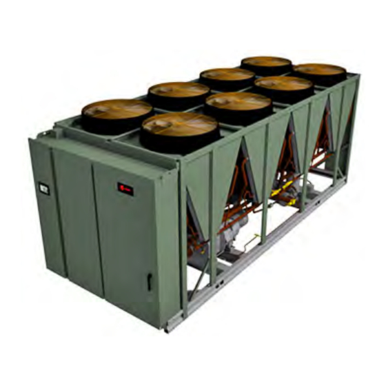
Ascend™ ™ Air-Cooled Chiller — Model ACR
With AdaptiSpeed™ Technology
Quiet operation enabled by InvisiSound™ Technology
150 to 300 Nominal Tons
Only qualified personnel should install and service the equipment. The installation, starting up, and servicing of heating, ventilating, and
air-conditioning equipment can be hazardous and requires specific knowledge and training. Improperly installed, adjusted or altered
equipment by an unqualified person could result in death or serious injury. When working on the equipment, observe all precautions in the
literature and on the tags, stickers, and labels that are attached to the equipment.
March 2019
S S A A F F E E T T Y Y W W A A R R N N I I N N G G
A A C C - - S S V V X X 0 0 0 0 1 1 A A - - E E N N
Advertisement
Table of Contents

Related Manuals for Trane Ascend ACR Series


Summary of Contents for Trane Ascend ACR Series
- Page 1 Installation, Operation, and Maintenance Ascend™ ™ Air-Cooled Chiller — Model ACR With AdaptiSpeed™ Technology Quiet operation enabled by InvisiSound™ Technology 150 to 300 Nominal Tons S S A A F F E E T T Y Y W W A A R R N N I I N N G G Only qualified personnel should install and service the equipment.
- Page 2 A A L L W W A A Y Y S S r r e e f f e e r r t t o o a a p p p p r r o o p p r r i i a a t t e e M M a a t t e e r r i i a a l l S S a a f f e e t t y y impact to the environment. Trane advocates the...
- Page 3 , , t t h h o o s s e e r r e e g g u u l l a a t t i i o o n n s s s s u u p p e e r r s s e e d d e e property of Trane, and may not be used or reproduced t t h h e e s s e e p p o o l l i i c c i i e e s s .
-
Page 4: Table Of Contents
Table of Contents Model Number Information ....7 Mounting Locations, Weights, Isolators......27 Nameplates . - Page 5 T T a a b b l l e e o o f f C C o o n n t t e e n n t t s s LonTalk Interface (LCI-C) ... . . 47 Sequence of Operation.
- Page 6 Main Processor Diagnostics ....87 Trane Service ......106 Communication Diagnostics.
-
Page 7: Model Number Information
• Unit electrical requirements. each compressor. When the unit arrives, compare all • Operating charges of R-134a and refrigerant oil nameplate data with ordering, submittal, and shipping (Trane OIL00311). information. • Unit test pressures. Unit Nameplate • Installation, operation and maintenance and service data literature. -
Page 8: Model Number Descriptions
Digit 9 — Manufacturing Location Digit 30 — Electrical Accessories X = Grooved Pipe U = Trane Commercial Systems, Pueblo, CO 0 = No Convenience Outlet F = Grooved Pipe + Flange C = 15A 115V Convenience Outlet (Type B) Digits 10, 11 —... - Page 9 M M o o d d e e l l N N u u m m b b e e r r D D e e s s c c r r i i p p t t i i o o n n s s Digit 33 —...
-
Page 10: Compressor Information
M M o o d d e e l l N N u u m m b b e e r r D D e e s s c c r r i i p p t t i i o o n n s s Compressor Information Serial Number Digit 1, 2 —... -
Page 11: General Information
Every unit is electrically tested for proper control operation before shipment. Chilled water inlet and outlet openings are covered for shipment. The chiller features Trane’s exclusive Adaptive Control™ logic, which monitors the control variables that govern the operation of the chiller unit. -
Page 12: General Data
G G e e n n e e r r a a l l I I n n f f o o r r m m a a t t i i o o n n General Data Table 1. General data table Unit Size (tons) Compressor Model CHHSR... - Page 13 32 to 125 (0 to 52) °F (°C) 0 to 125 (-17.7 to 52) Wide Ambient General Unit Refrigerant HFC-134a Refrigerant Ckts Minimum Load (lbs) Refrigerant Charge/ckt (kg) Trane OIL00311 (gal) Oil Charge/ckt 11.4 11.4 11.4 11.4 15.1 15.1 15.1 15.1 AC-SVX001A-EN...
-
Page 14: Drive Cooling Fluid
N N O O T T I I C C E E corrosion or freezing. The Trane Company warranty specifically excludes liability for E E q q u u i i p p m m e e n n t t D D a a m m a a g g e e ! ! -
Page 15: Pre-Installation
If it is not, contact a • Take photos of the damage, if possible. qualified service organization and the appropriate • The owner must provide reasonable evidence that Trane sales office. the damage did not occur after delivery. AC-SVX001A-EN... -
Page 16: Installation Requirements
• Meet foundation requirements Foundation • Safety chains • Clevis connectors Rigging • Lifting beam • Spreader bar Trane, or an agent of Trane specifically authorized to Disassembly/Reassembly perform start-up of Trane® (as required) products (contact your local Trane office for pricing) Elastomeric isolators •... -
Page 17: Dimensions And Weights
Dimensions and Weights Weights Table 3. Unit weights Standard Length Extended Length Shipping Operating Shipping Operating Unit Size (tons) InvisiSound™ Standard or Superior 11333 5141 11479 5207 13492 6120 13638 6186 12377 5614 12533 5685 14532 6592 14688 6662 12698 5760 12881 5843... -
Page 18: Service Clearance
D D i i m m e e n n s s i i o o n n s s a a n n d d W W e e i i g g h h t t s s Service Clearance Figure 3. -
Page 19: Unit Dimensions
D D i i m m e e n n s s i i o o n n s s a a n n d d W W e e i i g g h h t t s s Unit Dimensions Figure 4. - Page 20 D D i i m m e e n n s s i i o o n n s s a a n n d d W W e e i i g g h h t t s s AC-SVX001A-EN...
- Page 21 D D i i m m e e n n s s i i o o n n s s a a n n d d W W e e i i g g h h t t s s Figure 5.
- Page 22 D D i i m m e e n n s s i i o o n n s s a a n n d d W W e e i i g g h h t t s s AC-SVX001A-EN...
-
Page 23: Installation Mechanical
- - o o n n l l y y d d a a m m a a g g e e . . across the length and width of the unit. The Trane... - Page 24 I I n n s s t t a a l l l l a a t t i i o o n n M M e e c c h h a a n n i i c c a a l l N N O O T T I I C C E E I I m m p p o o r r t t a a n n t t : : •...
- Page 25 I I n n s s t t a a l l l l a a t t i i o o n n M M e e c c h h a a n n i i c c a a l l Figure 8.
-
Page 26: Center Of Gravity
I I n n s s t t a a l l l l a a t t i i o o n n M M e e c c h h a a n n i i c c a a l l Center of Gravity Figure 10. - Page 27 I I n n s s t t a a l l l l a a t t i i o o n n M M e e c c h h a a n n i i c c a a l l Figure 11.
- Page 28 I I n n s s t t a a l l l l a a t t i i o o n n M M e e c c h h a a n n i i c c a a l l Table 7.
- Page 29 I I n n s s t t a a l l l l a a t t i i o o n n M M e e c c h h a a n n i i c c a a l l Table 9.
-
Page 30: Compressor Mounting Bolt
I I n n s s t t a a l l l l a a t t i i o o n n M M e e c c h h a a n n i i c c a a l l Table 11. -
Page 31: Refrigerant Pressure Relief Valves
I I n n s s t t a a l l l l a a t t i i o o n n M M e e c c h h a a n n i i c c a a l l Refrigerant Pressure Relief Relief Connection Size (in) -
Page 32: Evaporator Piping Components
I I n n s s t t a a l l l l a a t t i i o o n n M M e e c c h h a a n n i i c c a a l l •... - Page 33 I I n n s s t t a a l l l l a a t t i i o o n n M M e e c c h h a a n n i i c c a a l l • Shutoff (isolation) valves. flow switch may need to be replaced. Contact your local Trane Sales office for more information. • Thermometers. The sensor head includes 3 LEDs, two yellow and one •...
-
Page 34: Evaporator Waterside Pressure Drop
I I n n s s t t a a l l l l a a t t i i o o n n M M e e c c h h a a n n i i c c a a l l Evaporator Waterside Pressure Drop Curves Figure 17. -
Page 35: Freeze Protection
I I n n s s t t a a l l l l a a t t i i o o n n M M e e c c h h a a n n i i c c a a l l Freeze Protection from ambient freeze damage. - Page 36 I I n n s s t t a a l l l l a a t t i i o o n n M M e e c c h h a a n n i i c c a a l l N N O O T T I I C C E E E E v v a a p p o o r r a a t t o o r r D D a a m m a a g g e e ! ! F F a a i i l l u u r r e e t t o o f f o o l l l l o o w w t t h h e e s s e e i i n n s s t t r r u u c c t t i i o o n n s s c c o o u u l l d d r r e e s s u u l l t t i i n n...
-
Page 37: Low Evaporator Refrigerant Cutout
For information on specific conditions, contact performance. The unit efficiency will be reduced and Trane product support. the saturated evaporator temperature will be reduced. For some operating conditions this effect can be significant. -
Page 38: Installation Electrical
Installation Electrical General Recommendations W W A A R R N N I I N N G G H H a a z z a a r r d d o o u u s s V V o o l l t t a a g g e e - - P P r r e e s s s s u u r r i i z z e e d d As you review this manual, keep in mind that: F F l l a a m m m m a a b b l l e e F F l l u u i i d d ! ! •... -
Page 39: Adaptive Frequency™ Drive
I I n n s s t t a a l l l l a a t t i i o o n n E E l l e e c c t t r r i i c c a a l l W W A A R R N N I I N N G G Figure 19. -
Page 40: Power Supply Wiring
I I n n s s t t a a l l l l a a t t i i o o n n E E l l e e c c t t r r i i c c a a l l •... -
Page 41: Control Power Supply
I I n n s s t t a a l l l l a a t t i i o o n n E E l l e e c c t t r r i i c c a a l l Figure 21. -
Page 42: Heater Power Supply
I I n n s s t t a a l l l l a a t t i i o o n n E E l l e e c c t t r r i i c c a a l l LLIDs. -
Page 43: Programmable Relays
I I n n s s t t a a l l l l a a t t i i o o n n E E l l e e c c t t r r i i c c a a l l though there was a zero time delay. -
Page 44: Low Voltage Wiring
I I n n s s t t a a l l l l a a t t i i o o n n E E l l e e c c t t r r i i c c a a l l External Circuit Lockout –... -
Page 45: (Ecws) Option
I I n n s s t t a a l l l l a a t t i i o o n n E E l l e e c c t t r r i i c c a a l l Upon contact closure, the UC800 will initiate an ice diagnostic and the unit will default to using the ront building mode, in which the unit runs fully loaded at all... -
Page 46: Chilled Water Reset (Cwr)
I I n n s s t t a a l l l l a a t t i i o o n n E E l l e e c c t t r r i i c c a a l l Custom Tab of the Configuration View within Tracer Reset, or Constant Return Water Temperature Reset. -
Page 47: Transformer Power Rating
I I n n s s t t a a l l l l a a t t i i o o n n E E l l e e c c t t r r i i c c a a l l the desired CWS'. -
Page 48: Operating Principles
R-134a as designated on the unit nameplate. I I m m p p o o r r t t a a n n t t : : Use only R-134a and Trane Oil 00311 (bulk)/ 00315 (1gal)/00317 (5gal) . Compressor and Oil System... -
Page 49: Evaporator
O O p p e e r r a a t t i i n n g g P P r r i i n n c c i i p p l l e e s s an integral subcooling circuit. Condensers are factory psig. -
Page 50: Controls
Controls Overview Ascend™ ACR units utilize the following control/ interface components: • Tracer® UC800 Controller • Tracer AdaptiView™ TD7 Operator Interface UC800 Specifications Wiring and Port Descriptions The following figure illustrates the UC800 controller ports, LEDs, rotary switches, and wiring terminals. The numbered list following the figure corresponds to the numbered callouts in the illustration. -
Page 51: Communication Interfaces
C C o o n n t t r r o o l l s s Figure 25. UC800 wiring locations and connection 5. Power (210 mA at 24 Vdc) and ground terminations ports (same bus as Item 4). Factory wired. 6. - Page 52 C C o o n n t t r r o o l l s s Figure 26. LED locations Table 17. LED behavior UC800 Status Marquee LED Powered. If the Marquee LED is green solid, the UC800 is powered and no problems exist. Low power or malfunction.
-
Page 53: Tracer Adaptiview Td7 Display
C C o o n n t t r r o o l l s s Tracer AdaptiView TD7 Display setpoints, limits, diagnostic information, and reports. This inoformation is provided through the Tracer® Operator Interface AdaptiView™ TD7 display. Logically organized groups of information—... - Page 54 C C o o n n t t r r o o l l s s Table 19. Operating modes — chiller Description Chiller Modes MP Resetting The chiller is not running either circuit, and cannot run without intervention, for instance to Stopped place chiller into the “Auto Mode”...
- Page 55 C C o o n n t t r r o o l l s s Table 19. Operating modes — chiller (continued) Description Chiller Modes During startups with Outdoor Ambient temperatures less than 18°F, it may be necessary to require warmer entering water to avoid a freeze danger at startup.
- Page 56 C C o o n n t t r r o o l l s s Table 20. Operating modes — circuit (continued) Description Circuit Modes The given circuit is currently being inhibited from starting (and running), but may be allowed Run Inhibit to start if the inhibiting or diagnostic condition is cleared.
-
Page 57: Alarms
C C o o n n t t r r o o l l s s Table 20. Operating modes — circuit (continued) Description Circuit Modes The circuit is in the process shutting down by performing an operational pumpdown just prior to stopping the circuit’s compressor. - Page 58 C C o o n n t t r r o o l l s s Figure 32. Edit custom report screen Figure 34. Report — condenser screen Table 22. Report — condenser screen items Figure 33. Report — evaporator screen Description Resolution Units...
-
Page 59: Equipment Settings
C C o o n n t t r r o o l l s s Table 23. Report — compressor screen items Description Resolution Units Starter Input Voltage AB Description XXX.X Resolution Units Starter Input Voltage BC Compressor Running XXX.X On,Off Status... - Page 60 C C o o n n t t r r o o l l s s Figure 38. Equipment settings screen — chiller Figure 40. Changed chilled water setpoint screen settings Click S S a a v v e e to complete the change. The current value is To change an equipment setting, click desired setting updated in the upper left side of the screen, from Equipment Settings column on the Settings...
-
Page 61: Display Settings
C C o o n n t t r r o o l l s s Table 24. Settings screen items (continued) • Time Format • Unit System Description Resolution Units • Pressure Units Capacity Control Softload • Number Format Time XXXX Local Atmospheric... -
Page 62: Security Settings
C C o o n n t t r r o o l l s s – I-P (default) Figure 44. Date and time settings screen • P P r r e e s s s s u u r r e e U U n n i i t t s s –... -
Page 63: Invisisound Ultimate - Noise
C C o o n n t t r r o o l l s s Tracer® TU service tool is used to set an alternate PIN, To e e n n a a b b l l e e security: or to recall a forgotten pin. -
Page 64: Tracer Tu
• For more information, see TTU-SVN01*-EN Tracer® TU serves as a common interface to all Trane® Tracer ® TU Getting Started Guide chillers, and will customize itself based on the Figure 50. Tracer TU properties of the chiller with which it is communicating. -
Page 65: Pre-Start
Upon completion of installation, complete the I I m m p p o o r r t t a a n n t t : : Start-up must be performed by Trane or an Installation Completion Check Sheet and Request for... -
Page 66: Start-Up And Shutdown
I I m m p p o o r r t t a a n n t t : : Initial unit commissioning start-up must be 2. UC800 pump control will turn off the pump (after a performed by Trane or an agent of Trane minimum 1 min. delay) when the STOP key is... -
Page 67: Seasonal Unit Start-Up Procedure
N N O O T T I I C C E E Trane service. P P r r o o p p e e r r W W a a t t e e r r T T r r e e a a t t m m e e n n t t R R e e q q u u i i r r e e d d ! ! 2. - Page 68 S S t t a a r r t t - - u u p p a a n n d d S S h h u u t t d d o o w w n n • The shading of each software state circle In the following diagrams: corresponds to the shading on the time lines that •...
-
Page 69: Power Up Diagram
R T A E S e q u e n ce o f O p e ratio n : O p e ra to r D isp lay P o w e r U p Second Trane Logo - Loading User Interface Template... -
Page 70: Power Up To Starting
S S t t a a r r t t - - u u p p a a n n d d S S h h u u t t d d o o w w n n Power Up to Starting •... -
Page 71: Stopped To Starting
S S t t a a r r t t - - u u p p a a n n d d S S h h u u t t d d o o w w n n Stopped to Starting •... -
Page 72: Running
S S t t a a r r t t - - u u p p a a n n d d S S h h u u t t d d o o w w n n Running (Lead Compressor/Circuit Start and Run) The following diagram shows a typical start and run sequence for the lead compressor and its circuit. -
Page 73: Running
S S t t a a r r t t - - u u p p a a n n d d S S h h u u t t d d o o w w n n Running (Lag Compressor/Circuit Start and Run) The following diagram shows a typical start and run sequence for the lag compressor and its circuit. -
Page 74: Satisfied Setpoint
S S t t a a r r t t - - u u p p a a n n d d S S h h u u t t d d o o w w n n Satisfied Setpoint Leaving water temp falling below the differential to stop setpoint. -
Page 75: Normal Shutdown To Stopped Or
S S t t a a r r t t - - u u p p a a n n d d S S h h u u t t d d o o w w n n Normal Shutdown to Stopped or Run dashed lines on the top attempt to show the final mode if stop is selected via various inputs. -
Page 76: Immediate Shutdown To Stopped Or
S S t t a a r r t t - - u u p p a a n n d d S S h h u u t t d d o o w w n n Immediate Shutdown to Stopped or Run lines on the top attempt to show the final mode if stop is selected via various inputs. -
Page 77: Ice Making
S S t t a a r r t t - - u u p p a a n n d d S S h h u u t t d d o o w w n n Ice Making (Running to Ice Making to Running) The following diagram shows the transition from normal cooling to Ice making, back to normal cooling. -
Page 78: Ice Making (Auto To Ice Making To Ice Making Complete)
S S t t a a r r t t - - u u p p a a n n d d S S h h u u t t d d o o w w n n Ice Making (Auto to Ice Making to Ice Making Complete) The following diagram shows the transition from Auto to Ice making, to Ice Making Complete. -
Page 79: Maintenance
Maintenance W W A A R R N N I I N N G G W W A A R R N N I I N N G G H H a a z z a a r r d d o o u u s s V V o o l l t t a a g g e e - - P P r r e e s s s s u u r r i i z z e e d d H H a a z z a a r r d d o o u u s s V V o o l l t t a a g g e e w w / / C C a a p p a a c c i i t t o o r r s s ! ! F F l l a a m m m m a a b b l l e e F F l l u u i i d d ! ! F F a a i i l l u u r r e e t t o o f f o o l l l l o o w w t t h h e e s s e e i i n n s s t t r r u u c c t t i i o o n n s s c c o o u u l l d d r r e e s s u u l l t t i i n n... -
Page 80: Monthly
Oil Sump Level Check and acid level. 5. Contact a Trane service organization to leak test the The oil level in the sump can be measured to give an chiller, to check operating and safety controls, and indication of the system oil charge. -
Page 81: Drive Cooling System
( ( 5 5 ) ) y y e e a a r r s s . . Oil Separator Nominal Oil Unit Size Size Charge Height • Every (5) years, contact your local Trane office to (tons) (in) (in) service drive fluid and strainer. 150 to 200 •... -
Page 82: Ph Test
70°F (21°C) length of time. Design Fill If chiller diagnostics indicated drive cooling system 125°F (51.7°C) problem, contact your local Trane office. Max Fill pH Test -20°F (-28.9°C) Design Fill Obtain a sample of fluid from the drive cooling loop via 70°F (21°C) -
Page 83: Cleaning Air Side Of Coils
M M a a i i n n t t e e n n a a n n c c e e Cleaning Air Side of Coils Coated coils may be cleaned using traditional detergents. N N O O T T I I C C E E Reinstallation of Compressor C C o o i i l l D D a a m m a a g g e e ! ! U U s s e e o o f f c c o o i i l l c c l l e e a a n n i i n n g g a a g g e e n n t t s s o o n n u u n n c c o o a a t t e e d d c c o o i i l l s s... -
Page 84: Diagnostics
Diagnostics General Diagnostics Information no circuit or chiller shutdown results. If there is a shutdown and special action defined in the table, then D D i i a a g g n n o o s s t t i i c c N N a a m m e e a a n n d d S S o o u u r r c c e e : : Name of Diagnostic the Tracer®... - Page 85 D D i i a a g g n n o o s s t t i i c c s s Table 26. Diagnostics — AFD (continued) Active Diagnostic Affects Modes Reset Severity Name and Persistence Criteria Target [Inactive Level Source Modes]...
- Page 86 (Pump-Out Failed, Low Rotor Flux Feedback, or Customized Latch Circuit Immediate Local Bump Failure) OR drive custom protections not Protection enabled or programmed. Contact Trane Service. Fault One of drive custom protections has occurred AFD 2A (Pump-Out Failed, Low Rotor Flux Feedback, or Customized Circuit Immediate...
-
Page 87: Main Processor Diagnostics
D D i i a a g g n n o o s s t t i i c c s s Table 26. Diagnostics — AFD (continued) Active Diagnostic Affects Modes Reset Severity Name and Persistence Criteria Target [Inactive Level Source Modes]... - Page 88 D D i i a a g g n n o o s s t t i i c c s s Table 27. Diagnostics — main processor (continued) Active Affects Modes Diagnostic Reset Severity Persistence Criteria Target [Inactive Name Level Modes] The real time clock had detected loss of its oscillator...
- Page 89 D D i i a a g g n n o o s s t t i i c c s s Table 27. Diagnostics — main processor (continued) Active Affects Modes Diagnostic Reset Severity Persistence Criteria Target [Inactive Name Level Modes] The evaporator refrigerant pool temperature sensor...
- Page 90 D D i i a a g g n n o o s s t t i i c c s s Table 27. Diagnostics — main processor (continued) Active Affects Modes Diagnostic Reset Severity Persistence Criteria Target [Inactive Name Level Modes] Evaporator water flow was not proven within 20...
- Page 91 D D i i a a g g n n o o s s t t i i c c s s Table 27. Diagnostics — main processor (continued) Active Affects Modes Diagnostic Reset Severity Persistence Criteria Target [Inactive Name Level Modes] The compressor discharge temperature exceeded...
- Page 92 D D i i a a g g n n o o s s t t i i c c s s Table 27. Diagnostics — main processor (continued) Active Affects Modes Diagnostic Reset Severity Persistence Criteria Target [Inactive Name Level Modes] High Pressure...
- Page 93 D D i i a a g g n n o o s s t t i i c c s s Table 27. Diagnostics — main processor (continued) Active Affects Modes Diagnostic Reset Severity Persistence Criteria Target [Inactive Name Level Modes] The system differential pressure (Pc-Pe) for the...
- Page 94 D D i i a a g g n n o o s s t t i i c c s s Table 27. Diagnostics — main processor (continued) Active Affects Modes Diagnostic Reset Severity Persistence Criteria Target [Inactive Name Level Modes] a.
- Page 95 D D i i a a g g n n o o s s t t i i c c s s Table 27. Diagnostics — main processor (continued) Active Affects Modes Diagnostic Reset Severity Persistence Criteria Target [Inactive Name Level Modes] The respective circuit’s “Chiller Off Cycle Freeze...
- Page 96 D D i i a a g g n n o o s s t t i i c c s s Table 27. Diagnostics — main processor (continued) Active Affects Modes Diagnostic Reset Severity Persistence Criteria Target [Inactive Name Level Modes] The evaporator’s spillover tank refrigerant liquid...
- Page 97 1001: Call All functions Immediate Latch Local software error message suggests an internal Trane Service software problem has been detected. The events that led up to this failure, if known, should be recorded and transmitted to Trane Controls Engineering AC-SVX001A-EN...
- Page 98 Local internal software problem has been detected. The Trane Service events that led up to this failure, if known, should be recorded and transmitted to Trane Controls Engineering Starts or Hours The current value for the cumulative starts and or Modified –...
-
Page 99: Communication Diagnostics
D D i i a a g g n n o o s s t t i i c c s s Table 27. Diagnostics — main processor (continued) Active Affects Modes Diagnostic Reset Severity Persistence Criteria Target [Inactive Name Level Modes] The respective circuit’s evaporator pressure dropped... - Page 100 D D i i a a g g n n o o s s t t i i c c s s Table 28. Diagnostics — communication (continued) Active Affects Modes Diagnostic Reset Severity Persistence Criteria Target [Inactive Name Level Modes] Continual loss of communication between the MP and Comm Loss:...
- Page 101 D D i i a a g g n n o o s s t t i i c c s s Table 28. Diagnostics — communication (continued) Active Affects Modes Diagnostic Reset Severity Persistence Criteria Target [Inactive Name Level Modes] Continual loss of communication between the MP and Comm Loss:...
- Page 102 D D i i a a g g n n o o s s t t i i c c s s Table 28. Diagnostics — communication (continued) Active Affects Modes Diagnostic Reset Severity Persistence Criteria Target [Inactive Name Level Modes] Comm Loss: Continual loss of communication between the MP and...
- Page 103 D D i i a a g g n n o o s s t t i i c c s s Table 28. Diagnostics — communication (continued) Active Affects Modes Diagnostic Reset Severity Persistence Criteria Target [Inactive Name Level Modes] Continual loss of communication between the MP and the Functional ID has occurred for a 30 second...
-
Page 104: Unit Wiring
Unit Wiring The following table provides a list of electrical AC-SVE001*-EN. A laminated wiring diagram booklet is schematics, field wiring diagrams and connection also shipped with each unit. diagrams. Complete wiring package is documented in Description Document Number Devices, Descriptions, Locations, Notes Sheet 1 Adaptive Frequency Drive, Circuit 1 Sheet 2... -
Page 105: Log And Check Sheets
Ascend™ Model ACR Installation Completion Check installation completion verification before Trane start- Sheet and Request for Trane Service (AC-ADF001*- up is scheduled, and for reference during the Trane start-up. Where the log or check sheet also exists • Operator Log outside of this publication as standalone literature, the literature order number is also listed. - Page 106 __________ ☐ Systems filled I I m m p p o o r r t t a a n n t t : : Start-up must be performed by Trane or an agent of Trane specifically authorized to ☐ Pumps run, air bled from system perform start-up and warranty of Trane®...
- Page 107 T T h h e e r r e e f f o o r r e e , , c c h h i i l l l l e e r r s s h h o o u u l l d d h h a a v v e e require the presence of Trane service on this site, for...
-
Page 108: Operator Log
L L o o g g a a n n d d C C h h e e c c k k S S h h e e e e t t s s Operator Log Ascend™ ™ ACR Chiller with UC800 Controller - Tracer® AdaptiView™ Reports - Log Sheet Start 15 minutes 30 minutes... - Page 109 L L o o g g a a n n d d C C h h e e c c k k S S h h e e e e t t s s Ascend™ ™ ACR Chiller with UC800 Controller - Tracer® AdaptiView™ Reports - Log Sheet Start 15 minutes 30 minutes...
- Page 110 N N o o t t e e s s AC-SVX001A-EN...
- Page 111 N N o o t t e e s s AC-SVX001A-EN...
- Page 112 ® , Thermo King ® Trane ® — work together to enhance the quality and comfort of air in homes and buildings; transport and protect food and perishables; and increase industrial productivity and efficiency. We are a global business committed to a world of sustainable progress and enduring results.
Need help?
Do you have a question about the Ascend ACR Series and is the answer not in the manual?
Questions and answers