
Related Manuals for Teknik Barrister 5414720


Summary of Contents for Teknik Barrister 5414720
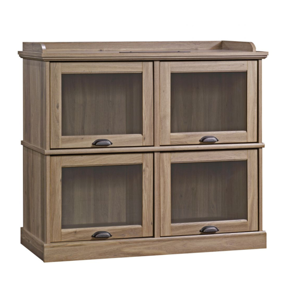
- Page 1 Teknik www.teknikoffice.co.uk Your holder for all things awesome. Barrister Home TV Stand Barrister Home Collection | Model 5414720 NOTE: THIS INSTRUCTION BOOKLET CONTAINS IMPORTANT SAFETY INFORMATION. PLEASE READ AND KEEP FOR FUTURE REFERENCE.
- Page 2 Table of Contents Assembly Tools Required Part Identifi cation No. 2 Phillips Screwdriver Tip Shown Actual Size Hardware Identifi cation Assembly Steps 5-22 Hammer Not actual size Français 23-25 Español 26-28 Skip the power trip. Safety 29-30 This time. Warranty WARNING Use of a TV that is too heavy or large is hazardous.
- Page 3 Now you know Part Identifi cation our ABCs. å While not all parts are labeled, some of the parts will have a label or an inked letter on the edge to help distinguish similar parts from each other. Use this part identifi cation to help identify similar parts. RIGHT END (1) BOTTOM (1) LEFT MOLDING (1)
- Page 4 Hardware Identifi cation å Screws are shown actual size. You may receive extra hardware with your unit. HIDDEN CAM - 16 CAM DOWEL - 12 CAM SCREW - 4 ANGLE BRACKET - 8 MOLDING DOOR HANGER- 8 DOOR STOP - 4 PULL- 4 CONNECTOR - 2 WARNING LABEL - 1...
- Page 5 Step 1 Assemble your unit on a carpeted fl oor or on the empty å carton to avoid scratching your unit or the fl oor. Push sixteen HIDDEN CAMS (1F) into the ENDS (A å and B), LOWER ENDS (C and D), UPRIGHTS (E and F), and BOTTOM (H).
- Page 6 Step 2 Fasten eight DOOR SLIDES (37M) to the ENDS (A and B), å LOWER ENDS (C and D), and UPRIGHTS (E and F). Use twelve BROWN 7/16" LARGE HEAD SCREWS (6S). The large hole will be closest to the fi nished edge of all parts.
- Page 7 Step 3 Fasten the RAILS (R and S) to the TOP (G2). Use seven å BLACK 1-7/8" FLAT HEAD SCREWS (2S). Rounded edge Rounded edge Finished surface r f a w i t l e s BLACK 1-7/8" FLAT HEAD SCREW (7 used in this step) Page 7...
- Page 8 Step 4 Tap two MOLDING CONNECTORS (19F) into the notches å in the MOLDINGS (M, N, and O). Use your hammer to tap the MOLDING CONNECTORS (19F) into the notches in the MOLDINGS. Flat end Flat end Page 8...
- Page 9 Step 5 Fasten the MOLDINGS (M, N, and O) to the TOP (G2). å Use seven SILVER 1-1/8" FLAT HEAD SCREWS (10S). NOTE: Do not over tighten the SCREWS into the TOP. å SILVER 1-1/8" FLAT HEAD SCREW (7 used in this step) Finished surface Page 9...
- Page 10 Step 6 Turn four CAM SCREWS (8F) into the MOLDINGS (N and O). å Page 10...
- Page 11 Step 7 Fasten the ENDS (A and B) to the MOLDINGS (N and O). å Tighten four HIDDEN CAMS. Fasten the UPRIGHT (E) to the TOP (G2). Tighten two å HIDDEN CAMS. Finished edge w i t r f a w i t r f a Finished edge...
- Page 12 Step 8 Fasten the SHELF (I) to the ENDS (A and B) and UPRIGHT (E). å Caution Use six BLACK 1-7/8" FLAT HEAD SCREWS (2S). Do not stand the unit upright without the BACK fastened. The unit may collapse. Rounded edge r f a w i t l e s...
- Page 13 Step 9 Fasten the LOWER ENDS (C and D) and LOWER å UPRIGHT (F) to the SHELF (I). Tighten six HIDDEN CAMS. Maximum Arrow 210 degrees Minimum 190 degrees Finished edge w i t r f a w i t r f a Finished edge w i t...
- Page 14 Step 10 Fasten the BOTTOM (H) to the LOWER ENDS (C and D). å Tighten four HIDDEN CAMS. Maximum Arrow 210 degrees Fasten the BOTTOM (H) to the LOWER UPRIGHT (F). Use å two BLACK 1-7/8" FLAT HEAD SCREWS (2S) Minimum 190 degrees These holes must be here.
- Page 15 Step 11 Fasten eight ANGLE BRACKETS (5G) to the LOWER å ENDS (C and D), BOTTOM (H), and BRACE (K). Use eight BLACK 9/16" LARGE HEAD SCREWS (1S). (8 used) NOTE: Be sure the edges of the ANGLE BRACKETS are å...
- Page 16 Step 12 Carefully turn your unit over onto its front edges. å Fasten the BRACE (K) to the LOWER ENDS (C and D) å and BOTTOM (H). Use four BLACK 9/16" LARGE HEAD SCREWS (1S). BLACK 9/16" LARGE HEAD SCREW (4 used in this step) Page 16...
- Page 17 Step 13 Unfold the BACK (J) and lay it over your unit. å Caution Make equal margins along all two long edges and the two å Do not stand the unit upright without the short edges of the BACK (J). Push on opposite corners of BACK fastened.
- Page 18 Step 14 Fasten the FRONT BASE (P2) to the ENDS (C and D) å and BOTTOM (H). Use four BLACK 9/16" LARGE HEAD SCREWS (1S). Fasten the SIDE BASES (Q) to the LOWER ENDS (C å and D). Use four BROWN 1" FLAT HEAD SCREWS (12S). Unfi...
- Page 19 Step 15 Carefully stand your unit upright. å Push four DOOR STOPS (4I) into the holes in å the UPRIGHTS (E and F). Push the RUBBER SLEEVES (2R) over the METAL PINS (1R). å Insert the METAL PINS into the holes in the ENDS (A, B, C and D) and UPRIGHTS (E and F).
- Page 20 Step 16 Fasten a PULL (70K) to a DOOR (L). Use two GOLD 1" å MACHINE SCREWS (50S). Fasten two DOOR HANGERS (40G) to the DOOR. Use å two BLACK 9/16" LARGE HEAD SCREWS (1S). Repeat this step for the other DOORS. å...
- Page 21 Step 17 Before you begin fastening the remaining DOOR SLIDES (37M), å you must insert the DOOR (L) at an angle placing the DOOR HANGERS behind the large hole on the DOOR SLIDES. Push the door into the unit horizontally. While holding the DOOR, swing the DOOR SLIDE up into place å...
- Page 22 Step 18 Apply the WARNING LABEL (1L) to the TOP (G2). You should be able to read the label when the TV is removed from the å unit. When the TV is in place, it should hide the label. Peel off the backing and apply the label as shown in the diagram. NOTE: This is a permanent label intended to last for the life of the product.
- Page 23 WARNING Please use your furniture correctly and safely. Improper use can cause safety hazards, or damage to your furniture or household items. Carefully read the following safety information. Death or serious injury may occur when children climb on audio and/or video equipment furniture. A remote control or toys placed on the furnishing may encourage a child to climb on the furnishing and as a result may tip over onto the child.
Need help?
Do you have a question about the Barrister 5414720 and is the answer not in the manual?
Questions and answers