
Subscribe to Our Youtube Channel
Related Manuals for Teknik 5414873


Summary of Contents for Teknik 5414873
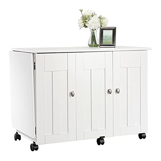
- Page 1 Teknik www.teknikoffice.co.uk Tidy up. Cruise around. Sewing/Craft Cart Model 5414873 NOTE: THIS INSTRUCTION BOOKLET CONTAINS IMPORTANT SAFETY INFORMATION. PLEASE READ AND KEEP FOR FUTURE REFERENCE.
- Page 2 Table of Contents Assembly Tools Required Part Identifi cation No. 2 Phillips Screwdriver Tip Shown Actual Size Hardware Identifi cation Assembly Steps 5-18 Hammer Not actual size Français 19-21 Español 22-25 Skip the power trip. Safety This time. Warranty Page 2...
- Page 3 Now you know Part Identifi cation our ABCs. å While not all parts are labeled, some of the parts will have a label or an inked letter on the edge to help distinguish similar parts from each other. Use this part identifi cation to help identify similar parts. RIGHT END (1) BOTTOM (1) RIGHT DOOR (1)
- Page 4 Hardware Identifi cation å Screws are shown actual size. You may receive extra hardware with your unit. CASTER - 4 17E CASTER BRACKET - 6 LOCKING CASTER - 2 TRAY - 2 TRAY DIVIDER - 8 NON- ADJUSTABLE ADJUSTABLE HINGE - 2 HIDDEN CAM - 14 CAM DOWEL - 14 HINGE - 5...
- Page 5 Step 1 Assemble your unit on a carpeted fl oor or on the empty å carton to avoid scratching your unit or the fl oor. Push fourteen HIDDEN CAMS (1F) into the ENDS (A and B), å UPRIGHT (C2), BOTTOM (F), MODESTY PANEL (G2), and SHELF (H2).
- Page 6 Step 2 Fasten the RIGHT END (A) to the TOP (D). Tighten å Caution two HIDDEN CAMS. Do not stand the unit upright without the Fasten the BOTTOM (F) to the RIGHT END (A). å BACK fastened. The unit may collapse. Tighten two HIDDEN CAMS.
- Page 7 Step 3 Fasten the UPRIGHT (C2) to the TOP (D) and BOTTOM (F). å Tighten four HIDDEN CAMS. Maximum Arrow 210 degrees Fasten the MODESTY PANEL (G2) to the UPRIGHT (C2). Use å two BLACK 1-15/16" FLAT HEAD SCREWS (113S). Minimum Fasten two MAGNETIC CATCHES (5I) to the UPRIGHT (C2).
- Page 8 Step 4 Fasten the LEFT END (B) to the TOP (D) and å MODESTY PANEL (G2). Tighten four HIDDEN CAMS. Maximum Arrow 210 degrees Minimum 190 degrees S u r f a c H I D D E N i t h Page 8...
- Page 9 Step 5 Fasten the SHELF (H2) to the LEFT END (B). Tighten two å HIDDEN CAMS. Maximum Arrow 210 degrees Fasten the SHELF (H2) to the UPRIGHT (C2). Use two å BLACK 1-15/16" FLAT HEAD SCREWS (113S). Minimum 190 degrees Surface with HIDDEN CAMS 113S BLACK 1-15/16"...
- Page 10 Step 6 Carefully turn your unit over onto its front edges. Lay the å Caution BACK (L) over your unit. Do not stand the unit upright without the Make equal margins along all four edges of the BACK (L). å BACK fastened.
- Page 11 Step 7 Fasten two HINGES (16H) to the TOP (D) and å FLIP-UP TOP (E). Use eight BLACK 9/16" LARGE Remember: HEAD SCREWS (1S). Righty tighty. Lefty loosey. BLACK 9/16" LARGE HEAD SCREW (8 used in this step) S u r f a c i t h h o l...
- Page 12 Step 8 Place fi ve CASTER BRACKETS (17E) over the holes in the å bottom edges of ENDS (A and B) and UPRIGHT (C2). Firmly push two LOCKING CASTERS (2CL) into the holes as å shown in the CASTER BRACKETS (17E) and ENDS (A and B). Firmly push three CASTERS (2CN) into the remaining holes å...
- Page 13 Step 9 Fasten a STRIKE PLATE (6I) to the RIGHT DOOR (K). Use å a BLACK 1/2" FLAT HEAD SCREW (11S). Fasten two NON ADJUSTABLE HINGES (2H) to the å RIGHT DOOR (K). Use four BLACK 9/16" LARGE HEAD SCREWS (1S). BLACK 9/16"...
- Page 14 Step 10 Carefully stand your unit upright. å Pro Tip: Lift with your Fasten the RIGHT DOOR (K) to the RIGHT END (A). Use å legs. And, you know, four BLACK 9/16" LARGE HEAD SCREWS (1S). your arms. Fasten a KNOB and BACKPLATE (72K) to the RIGHT å...
- Page 15 Step 11 Fasten the remaining HINGES (16H) to the DOORS (J and MM). Use twelve BLACK 9/16" LARGE HEAD SCREWS (1S). å Fasten the ADJUSTABLE HINGES (3H) to the LEFT DOOR (MM). Use four BLACK 9/16" LARGE HEAD SCREWS (1S). å...
- Page 16 Step 12 Fasten the LEFT DOOR (MM) to the LEFT END (B). Use å four BLACK 9/16" LARGE HEAD SCREWS (1S). Fasten a KNOB and BACKPLATE (72K) to each DOOR (J å and MM). Use two GOLD 1" MACHINE SCREWS (50S). BLACK 9/16"...
- Page 17 Step 13 NOTE: The FLIP-UP TOP (E) can be supported by the å DOORS (J and MM). There are two holes in the bottom surface of the FLIP-UP TOP (E) for the bolt in the SLIDE CATCH (6J) to lock into. Fasten the TRAYS (2D) to the DOORS (J and MM).
- Page 18 Step 14 Push the RUBBER SLEEVES (2R) over the METAL PINS (1R). å Insert the METAL PINS into the hole locations of your choice in If you're doing this to the RIGHT END (A) and UPRIGHT (C2). Set the ADJUSTABLE help a friend, don't SHELVES (I) onto the METAL PINS.
- Page 19 WARNING Please use your furniture correctly and safely. Improper use can cause safety hazards, or damage to your furniture or household items. Carefully read the following chart. Look out for: What can happen: How to avoid the problem: • Overloaded drawers and shelves. •...
Need help?
Do you have a question about the 5414873 and is the answer not in the manual?
Questions and answers