
Subscribe to Our Youtube Channel
Related Manuals for Teknik 5417593


Summary of Contents for Teknik 5417593
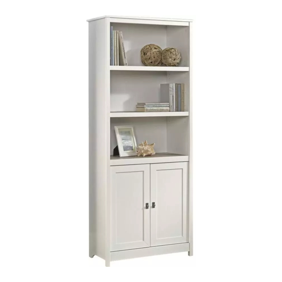
- Page 1 Teknik www.teknikoffice.co.uk Here's one for the books. Shaker Style Bookcase with Doors Model 5417593 NOTE: THIS INSTRUCTION BOOKLET CONTAINS IMPORTANT SAFETY INFORMATION. PLEASE READ AND KEEP FOR FUTURE REFERENCE.
- Page 2 Table of Contents Assembly Tools Required Part Identifi cation No. 2 Phillips Screwdriver Tip Shown Actual Size Hardware Identifi cation Assembly Steps 5-22 Hammer Not actual size Français 23-25 Español 26-28 Skip the power trip. Safety 29-30 This time. Warranty Page 2...
- Page 3 Now you know Part Identifi cation our ABCs. å While not all parts are labeled, some of the parts will have a label or an inked letter on the edge to help distinguish similar parts from each other. Use this part identifi cation to help identify similar parts. RIGHT END (1) LEFT END (1) C2 TOP (1)
- Page 4 Hardware Identifi cation å Screws are shown actual size. You may receive extra hardware with your unit. HIDDEN CAM - 20 CAM DOWEL - 12 CAM SCREW - 8 METAL BRACKET - 8 14H HINGE - 4 100K KNOB SET - 2 DOOR STOP - 2 NAIL - 60 METAL PIN - 12...
- Page 5 Step 1 Assemble your unit on a carpeted fl oor or on the empty å carton to avoid scratching your unit or the fl oor. Scan this QR code to watch a video on how to assemble your unit. Push twelve HIDDEN CAMS (1F) into the ENDS (A and B), å...
- Page 6 Step 2 Push eight HIDDEN CAMS (1F) into the remaining holes of å the ENDS (A and B). Some assembly (and snacks) required. Arrow (8 used) Arrow The arrow in the HIDDEN CAM must point toward the hole in the edge of the board. Arrow Hole Page 6...
- Page 7 Step Step 3 Turn eight CAM SCREWS (8F) into the LEGS (J and K). å (8 used) Page 7...
- Page 8 Step Step 4 Fasten the LEGS (J and K) to the ENDS (A and B). Tighten å eight HIDDEN CAMS. Edge with CAM DOWELS i t h f a c S u r These surfaces D E N should be even. H I D Edge with CAM DOWELS...
- Page 9 Step Step 5 Fasten the SHELF (E) to the LEFT END (B). Tighten two å Caution HIDDEN CAMS. Do not stand the unit upright without the Slide the SHELF MOLDING (N) onto the notched edge of å BACK fastened. The unit may collapse. the SHELF (E).
- Page 10 Step 6 Fasten the BOTTOM (D) to the LEFT END (B). Tighten two å HIDDEN CAMS. Maximum Arrow 210 degrees Fasten the RIGHT END (A) to the BOTTOM (D) and å SHELF (E). Tighten four HIDDEN CAMS. Minimum 190 degrees These holes must be here.
- Page 11 Step 7 Fasten the TOP (C2) to the ENDS (A and B). Tighten four å HIDDEN CAMS. Maximum Arrow 210 degrees Minimum 190 degrees These holes must be here. S u r f a c i t h h o l Page 11...
- Page 12 Step 8 Fasten three METAL BRACKETS (4G) to the TOP MOLDING (M). å Use three BLACK 9/16" LARGE HEAD SCREWS (1S). Don't worry. It isn't Rome. This can be built NOTE: Be sure the BRACKETS are even with the edges of the å...
- Page 13 Step 9 Fasten the TOP MOLDING (M) to the TOP (C2). Use three å BLACK 9/16" LARGE HEAD SCREWS (1S) through the METAL BRACKETS on the TOP MOLDING and into the TOP. BLACK 9/16" LARGE HEAD SCREW (3 used in this step) Page 13...
- Page 14 Step 10 Fasten the SPACER (P) to the SHELF (E). Use two å BROWN 1-1/2" FLAT HEAD SCREWS (14S). Then, insert two DOOR STOPS (4I) into the center holes å in the SPACER (P). BROWN 1-1/2" FLAT HEAD SCREW (2 used in this step) These holes are closer to this edge.
- Page 15 Step 11 Carefully turn your unit over onto its front edges. å Fasten fi ve METAL BRACKETS (4G) to the ENDS (A and B) and å BOTTOM (D). Use fi ve BLACK 9/16" LARGE HEAD SCREWS (1S). NOTE: Be sure the BRACKETS are even with the edges of å...
- Page 16 Step 12 Unfold the BACK (F) and lay it over your unit. å Caution Make equal margins along all four edges of the BACK (F). å Do not stand the unit upright without the Push on opposite corners of your unit if needed to make BACK fastened.
- Page 17 Step 13 Fasten four HINGES (14H) to the DOORS (G). Use eight å BLACK 1/2" FLAT HEAD SCREWS (11S). BLACK 1/2" FLAT HEAD SCREW (8 used in this step) Page 17...
- Page 18 Step 14 Carefully stand your unit upright. å Pro Tip: Lift with your Before fastening the DOOR to your unit, be sure the å legs. And, you know, mounting screw is against the stops as shown in the right your arms. diagram.
- Page 19 Step 15 Refer to the enlarged diagram to identify the parts on å the HINGES. The DOORS may need some adjustments. Follow the text below å to make needed adjustments. DOOR ADJUSTMENTS: å To adjust the DOORS from side to side (horizontal), turn the adjusting screw in or out.
- Page 20 Step 16 Slide an ADJUSTABLE SHELF MOLDING* (O) onto the notched å edge of an ADJUSTABLE SHELF (H). Repeat this step for the other ADJUSTABLE SHELF (H). å *U.S. Patent No. 5,499,886 å Notched edge Slide the ADJUSTABLE SHELF MOLDING (O) onto the notched edge. These surfaces should be even.
- Page 21 Step 17 Open the FURNITURE TIPPING RESTRAINT KIT (97) and å fasten the SAFETY STRAP to the TOP (C2). Use the provided BLACK 9/16" LARGE HEAD SCREW. NOTE: Position the SAFETY STRAP exactly as shown. å Push the RUBBER SLEEVES (2R) over the METAL å...
- Page 22 Step 18 IMPORTANT: The unit must be placed against a wall. å å NOTE: Do not turn the SAFETY DRYWALL ANCHOR into a wall stud. If you prefer to fasten the SAFETY STRAP to a wall stud, go to your local hardware store for proper hardware. å...
- Page 23 WARNING Please use your furniture correctly and safely. Improper use can cause safety hazards, or damage to your furniture or household items. Carefully read the following chart. Look out for: What can happen: How to avoid the problem: • Overloaded shelves. •...
Need help?
Do you have a question about the 5417593 and is the answer not in the manual?
Questions and answers