
Related Manuals for Teknik 5418793


Summary of Contents for Teknik 5418793
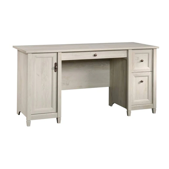
- Page 1 Teknik www.teknikoffice.co.uk For all your newfangled gadgetry. ChalkedWood Computer Desk Model 5418793 NOTE: THIS INSTRUCTION BOOKLET CONTAINS IMPORTANT SAFETY INFORMATION. PLEASE READ AND KEEP FOR FUTURE REFERENCE.
- Page 2 Table of Contents Assembly Tools Required Part Identifi cation No. 2 Phillips Screwdriver Tip Shown Actual Size Hardware Identifi cation Assembly Steps 6-29 Hammer Not actual size Skip the power trip. This time. Part Identifi cation å While not all parts are labeled, some of the parts will have a label or an inked letter on the edge to help distinguish similar parts from each other.
- Page 3 Now you know Part Identifi cation our ABCs. D341 D102 D930 D341 D102 D340 D214 D930 D340 D214 Page 3...
- Page 4 Hardware Identifi cation å Screws are shown actual size. You may receive extra hardware with your unit. BLACK RIGHT BLACK LEFT BLACK RIGHT BLACK LEFT CABINET RAIL - 1 CABINET RAIL - 1 DRAWER SLIDE - 1 DRAWER SLIDE - 1 40CA CABINET RIGHT - 2 40CB CABINET LEFT - 2 40CC DRAWER RIGHT - 2...
-
Page 5: Table Of Contents
Hardware Identifi cation å Screws are shown actual size. You may receive extra hardware with your unit. BLACK 9/16" LARGE HEAD SCREW - 9 BLACK 1-7/8" FLAT HEAD SCREW - 4 GOLD 5/16" FLAT HEAD SCREW - 20 BLACK 1-1/4" FLAT HEAD SCREW -16 BLACK 1/2"... - Page 6 Step 1 Assemble your unit on a carpeted fl oor or on the empty å carton to avoid scratching your unit or the fl oor. To begin assembly, push two SAUDER TWIST-LOCK® å FASTENERS (12F) into the large holes in the MODESTY PANEL (H).
- Page 7 Step 2 Push thirty-two HIDDEN CAMS (1F) into the ENDS (A and B), å UPRIGHTS (C and D), BOTTOMS (F and G), and KEYBOARD BRACES (J). Then, insert a CAM DOWEL (2F) into each HIDDEN CAM, except for the CAMS in the long edges of the ENDS and UPRIGHTS.
- Page 8 Step 3 Fasten the CABINET RIGHTS (40CA) and CABINET å LEFTS (40CB) to the RIGHT END (A) and RIGHT Remember: UPRIGHT (C). Use eight GOLD 5/16" FLAT HEAD Righty tighty. SCREWS (3S) through holes #1 and #3. Lefty loosey. GOLD 5/16" FLAT HEAD SCREW (8 used in this step) Roller end Edge with...
- Page 9 Step 4 Fasten the BLACK CABINET RAILS (AA and BB) to the å KEYBOARD BRACES (J). Use four GOLD 5/16" FLAT HEAD SCREWS (3S). NOTE: The CABINET RAILS are marked "CABINET å RIGHT" and "CABINET LEFT" for easy identifi cation. Roller end GOLD 5/16"...
- Page 10 Step 5 Turn twelve CAM SCREWS (8F) into the LEGS (M2). å Remember: Righty tighty. Lefty loosey. (12 used) Page 10...
- Page 11 Step 6 Fasten the LEGS (M2) to the ENDS (A and B) and å UPRIGHTS (C and D). Tighten twelve HIDDEN CAMS. These surfaces should be even. These surfaces should be even. These surfaces should be even. These surfaces should be even. Page 11...
- Page 12 Step 7 Fasten a FOOT (X) to each LEG (M2). Use four BLACK å BLACK 1-9/16" FLAT HEAD SCREWS (30S). BLACK 1-9/16" FLAT HEAD SCREW (4 used in this step) Page 12...
- Page 13 Step 8 Fasten the MODESTY PANEL (H) to the TOP (E). Tighten å Caution two TWIST-LOCK® FASTENERS. Do not stand the unit upright without the BACK fastened. The unit may collapse. How to use the SAUDER TWIST-LOCK ® FASTENER 1. Insert the dowel end of the FASTENER into the hole of the adjoining part.
- Page 14 Step 9 Fasten the KEYBOARD BRACES (J) to the TOP (E). å Tighten four HIDDEN CAMS. Rounded edge Roller end Caution Start Tighten Risk of damage or Arrow injury. HIDDEN CAMS must be completely Arrow Maximum tightened. HIDDEN 210 degrees CAMS that are not completely tightened may loosen, and parts...
- Page 15 Step 10 Fasten the UPRIGHTS (C and D) to the TOP (E). Tighten four å HIDDEN CAMS. Maximum Arrow 210 degrees Fasten the UPRIGHTS (C and D) to the MODESTY PANEL (H). å Use four BLACK 1-7/8" FLAT HEAD SCREWS (2S). Minimum 190 degrees BLACK 1-7/8"...
- Page 16 Step 11 Insert four METAL PINS (1R) into the RIGHT BOTTOMS (F). å Maximum Arrow Fasten the BOTTOMS (F and G) to the UPRIGHTS (C and D). å 210 degrees Tighten four HIDDEN CAMS. NOTE: Be sure the METAL PINS in the RIGHT BOTTOMS å...
- Page 17 Step 12 Fasten the ENDS (A and B) to the BOTTOMS (F and G) å and TOP (E). Tighten eight HIDDEN CAMS. Maximum Arrow 210 degrees NOTE: Be sure the METAL PINS in the RIGHT BOTTOMS å insert into the holes in the RIGHT END. Minimum 190 degrees Page 17...
-
Page 18: Black 9/16" Large Head Screw
Step 13 Fasten four ANGLE BRACKETS (44G) to the BOTTOMS (F and å G). Use four BLACK 9/16" LARGE HEAD SCREW (1S). NOTE: Be sure the edges of the ANGLE BRACKETS are even å with the edge of the BOTTOMS. Fasten the BOTTOM MOLDINGS (W) to the ANGLE BRACKETS. - Page 19 Step 14 Carefully turn your unit over onto its front edges. Place the å Caution BACKS (I) over the ENDS and UPRIGHTS. Do not stand the unit upright without the Make equal margins along the sides of the BACKS (I). å...
-
Page 20: Black 1/2" Flat Head Screw
Step 15 Fasten two HINGES (14H) to the DOOR (K). Use four å BLACK 1/2" FLAT HEAD SCREWS (11S). BLACK 1/2" FLAT HEAD SCREW (4 used in this step) Page 20... - Page 21 Step 16 Carefully stand your unit upright. å Pro Tip: Lift with your Before fastening the DOOR to your unit, be sure the å legs. And, you know, mounting screw is against the stops as shown in the right your arms. diagram.
- Page 22 Step 17 Refer to the enlarged diagram to identify the parts on the HINGES and å HINGE BRACKETS. The DOOR may need some adjustments. Follow the text below to å make needed adjustments. DOOR ADJUSTMENTS: å To adjust the DOOR from side to side (horizontal), turn the adjusting å...
- Page 23 Step 18 Fasten the KEYBOARD HINGES (12H) to the KEYBOARD FRONT (N). å Use four SILVER 5/8" FLAT HEAD SCREWS (23S). Fasten the KEYBOARD HINGES (12H) to the KEYBOARD SHELF (O). å Use two SILVER 9/16" LARGE HEAD SCREWS (54S). SILVER 5/8"...
-
Page 24: Brown 1" Flat Head Screw
Step 19 Fasten the BLACK DRAWER SLIDES (CC and DD) to the å KEYBOARD SHELF (O). Use four BROWN 1" FLAT HEAD SCREWS (18S). NOTE: The DRAWER SLIDES are marked "DRAWER å RIGHT" and "DRAWER LEFT" for easy identifi cation. Turn the CORD CLIP (4P) into the KEYBOARD SHELF (O). -
Page 25: Black 1-1/4" Flat Head Screw -16
Step 20 Fasten the LARGE DRAWER SIDES (D102) to one of the å LARGE DRAWER BOX FRONTS (D341). Use four BLACK 1-1/4" FLAT HEAD SCREWS (7S). Slide the DRAWER BOTTOM (D930) into the grooves in the å DRAWER SIDES (D102). Fasten the remaining LARGE DRAWER BOX FRONT (D341) å... -
Page 26: Black 7/8" Large Head Screw
Step 21 Fasten the LARGE DRAWER FRONT (P) to a LARGE å DRAWER BOX FRONT (D341). Use four BLACK 7/8" LARGE HEAD SCREWS (17S). Fasten a KNOB (124K) to the LARGE DRAWER FRONT (P). å Use a BLACK 1-1/8" MACHINE SCREW (21S) through the LARGE DRAWER BOX FRONT, through the LARGE DRAWER FRONT, and into the KNOB. - Page 27 Step 22 Fasten the DRAWER RIGHT (40CC) and DRAWER å LEFT (40CD) to the LARGE DRAWER SIDES (D102). Use four GOLD 5/16" FLAT HEAD SCREWS (3S) through holes #2 and #4. Repeat this step for the small drawer. å Roller end D102 Roller end D102...
- Page 28 Step 23 Push a FILE GLIDE (3B) onto the RIGHT DRAWER SIDE (D102). å Slide the FILE RODS (7B) into the FILE GLIDE (3B) on the å RIGHT DRAWER SIDE. Slide another FILE GLIDE (3B) onto the other end of the FILE å...
- Page 29 Step 24 Push the RUBBER SLEEVES (2R) over the METAL PINS (1R). Insert the METAL PINS into the hole locations of your choice å in the LEFT END (B) and LEFT UPRIGHT (D). Set the ADJUSTABLE SHELF (L) onto the METAL PINS. Push a CAM COVER (33P) onto each HIDDEN CAM.
- Page 30 WARNING Please use your furniture correctly and safely. Improper use can cause safety hazards, or damage to your furniture or household items. Carefully read the following chart. Look out for: What can happen: How to avoid the problem: • Overloaded shelves and drawers. •...
Need help?
Do you have a question about the 5418793 and is the answer not in the manual?
Questions and answers