Table of Contents
Advertisement
Advertisement
Table of Contents

Related Manuals for THORLABS KBD101


Summary of Contents for THORLABS KBD101
- Page 1 KBD101 K-Cube Brushless DC Servo Driver User Guide Original Instructions...
-
Page 2: Table Of Contents
Contents Chapter 1 Safety ..................... 4 1.1 Safety Information .................. 4 1.2 General Warnings .................. 4 Chapter 2 Overview and Setup ..............5 2.1 Introduction ..................... 5 2.2 PC Software Overview ................7 2.2.1 Introduction ......................7 2.2.2 Kinesis Server ....................7 2.2.3 Software Upgrades ..................... - Page 3 6.3.7 Triggering Latency ................... 58 6.3.8 Rotation StagesTab ..................59 Appendices Appendix A Rear Panel Connector Pinout Details ........60 Appendix B Preventive Maintenance ............61 Appendix C Specifications ................62 Appendix D Regulatory ................63 Appendix E Thorlabs Worldwide Contacts ..........66...
-
Page 4: Chapter 1 Safety
To minimize the possibility of this happening it is strongly recommended that any such modes that result in prolonged unresponsiveness be disabled before the software is run. Please consult your system administrator or contact Thorlabs technical support for more details. -
Page 5: Chapter 2 Overview And Setup
Chapter 2 Overview and Setup 2.1 Introduction The KBD101 Brushless DC Motor K-Cubes are ideal for motion control applications demanding high speed (100s of mm/s) and high encoder resolution (<100 nm) operation. These single channel drivers offer high-precision motion control in a wide range of applications, and in particular when used along with our DDSM100 fast translation stage where speeds of up to 500 mm/sec can be achieved. - Page 6 For power, a single way wall plug supply (KPS101) is also available for powering a single K-Cube Driver. As a further level of convenience when using the new K-Cube Controllers Thorlabs also offers the 3-channel and 6-channel K-Cube Controller Hubs (KCH301 and KCH601).
-
Page 7: Pc Software Overview
Brushless DC Servo Driver K-Cube 2.3 PC Software Overview 2.3.1 Introduction The K-Cube range of controllers share many benefits. These include USB connectivity (allowing multiple units to be used together on a single PC), fully featured Graphical User Interface (GUI) panels, and extensive software function libraries for custom application development. - Page 8 Chapter 2 Consider the control supplied for the KBD101 Brushless DC Servo driver unit. This Control provides a complete user graphical instrument panel to allow the motor unit to be manually operated, as well as a complete set of software functions (often called methods) to allow all parameters to be set and motor operations to be automated by a client application.
-
Page 9: Software Upgrades
Kinesis Controls collection. This is available either by pressing the F1 key when running the Kinesis server, or via the Start menu, Start\Programs\Thorlabs\Kinesis\Kinesis Help. 2.3.3 Software Upgrades Thorlabs operate a policy of continuous product development and may issue software upgrades as necessary. -
Page 10: Chapter 3 Getting Started
To minimize the possibility of this happening it is strongly recommended that any such modes that result in prolonged unresponsiveness be disabled before the software is run. Please consult your system administrator or contact Thorlabs technical support for more details. Caution Some PCs may have been configured to restrict the users ability to load software, and on these systems the software may not install/run. -
Page 11: Mechanical Installation
(KCH301 and KCH601). ) are also available - see Section 2.2. for further details. Full instructions on the fitting and use of the controller hub are contained in the handbook available at www.thorlabs.com Caution When siting the unit, it should be positioned so as not to impede the operation of the control panel buttons. -
Page 12: Using The Baseplate
Chapter 3 3.2.3 Using the Baseplate The baseplate must be bolted to the worksurface before the K-Cube is fitted, as shown below. The K-cube is then located on two dowels in the baseplate and secured by two clips. Fig. 3.1 Using The Baseplate 3.3 Electrical Installation 3.3.1 Rear Panel Fig. -
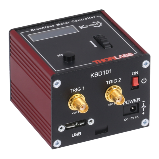
Page 13: Front Panel
DC power supply of 15 V, 2A. Thorlabs offers a compact, multi-way power supply unit (TPS008), allowing up to four KBD101 K-Cubes to be powered from a single mains outlet. A single way wall plug supply (KPS101) for powering a single Driver K-Cube is also available. -
Page 14: Connect The Hardware
Chapter 3 3.4 Connect The Hardware 1) Perform the mechanical installation as detailed in Section 3.2. 2) Install the Kinesis Software. Caution During items (3) to (6) the instructions should be followed strictly in the order stated. Problems may occur if the process is not performed in the correct sequence. - Page 15 Brushless DC Servo Driver K-Cube The unit takes about 5 seconds from power application until warm up is finished, and phase initialization is complete. During this time the following screens are displayed. T h o r l a b s K B D 1 0 1 S w R e v 1 0 0 0 2 S t a g e c o n n e c t e d : D D S M 1 0 0...
-
Page 16: Stage Selection
Kinesis server applies automatically, suitable default parameter values on boot up of the software. For Thorlabs stages, the association is performed automatically when the stage is connected and suitable default parameter values are loaded when the controller is first powered up. -
Page 17: Chapter 4 Standalone Operation
4.1 Introduction The Brushless DC Driver K-Cube has been designed specifically to operate with the range of Thorlabs Brushless DC motorised opto-mechanical products. The unit offers a fully featured motion control capability including velocity profile settings, limit switch handling, homing sequences and, for more advanced operation, adjustment of PID settings, allowing support for many different actuator configurations. -
Page 18: Digital Display - Operating Mode
Chapter 4 4.2.1 Digital Display - Operating Mode During normal operation, the digital display shows the current position (in millimeters or degrees) and the current state of the motor (Stopped or Moving). If the stage being driven has been homed, the display will also show ‘Homed’. Brushless Motor Controller A t 0 . -
Page 19: Velocity Wheel Operation
Brushless DC Servo Driver K-Cube This mode of operation is enabled by setting the ‘Wheel Mode’ to ‘Go To Position’ through the software GUI - see Section 6.3.4. or via the display menu, see Section 4.4.6. Note for Rotation Stage Users If the current absolute position is outside the 0 to 360 degree range, then "go to position"... -
Page 20: Settings Menu
Chapter 4 4.4 Settings Menu 4.4.1 Overview A t 0 . 0 0 0 0 m m S t o p p e d Press the MENU button MENU Use the wheel to scroll through the menu options M e n u o p t i o n s U s e w h e e l Press the MENU button to enter a particular option M e n u o p t i o n s... -
Page 21: Menu Option - Enable/Disable
4.4.2 Menu Option - Enable/Disable After initial start up the drive channel is disabled, and A t 0 . 0 0 0 0 m m D i s a b l e d must be enabled before the stage can be driven. MENU Press the MENU button, then use the wheel to scroll M e n u o p t i o n s... -
Page 22: Menu Option - Go To Position
Chapter 4 4.4.3 Menu Option - Go to position A t 0 . 0 0 0 0 m m This mode is used to move to an absolute position. S t o p p e d MENU Press the MENU button, then use the wheel to scroll through the menu options. -
Page 23: Menu Option - Start Homing
Brushless DC Servo Driver K-Cube 4.4.4 Menu Option - Start homing A t 2 . 0 0 0 0 m m This mode is used to home the stage. S t o p p e d MENU Press the MENU button, then use the wheel to scroll through the menu options. -
Page 24: Menu Option - Joystick Mode
Chapter 4 4.4.6 Menu Option - Joystick Mode A t 0 . 0 0 0 0 m m This mode is used to set the operating mode of the H o m e d S t o p p e d V joystick wheel. -
Page 25: Menu Option - Jog Step Size
Brushless DC Servo Driver K-Cube 4.4.7 Menu Option - Jog Step Size A t 0 . 0 0 0 0 m m This mode is used to set the jog step size. H o m e d S t o p p e d V MENU Press the MENU button, then use the wheel to scroll through the menu options. -
Page 26: Menu Option - Teach Position
Chapter 4 4.4.8 Menu Option - Teach Position This mode is used to set the teach positions, used when the Joystick mode option is set to Jog to positions mode - see Section 4.4.6. To set Teach Position 1... A t 1 0 . 0 0 0 0 m m Move the stage to the position to use as teach position 1. -
Page 27: Menu Option - Brightness
4.4.9 Menu Option - Brightness A t 0 . 0 0 0 0 m m In certain applications, it may be necessary to adjust the H o m e d S t o p p e d V brightness of the LED display. The brightness is set as a MENU value from 0 (Off) to 100 (brightest). -
Page 28: External Triggering
Chapter 4 4.5 External Triggering External triggering is facilitated by the ‘TRIG 1’ and ‘TRIG 2 connectors on the front panel of the unit - see Section 3.3.2.. These connectors are controlled via the Kinesis software (see Section 6.3.5.) and provide a 5V logic level input/output that can be configured to support triggering from and to external devices. -
Page 29: Trigger Out
Brushless DC Servo Driver K-Cube 4.5.3 Trigger Out CMOS Logic Gate 470R Connector Protection Fig. 4.4 TRIG OUT Connection Detail The TRIG output is the output of a standard 5V CMOS logic gate in series with a 470Ω resistor. The resistor provides protection against accidentally short circuiting to ground by limiting the current to approx 10 mA maximum. -
Page 30: Chapter 5 Tutorial
However, if the output is disabled (with the driver connected and monitoring the position) and the stage is moved manually at high speeds, it is possible to exceed this limit. If the KBD101 driver is subsequently used again to move the stage, the incorrect encoder reading will cause incorrect operation, often resulting in sudden uncontrolled moves. -
Page 31: Using The Kinesis Software
The Software should be installed (Section 3.1.) and the power up procedure performed (Section 3.3.) before software operation can be verified. 1) Run the Kinesis software - Start/All Programs/Thorlabs/Kinesis/Kinesis. 1) Notice how the DDSM100 stage type, selected at start up, is displayed in the window. -
Page 32: Homing Motors
Chapter 5 5.4 Homing Motors The need for homing comes from the fact that on power up the motor (stage) is at a random position, so the value of the position counter is meaningless. Homing involves moving the motor to a known reference marker and resetting the position counter to the associated absolute value. -
Page 33: Changing Motor Parameters And Moving To An Absolute Position
Brushless DC Servo Driver K-Cube 5.5 Changing Motor Parameters and Moving to an Absolute Position Absolute moves are measured in real world units (e.g. millimetres), relative to the Home position. Moves are performed using a trapezoidal velocity profile (see Section 6.3.5.). The velocity settings relate to the maximum velocities at which a move is performed, and the acceleration at which the motor speeds up from zero to maximum velocity. -
Page 34: Jogging
Chapter 5 5.6 Jogging During PC operation, the motor actuators are jogged using the GUI panel arrow keys. There are two jogging modes available, ‘Single Step’ and ‘Continuous’. In ‘Single Step’ mode, the motor moves by the step size specified in the Step Distance parameter. -
Page 35: Setting Move Sequences
Brushless DC Servo Driver K-Cube 5.7 Setting Move Sequences The Kinesis software allows move sequences to be programmed, allowing several positions to be visited without user intervention. For more details and instructions on setting move sequences, please see the Kinesis Helpfile. 5.8 Changing and Saving Parameter Settings During operation, certain settings (e.g. -
Page 36: Chapter 6 Software Reference
Chapter 6 Software Reference 6.1 Introduction This chapter gives an explanation of the parameters and settings accessed from the Kinesis software running on a PC. 6.2 GUI Panel The following screen shot shows the graphical user interface (GUI) displayed when accessing the Brushless DC driver using the Kinesis software. - Page 37 Brushless DC Servo Driver K-Cube These settings can be adjusted as described previously, or by clicking the Settings button to display the settings window, see Section 6.3.2. Jog Controls - used to increment or decrement the motor position. The controls comprise a bar graph and a set of jog arrows.
-
Page 38: Keyboard Shortcuts
Chapter 6 Stop - halts the movement of the motor. Lower Display - Shows the present state of the motor, e.g. Idle, Moving, Moving EXT or Homing. Also shows the part number of the associated actuator or stage. 6.2.1 Keyboard Shortcuts Certain functionality can also be accessed via PC keyboard shortcuts as follows: Jog Forwards ‘Ctrl’... -
Page 39: Settings Panel
Brushless DC Servo Driver K-Cube 6.3 Settings Panel When the 'Settings' button on the GUI panel is clicked, the 'Settings' window is displayed. This panel allows motor operation parameters such as move/jog velocities, and stage/axis information to be modified. There are two settings tabs, ‘Current Device Setting’ and Device Startup Settings’. The Current Device settings option shows the settings currently active in the device. -
Page 40: Moves/Jogs Tab
Chapter 6 6.3.2 Moves/Jogs tab Fig. 6.2 Move/Jog Settings Display Units By default, the unit will display position in real world units (mm or degrees). If required, the units can be changed to so that the display shows other positional units (cm, µm, µrad etc). - Page 41 Brushless DC Servo Driver K-Cube Jog Parameters Note Under certain velocity parameter and move distance conditions, the maximum velocity may never be reached (i.e. the move comprises an acceleration and deceleration phase only). The limits for the max velocity or acceleration parameters are dependent on the stage being driven.
- Page 42 Chapter 6 Immediate - the motor stops quickly, in a non-profiled manner Profiled - the motor stops in a profiled manner using the jog Velocity Profile parameters set above. Maximum Velocity - the maximum velocity at which to perform a move. Note Under certain velocity parameter and move distance conditions, the maximum velocity may never be reached (i.e.
-
Page 43: Stage/Axis Tab
They need to be set accordingly such that a particular stage is driven properly by the system. For Thorlabs stages, the Kinesis server will automatically apply suitable defaults for the parameters on this tab during boot up of the software. - Page 44 Chapter 6 Stage Axis Settings These parameters are read automatically when the actuator/stage was associated at start up - see Section 3.5. These settings are provided for information only and cannot be adjusted. They should always be quoted when requesting technical support. Actuator Name - The name (part number) of the stage or actuator connected.
-
Page 45: Advanced Settingstab
Brushless DC Servo Driver K-Cube Hardware Limit Switches Note The minimum velocity and acceleration/deceleration parameters for a home move are taken from the existing move velocity profile parameters. The operation of the limit switches is inherent in the design of the associated stage or actuator. - Page 46 Chapter 6 Position Loop Settings The motion processors within the KBD101 driver uses a position control loop to determine the motor command output. The purpose of the position loop is to match the actual motor position and the demanded position. This is achieved by comparing the demanded position with the actual encoder position to create a position error, which is then passed through a digital PID-type filter.
- Page 47 Brushless DC Servo Driver K-Cube Derivative Recalculation Time – Time over which derivative is calculated. Under normal circumstances, the derivative term of the PID loop is recalculated at every servo cycle. However, it may be desirable to increase the sampling rate to a higher value, in order to increase stability.
- Page 48 Chapter 6 Current Loop Settings The motion processor within the TBD driver uses digital current control as a technique to control the current through each phase winding of the motors. In this way, response times are improved and motor efficiency is increased. This is achieved by comparing the required current with the actual current to create a current error, which is then passed through a digital PI-type filter.
- Page 49 Brushless DC Servo Driver K-Cube Current Loop Settings (Settled) The following parameters are designed to assist in maintaining stable operation and redusing noise at the demanded position. They allow the system to be tuned such that errors caused by external vibration and manual handling (e.g. loading of samples) are minimized, and are applicable only when the stage is settled, i.e.
- Page 50 Chapter 6 set default maximum, in the range 0% to 100%. When the accumulated energy exceeds the value specified in the Energy Limit parameter, a 'current foldback' condition is said to exist, and the commanded current is limited to the value specified in the Current Limit parameter.
-
Page 51: Advanced - Misc. Tab
Brushless DC Servo Driver K-Cube programmable position error limit within which the axis must remain, but unlike the Position Error Limit parameter set in the Position Loop Settings group, the axis is not stopped if it moves outside the specified tracking window. This function is useful for processes that rely on the motor's correct tracking of a set trajectory within a specific range. - Page 52 Chapter 6 deflection is increased. Bidirectional control of motor moves is possible by moving the wheel in both directions. Joystick Mode Velocity Control - Deflecting the wheel starts a move with the velocity proportional to the deflection. The maximum velocity (i.e. velocity corresponding to the full deflection of the joystick wheel) and acceleration are set in the Max Velocity and Acceleration.
- Page 53 Brushless DC Servo Driver K-Cube Velocity Profile Settings To prevent the motor from stalling, it must be ramped up gradually to its maximum velocity. Certain limits to velocity and acceleration result from the torque and speed limits of the motor, and the inertia and friction of the parts it drives. The system incorporates a trajectory generator, which performs calculations to determine the instantaneous position, velocity and acceleration of each axis at any given moment.
- Page 54 Chapter 6 In this profile mode, the acceleration increases gradually from 0 to the specified acceleration value, then decreases at the same rate until it reaches 0 again at the specified velocity. The same sequence in reverse brings the axis to a stop at the programmed destination position.
-
Page 55: Triggering
Brushless DC Servo Driver K-Cube 6.3.6 Triggering Fig. 6.9 Triggering Tab Triggering Introduction The K-Cube motor controllers have two bidirectional trigger ports (TRIG1 and TRIG2) that can be used to read an external logic signal or output a logic level to control external equipment. - Page 56 Chapter 6 Input Trigger Modes When configured as an input, the TRIG ports can be used as a general purpose digital input, or for triggering a relative, absolute or home move. When used for triggering a move, the port is edge sensitive. In other words, it has to see a transition from the inactive to the active logic state (Low->High or High->Low) for the trigger input to be recognized.
- Page 57 Brushless DC Servo Driver K-Cube Trigger Out Position Steps Note If the trigger mode is not set to one of the three position modes described previously, then the following parameters are not applicable and will be hidden. As soon as a position triggering mode is selected on either of the TRIG ports, the port will assert the inactive logic state, set in the Trigger Polarity parameters.
- Page 58 Chapter 6 parameter. This means that the total number of pulses output will be Trigger Cycle Counts x (Forward Trigger Count + Reverse Trigger Count).. PosIntervalFwd 15 mm Pos2 Fwd 12 mm Pos1 Rev StartPosRev 10 mm StartPosFwd Pos1 Fwd Time Trig Voltage Time...
-
Page 59: Triggering Latency
Brushless DC Servo Driver K-Cube 6.3.7 Triggering Latency The detection of whether a trigger condition has occurred is carried out periodically at 102 µs intervals. As a result, there is a maximum 102 µs delay between the condition occurring and the trigger output being updated. The following timing diagram illustrates this latency: Trigger condition occurs time... -
Page 60: Rotation Stagestab
Chapter 6 6.3.8 Rotation StagesTab Rotation Mode This setting relates to the way in which the angular position is displayed on the GUI panel. There are three options: Fixed Range - The angular rotation is limited to 360° i.e. one revolution. Equivalent Angle –... -
Page 61: Appendix A Rear Panel Connector Pinout Details
Quadrature X+/-: Differential quadrature pulses of the encoder Encoder Index I -/+: The differential Index pulse used for homing Limit -/+: Positive and negative limit switch signals Stage ID: Unique Thorlabs communication interface signal used to identify the stage connected. Fig. A.1... -
Page 62: Appendix B Preventive Maintenance
The equipment contains no user servicable parts. There is a risk of electrical shock if the equipment is operated with the covers removed. Only personnel authorized by Thorlabs Ltd and trained in the maintenance of this equipment should remove its covers or attempt any repairs or adjustments. -
Page 63: Appendix C Specifications
Appendix C Specifications C.1 Specifications Parameter Value Drive Connector 15-Pin D-Type, Female (Motor Phase Outputs, Stage ID Input) Peak Current Output PWM Frequency 40 kHz Operating Modes Position, Velocity Control Algorithm 16-bit Digital PID Servo Loop with Velocity and Acceleration Feedforward Velocity Profile Trapezoidal/S-Curve Position Count... -
Page 64: Appendix D Regulatory
Appendix D Regulatory D.1 Declarations Of Conformity D.1.1 For Customers in Europe See Section D.3. D.1.2 For Customers In The USA This equipment has been tested and found to comply with the limits for a Class A digital device, persuant to part 15 of the FCC rules. These limits are designed to provide reasonable protection against harmful interference when the equipment is operated in a commercial environment. - Page 65 • left over parts of units disassembled by the user (PCB's, housings etc.). If you wish to return a unit for waste recovery, please contact Thorlabs or your nearest dealer for further information. D.2.2 Waste treatment on your own responsibility If you do not return an "end of life"...
- Page 66 Appendix D D.3 CE Certificate HA0364T Rev Ck Jan 2017...
-
Page 67: Appendix E Thorlabs Worldwide Contacts
Brushless DC Servo Driver K-Cube Appendix E Thorlabs Worldwide Contacts For technical support or sales inquiries, please visit us at www.thorlabs.com/contact for our most up-to-date contact information. USA, Canada, and South America UK and Ireland Thorlabs, Inc. Thorlabs Ltd. sales@thorlabs.com sales.uk@thorlabs.com... - Page 68 www.thorlabs.com...
Need help?
Do you have a question about the KBD101 and is the answer not in the manual?
Questions and answers