Table of Contents
Advertisement
Quick Links
Advertisement
Table of Contents

Related Manuals for THORLABS TDC001


Summary of Contents for THORLABS TDC001
- Page 1 TDC001 DC Servo Motor Driver User Guide...
-
Page 2: Table Of Contents
Contents Chapter 1 Safety ..................... 4 1.1 Safety Information .................. 4 1.2 General Warnings .................. 4 Chapter 2 Introduction and Overview ............5 2.1 Introduction ..................... 5 2.2 T-Cube Controller Hub ................6 2.3 APT PC Software Overview ..............7 2.3.1 Introduction ...................... - Page 3 Appendix B Preventive Maintenance ............51 Appendix C Specifications and Associated Products ......52 Appendix D Motor Control Method Summary ........... 54 Appendix E DC Motor Operation - Background ........58 Appendix F Regulatory ................63 Appendix G Thorlabs Worldwide Contacts ..........65...
-
Page 4: Chapter 1 Safety
Chapter 1 Safety 1.1 Safety Information For the continuing safety of the operators of this equipment, and the protection of the equipment itself, the operator should take note of the Warnings, Cautions and Notes throughout this handbook and, where visible, on the product itself. The following safety symbols may be used throughout the handbook and on the equipment itself. -
Page 5: Chapter 2 Introduction And Overview
DC brushed motors (up to 15V/2.5W operation) equipped with encoder feedback. The TDC001 has been optimised for 'out of the box' operation with the Thorlabs range of Z6 DC motor equipped opto-mechanical products, however highly flexible software settings and closed loop tuning also supports operation with a wide range of third party DC Servo motors and associated stages/actuators. -
Page 6: T-Cube Controller Hub
For power, a compact multi-way power supply unit (TPS008) is available from Thorlabs allowing up to 8 T-Cube Drivers to be powered from a single mains outlet. This power supply unit is also designed to take up minimal space and can be mounted to the optical table in close proximity to the driver units, connected via short power leads. -
Page 7: Apt Pc Software Overview
DC Servo Motor Driver 2.3 APT PC Software Overview 2.3.1 Introduction As a member of the APT range of controllers, the T-Cube DC Driver shares many of the associated software benefits. This includes USB connectivity (allowing multiple units to be used together on a single PC), fully featured Graphical User Interface (GUI) panels, and extensive software function libraries for custom application development. -
Page 8: Aptuser Utility
Chapter 2 2.3.2 APTUser Utility The APTUser application allows the user to interact with a number of APT hardware control units connected to the host PC. This program displays multiple graphical instrument panels to allow multiple APT units to be controlled simultaneously. All basic operating parameters can be altered and, similarly, all operations (such as motor moves) can be initiated. -
Page 9: Apt Config Utility
DC Servo Motor Driver 2.3.3 APT Config Utility There are many system parameters and configuration settings associated with the operation of the APT Server. Most can be directly accessed using the various graphical panels, however there are several system wide settings that can be made 'off-line' before running the APT software. -
Page 10: Apt Server (Activex Controls)
Chapter 2 2.3.4 APT Server (ActiveX Controls) ActiveX Controls are re-usable compiled software components that supply both a graphical user interface and a programmable interface. Many such Controls are available for Windows applications development, providing a large range of re-usable functionality. -
Page 11: Software Upgrades
APT controllers. 2.3.5 Software Upgrades Thorlabs operate a policy of continuous product development and may issue software upgrades as necessary. Detailed instructions on installing upgrades are included on the APT Software... -
Page 12: Chapter 3 Getting Started
If you experience any problems when installing software, contact Thorlabs on +44 (0)1353 654440 and ask for Technical Support. DO NOT CONNECT THE CONTROLLER TO YOUR PC YET 1) Insert the CD into your PC. -
Page 13: Mechanical Installation
DC Servo Motor Driver 3.2 Mechanical Installation 3.2.1 Environmental Conditions Warning Operation outside the following environmental limits may adversely affect operator safety. Location Indoor use only Maximum altitude 2000 m Temperature range C to 40 Maximum Humidity Less than 80% RH (non-condensing) at 31°C To ensure reliable operation the unit should not be exposed to corrosive agents or excessive moisture, heat or dust. -
Page 14: Removing The Baseplate
Chapter 3 3.2.3 Removing the Baseplate The baseplate must be removed before the rubber feet (supplied) can be fitted, or the unit is connected to the USB controller hub.. Detail A Detail B Baseplate attachment screws Baseplate removed and rubber feet fitted Fig. -
Page 15: Electrical Installation
Fig. 3.2 Rear Panel Connections The unit is supplied with a 15 pin D-type connector as shown above, which is compatible with all new Thorlabs DC servo motor actuators (refer to Appendix A details of pin outs). A conversion adapter is available upon request to enable legacy actuators, fitted with a 10-way IDC connector, to be driven by the T-Cube. -
Page 16: Connecting To A Standalone Power Supply
1) Using the front panel connector as shown above, connect the unit to a regulated DC power supply of 15 V, 1A. Thorlabs offers a compact, multi-way power supply unit (TPS008), allowing up to eight Driver T-Cubes to be powered from a single mains outlet. A single way wall plug supply (TPS001) for powering a single Driver T-Cube is also available. -
Page 17: Select The Stage Type (Using Aptconfig)
(e.g. for a custom stage type not selectable using the APT Config utility) - see Section 6.3.2. 1) Shut down all applications using the APT software components (e.g. APT User or your own custom application). 2) Run the APT Config utility - Start/Programs/Thorlabs/APT/APT Config. - Page 18 Chapter 3 3) From the 'APT Configuration Utility' window, click the 'Stage' tab. Fig. 3.4 APT Configuration Utility - Stage Tab 4) In the ‘Motor’ field, select the serial number of the DC servo motor controller to be configured (this number can be found on the side of the unit). 5) In the ‘Stage’...
-
Page 19: Verifying Software Operation
DC Servo Motor Driver 3.6 Verifying Software Operation 3.6.1 Initial Setup The APT Software should be installed (Section 3.1.) and the stage association performed (Section 3.5.) before software operation can be verified. 1) Run the APTUser utility and check that the Graphical User Interface (GUI) panel appears and is active. -
Page 20: Chapter 4 Standalone Operation
4.1 Introduction The DC Driver T-Cube has been designed specifically to operate with the extensive range of Thorlabs DC motorised opto-mechanical products. The unit offers a fully featured motion control capability including velocity profile settings, limit switch handling, homing sequences and, for more advanced operation, adjustment of settings such as lead screw pitch and gearbox ratio, allowing support for many different actuator configurations. -
Page 21: Control Panel Buttons And Indicators
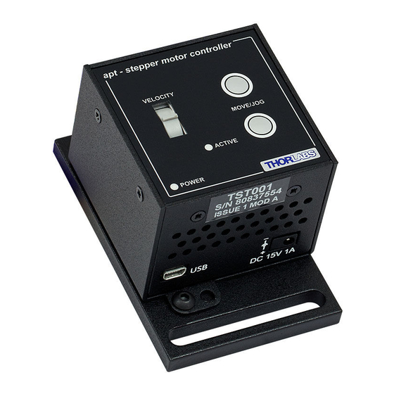
DC Servo Motor Driver 4.2 Control Panel Buttons and Indicators apt - dc servo controller VELOCITY MOVE/JOG ACTIVE POWER Fig. 4.1 Panel Controls and Indicators MOVE Controls - These controls allow all motor moves to be initiated. Move/Jog Buttons - Used to jog the motors and make discrete position increments in either direction - see Section 5.6. -
Page 22: Button Operation
Chapter 4 4.4 Button Operation The buttons on the front of the unit can be used to control the motor in a number of ways, as described below. 4.4.1 Homing A ‘Home’ move is performed to establish a datum from which subsequent absolute position moves can be measured (see Section 5.3. -
Page 23: Chapter 5 Pc Operation - Tutorial
(such as motor moves) can be initiated. Hardware configurations and parameter settings can be saved, which simplifies system set up whenever APT User is run up. Fig. 5.1 Typical APT User Screen 1) Run the APT User program - Start/Programs/Thorlabs/APT/APT User. -
Page 24: Ha0142T Rev 12 February
Chapter 5 2) Notice how the Z612(B) actuator type, selected in Section 3.5. is displayed in the ‘Settings’ window. See Section 5.10. and Section 6.3. for further details on the parameter values shown in the ‘Settings’ display. Fig. 5.2 DC Driver T-CubeSoftware GUI The APT User utility will be used throughout the rest of this tutorial to interface with the DC servo motor controller. -
Page 25: Homing Motors
DC Servo Motor Driver 5.3 Homing Motors Homing the motor moves the actuator to the home limit switch and resets the internal position counter to zero. The limit switch provides a fixed datum that can be found after the system has been powered up. Fig. -
Page 26: Moving To An Absolute Position
Chapter 5 5.4 Moving to an Absolute Position Absolute moves are measured in real world units (e.g. millimetres), relative to the Home position. 1) Click the position display. Fig. 5.4 Absolute Position Popup Window 2) Enter 3.0 into the pop up window 3) Click ‘OK’. -
Page 27: Changing Motor Parameters
DC Servo Motor Driver 5.5 Changing Motor Parameters Moves are performed using a trapezoidal velocity profile (see Appendix E , Section E.1.3.). The velocity settings relate to the maximum velocities at which a move is performed, and the acceleration at which the motor speeds up from zero to maximum velocity. -
Page 28: Jogging
Chapter 5 5.6 Jogging During PC operation, the motor actuators are jogged using the GUI panel arrow keys. There are two jogging modes available, ‘Single Step’ and ‘Continuous’. In ‘Single Step’ mode, the motor moves by the step size specified in the Step Distance parameter. -
Page 29: Graphical Control Of Motor Positions (Point And Move)
DC Servo Motor Driver 5.7 Graphical Control Of Motor Positions (Point and Move) The GUI panel display can be changed to a graphical display, showing the position of the motor channel(s). Moves to absolute positions can then be initiated by positioning the mouse within the display and clicking. - Page 30 Chapter 5 Move Mode When ‘Move’ is selected, the motors move to an absolute position which corresponds to the position of the cursor within the screen. To specify a move: 1) Position the mouse within the window. For reference, the absolute motor position value associated with the mouse position is displayed in the 'Cursor Position field.
-
Page 31: Setting Move Sequences
DC Servo Motor Driver 5.8 Setting Move Sequences This section explains how to set move sequences, allowing several positions to be visited without user intervention. For details on moving to absolute positions initiated by a mouse click – see Section 5.7. 1) From the Motor GUI Panel, select 'Move Sequencer' tab to display the Move Sequencer window. - Page 32 Chapter 5 3) Select 'New' to display the 'Move Editor' panel. Fig. 5.10 Move Editor Window Move data is entered/displayed as follows: Dist/Pos: - the distance to move from the current position (if 'Relative' is selected) or the position to move to (if 'Absolute' is selected). Dwell Time: - after the move is performed, the system can be set to wait for a specified time before performing the next move in the sequence.
- Page 33 DC Servo Motor Driver 5) Enter the required move data into the Move Editor and click OK. The move data is displayed in the main window as shown below. Fig. 5.11 Main Window with Move Data 6) Repeat step 4 as necessary to build a sequence of moves. Move data can be copied, deleted, cut/pasted and edited by right clicking the data line(s) and selecting the appropriate option in the pop up menu (shown below).
-
Page 34: Creating A Simulated Configuration
To create a simulated configuration proceed as follows: 1) Run the APT Config utility - Start/Programs/Thorlabs/APT/APT Config. 2) Click the 'Simulator Configuration' tab. Fig. 5.14 APT Configuration Utility - Simulator Configuration Tab 3) Enter ‘LAB 1’... - Page 35 4) In the 'Simulator' field, check the ‘Enable Simulator Mode’ box. The name of the most recently used configuration file is displayed in the 'Current Configuration' window. 5) In the ‘Control Unit’ field, select ‘1 Ch DC Driver T-Cube (TDC001)’.
- Page 36 Chapter 5 6) In the ‘Enter 6 digit serial number’ field, enter the serial number of your OptoDC unit. Note Each physical APT hardware unit is factory programmed with a unique 8 digit serial number. In order to simulate a set of ‘real’ hardware the Config utility allows an 8 digit serial number to be associated with each simulated unit.
-
Page 37: Stage/Axis Tab
APTUser. These parameters should not be altered for pre-defined Thorlabs stages and actuators selected using APT Config, as it may adversely affect the performance of the stage. -
Page 38: Chapter 6 Software Reference
Chapter 6 Software Reference 6.1 Introduction This chapter gives an explanation of the parameters and settings accessed from the APT software running on a PC. For information on the methods and properties which can be called via a programming interface, see Appendix D 6.2 GUI Panel The following screen shot shows the graphical user interface (GUI) displayed when accessing the DC Driver T-Cube using the APTUser utility. - Page 39 DC Servo Motor Driver Travel - displays the range of travel (in millimeters or degrees) of the motor. Moving - lit when the motor is in motion. Enable - applies power to the motor. With the motor enabled, the LED in the button is lit.
-
Page 40: Settings Panel
Chapter 6 6.3 Settings Panel When the 'Settings' button on the GUI panel is clicked, the 'Settings' window is displayed. This panel allows motor operation parameters such as move/jog velocities, and stage/axis information to be modified. Note that all of these parameters have programmable equivalents accessible through the ActiveX methods and properties on this Control (refer to the Programming Guide in the APTBase helpfile for further details and to Section 2.3.4. - Page 41 DC Servo Motor Driver Jogs Jogs are initiated by using the ‘Jog’ keys on the GUI panel (see Section 5.6.), or the Jog Buttons on the front panel of the unit. Velocity Profile (specified in real world units, millimetres or degrees) Note In current versions of software, the ‘Min Vel’...
- Page 42 Chapter 6 Stopping - the way in which the jog motion stops when the demand is removed. Immediate - the motor stops quickly, in a non-profiled manner Profiled - the motor stops in a profiled manner using the jog Velocity Profile parameters set above.
-
Page 43: Stage/Axis Tab
For Thorlabs stages, the APT Config utility can be used to associate a specific stage and axis type with the motor channel (refer to the tutorial in Section 3.5. - Page 44 Chapter 6 Stage and Axis Type - For Thorlabs stages, the stage type is displayed automatically once the axis has been associated using the APTConfig utility. For third party stages, the display shows ‘Unknown’. Min Pos - the stage/actuator minimum position (typically zero).
- Page 45 DC Servo Motor Driver Motor These parameters are used to set the 'resolution' characteristics of the DC servo motor connected to the selected channel. The resolution of the motor, combined with other characteristics (such as lead screw pitch) of the associated actuator, determines the overall resolution.
-
Page 46: Advanced Tab
Chapter 6 Persist Settings to Hardware - Many of the parameters that can be set for the DC Driver T-Cube can be stored (persisted) within the unit itself, such that when the unit is next powered up these settings are applied automatically. This is particularly important when the driver is being used manually in the absence of a PC and USB link. - Page 47 DC Servo Motor Driver Motor Moving: When this option is selected, the Active LED is lit when the motor is moving. It is recognised that, in a light sensitive environment stray light from the LED could be undesirable. Therefore it is possible to disable selectively, one or all of the LED indicator modes described above by clearing the associated check boxes in the ‘LED Indicator Modes’...
- Page 48 Chapter 6 Servo Loop (PID) Control Settings The DC Driver T-Cube implements a full servo control loop for motor velocity and position control. The loop response to demanded position moves is determined via Proportional, Integration and Derivative settings. These settings can be altered using the ‘Servo Loop (PID) Control Settings’...
- Page 49 DC Servo Motor Driver Note The following parameters are applicable only if ‘Go to Position is selected in the ‘Button Mode’ field. Left/Top Button Position: The position to which the motor will move when the top button is pressed. Right/Bottom Button Position: The position to which the motor will move when the bottom button is pressed.
-
Page 50: Appendix A Rear Panel Connector Pinout Detail
Encoder Channel B Not Connected Not Connected Motor + Not Connected Not Connected Not Connected Fig. A.1 MOTOR I/O Connector Pin Identification A 15 Pin DIN to 10 Pin IDC converter (Z600-TCAB1) is available for use with Thorlabs legacy DC Servo Motors. -
Page 51: Appendix B Preventive Maintenance
The equipment contains no user servicable parts. There is a risk of electrical shock if the equipment is operated with the covers removed. Only personnel authorized by Thorlabs Ltd and trained in the maintenance of this equipment should remove its covers or attempt any repairs or adjustments. Maintenance is limited to safety testing and cleaning as described in the following sections. -
Page 52: Appendix C Specifications And Associated Products
Appendix C Specifications and Associated Products C.1 Specifications Parameter Value Motor Output Motor Drive Voltage ±12 to ±15V (Depending on Supply) Motor Drive Current 200mA (peak) Motor Drive Type 8-bit Sign/Magnitude PWM Control Algorithm Digital PID Filter (16bit) Position Feedback: 5V Single Ended Quadrature Encoder (QEP) Input Encoder Feedback Bandwidth... - Page 53 DC Servo Motor Driver Recommended Motor Requirements Peak Power 2.5W Rated Current 0mA to 150mA Motor Type Brushed DC Coil Resistance 5 to 50Ω Coil Inductance 250 to 1500mH Position Control Closed loop Encoder Resolution Encoder Specific Peak Power 2.5W Rated Current 0mA to 150mA Motor Type...
-
Page 54: Appendix D Motor Control Method Summary
Appendix D Motor Control Method Summary The 'Motor' ActiveX Control provides the functionality required for a client application to control one or more of the APT series of motor controller units. To specify the particular controller being addressed, every unit is factory programmed with a unique 8-digit serial number. - Page 55 DC Servo Motor Driver GetHWCommsOK Gets the hardware communications OK flag. GetHWLimSwitches Gets the limit switch configuration settings. GetIndicatorLEDMode Gets the front panel indication LED operating mode. GetJogMode Gets the jogging button operating modes. GetJogMode_Mode Get the jogging button operating mode (returned by value).
- Page 56 Appendix D GetStageAxisInfo_MinPos Gets the stage minimum position (returned by value). GetStatusBits_Bits Gets the controller status bits encoded in 32 bit integer (returned by value). GetVelParamLimits Gets the maximum velocity profile parameter limits. GetVelParams Gets the velocity profile parameters. GetVelParams_Accn Gets the move acceleration (returned by value).
- Page 57 DC Servo Motor Driver SetJogMode Sets the jogging button operating modes. SetJogStepSize Sets the jogging step size. SetJogVelParams Sets the jogging velocity profile parameters. SetMotorParams Sets the motor gearing parameters. SetPositionOffset Sets the motor position offset. SetPotParams Sets the velocity control potentiometer parameters SetRelMoveDist Sets the relative move distance.
-
Page 58: Appendix Edc Motor Operation - Background
Appendix E DC Motor Operation - Background E.1 How A DC Motor Works E.1.1 General Principle A DC motor works by converting electric power into mechanical energy (movement). This is achieved by forcing current through a coil and producing a magnetic field, which in turn, spins the motor. - Page 59 DC Servo Motor Driver Both forces are of equal magnitude. At 180°, the same phenomenon occurs, but segment A-B is forced down and C-D is forced up. In the 90° and 270° positions, the brushes are not in contact with the voltage source and no force is produced. In these two positions, the rotational kinetic energy of the motor keeps it spinning until the brushes regain contact.
- Page 60 Appendix E E.2 Positioning a Stage E.2.1 General Whenever a command is received to move a stage, the movement is specified in motion units, (e.g. millimetres). This motion unit value is converted to encoder counts before it is sent to the stage by the APT software. Each motor in the system has an associated electronic counter in the controller, which keeps a record of the net number of encoder counts moved.
- Page 61 DC Servo Motor Driver Datum switch +ve limit switch -ve limit switch (or stop) Linear stage Rotary stage Fig. E.3 Stage limit switches E.2.4 Minimum and Maximum Positions These positions are dependent upon the stage or actuator to which the motors are fitted, and are defined as the minimum and maximum useful positions of the stage relative to the ‘Home’...
- Page 62 Appendix E E.3 Error Correction E.3.1 Backlash correction The term backlash refers to the tendency of the stage to reach a different position depending on the direction of approach. Backlash can be overcome by always making the last portion of a move in the same direction, conventionally the positive direction.
-
Page 63: Appendix F Regulatory
Appendix F Regulatory F.1 Declarations Of Conformity F.1.1 For Customers in Europe This equipment has been tested and found to comply with the EC Directives 89/336/EEC ‘EMC Directive’ and 73/23/EEC ‘Low Voltage Directive’ as amended by 93/68/EEC. Compliance was demonstrated by conformance to the following specifications which have been listed in the Official Journal of the European Communities: Safety EN61010: 2001 Installation Category II, Polution Degree II. - Page 64 • left over parts of units disassembled by the user (PCB's, housings etc.). If you wish to return a unit for waste recovery, please contact Thorlabs or your nearest dealer for further information. HA0142T Rev 12 February 2011...
-
Page 65: Appendix G Thorlabs Worldwide Contacts
DC Servo Motor Driver F.2.2 Waste treatment on your own responsibility If you do not return an "end of life" unit to the company, you must hand it to a company specialized in waste recovery. Do not dispose of the unit in a litter bin or at a public waste disposal site. - Page 66 Appendix F HA0142T Rev 12 February 2011...
- Page 67 DC Servo Motor Driver Appendix G Thorlabs Worldwide Contacts USA, Canada, and South America Scandinavia Thorlabs, Inc. Thorlabs Sweden AB 435 Route 206 Box 141 94 Newton, NJ 07860 400 20 Göteborg Sweden Tel: 973-579-7227 Tel: +46-31-733-30-00 Fax: 973-300-3600 Fax: +46-31-703-40-45 www.thorlabs.com...
- Page 68 Thorlabs Inc. Thorlabs Ltd. 435 Route 206 North Saint Thomas Place, Ely Newton, NJ07860 Cambridgeshire CB7 4EX, Tel: +1 973 579 7227 Tel: +44 (0) 1353 654440 Fax: +1 973 300 3600 Fax: +44 (0) 1353 654444 www.thorlabs.com www.thorlabs.com...
Need help?
Do you have a question about the TDC001 and is the answer not in the manual?
Questions and answers