Table of Contents
Advertisement
Quick Links
Advertisement
Table of Contents

Related Manuals for THORLABS KBD101


Summary of Contents for THORLABS KBD101
- Page 1 KBD101 K-Cube Brushless DC Servo Driver User Guide Original Instructions...
-
Page 2: Table Of Contents
Contents Chapter 1 Safety ..................... 4 1.1 Safety Information .................. 4 1.2 General Warnings .................. 4 Chapter 2 Overview and Setup ..............5 2.1 Introduction ..................... 5 2.2 APT PC Software Overview ..............7 2.2.1 Introduction......................7 2.2.2 APTUser Utility ....................8 2.2.3 APT Config Utility .................... - Page 3 Appendix A Rear Panel Connector Pinout Details ........70 Appendix B Preventive Maintenance ............71 Appendix C Specifications and Associated Parts ........72 Appendix D Motor Control Method Summary ........... 73 Appendix E Regulatory ................77 Appendix F Thorlabs Worldwide Contacts ..........80...
-
Page 4: Chapter 1 Safety
To minimize the possibility of this happening it is strongly recommended that any such modes that result in prolonged unresponsiveness be disabled before the APT software is run. Please consult your system administrator or contact Thorlabs technical support for more details. -
Page 5: Chapter 2 Overview And Setup
Chapter 2 Overview and Setup 2.1 Introduction The KBD101 Brushless DC Motor K-Cubes are ideal for motion control applications demanding high speed (100s of mm/s) and high encoder resolution (<100 nm) operation. These single channel drivers offer high-precision motion control in a wide range of applications, and in particular when used along with our DDSM100 fast translation stage where speeds of up to 500 mm/sec can be achieved. - Page 6 For power, a single way wall plug supply (KPS101) is also available for powering a single K-Cube Driver. As a further level of convenience when using the new K-Cube Controllers Thorlabs also offers the 3-channel and 6-channel K-Cube Controller Hubs (KCH301 and KCH601).
-
Page 7: Apt Pc Software Overview
2.3 APT PC Software Overview 2.3.1 Introduction As a member of the APT range of controllers, the KBD101 Brushless DC motor driver shares many of the associated software benefits. This includes USB connectivity (allowing multiple units to be used together on a single PC), fully featured Graphical User Interface (GUI) panels, and extensive software function libraries for custom application development. -
Page 8: Aptuser Utility
Chapter 2 2.3.2 APTUser Utility The APTUser application allows the user to interact with a number of APT hardware control units connected to the host PC. This program displays multiple graphical instrument panels to allow multiple APT units to be controlled simultaneously. All basic operating parameters can be altered and, similarly, all operations (such as motor moves) can be initiated. -
Page 9: Apt Config Utility
If a KBD101 driver is used with the DDSM100 Direct Drive Translation stage, all stage-associated settings are made automatically when the stage is connected to the driver. - Page 10 Visual Basic, Labview, Visual C++, C++ Builder, HPVEE, Matlab, VB.NET, C#.NET and, via VBA, Microsoft Office applications such as Excel and Word. Consider the ActiveX Control supplied for the KBD101 APT Brushless DC Servo driver unit. This Control provides a complete user graphical instrument panel to allow the motor...
-
Page 11: Software Upgrades
APT ActiveX Controls collection. This is available either by pressing the F1 key when running the APT server, or via the Start menu, Start\Programs\Thorlabs\APT\APT Help. 2.3.5 Software Upgrades Thorlabs operate a policy of continuous product development and may issue software upgrades as necessary. -
Page 12: Chapter 3 Getting Started
To minimize the possibility of this happening it is strongly recommended that any such modes that result in prolonged unresponsiveness be disabled before the APT software is run. Please consult your system administrator or contact Thorlabs technical support for more details. Caution Some PCs may have been configured to restrict the users ability to load software, and on these systems the software may not install/run. -
Page 13: Mechanical Installation
(KCH301 and KCH601). ) are also available - see Section 2.2. for further details. Full instructions on the fitting and use of the controller hub are contained in the handbook available at www.thorlabs.com Caution When siting the unit, it should be positioned so as not to impede the operation of the control panel buttons. -
Page 14: Using The Baseplate
Chapter 3 3.2.3 Using the Baseplate The baseplate must be bolted to the worksurface before the K-Cube is fitted, as shown below. The K-cube is then located on two dowels in the baseplate and secured by two clips. Fig. 3.1 Using The Baseplate 3.3 Electrical Installation 3.3.1 Rear Panel Fig. -
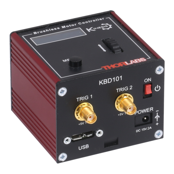
Page 15: Front Panel
DC power supply of 15 V, 2A. Thorlabs offers a compact, multi-way power supply unit (TPS008), allowing up to four KBD101 K-Cubes to be powered from a single mains outlet. A single way wall plug supply (KPS101) for powering a single Driver K-Cube is also available. -
Page 16: Connect The Hardware
Chapter 3 3.4 Connect The Hardware 1) Perform the mechanical installation as detailed in Section 3.2. 2) Install the APT Software. Caution During items (3) to (6) the instructions should be followed strictly in the order stated. Problems may occur if the process is not performed in the correct sequence. - Page 17 Brushless DC Servo Driver K-Cube The unit takes about 5 seconds from power application until warm up is finished, and phase initialization is complete. During this time the following screens are displayed. T h o r l a b s K B D 1 0 1 S w R e v 1 0 0 0 2 S t a g e c o n n e c t e d : D D S M 1 0 0...
-
Page 18: Chapter 4 Standalone Operation
4.1 Introduction The Brushless DC Driver K-Cube has been designed specifically to operate with the range of Thorlabs Brushless DC motorised opto-mechanical products. The unit offers a fully featured motion control capability including velocity profile settings, limit switch handling, homing sequences and, for more advanced operation, adjustment of PID settings, allowing support for many different actuator configurations. -
Page 19: Digital Display - Operating Mode
Brushless DC Servo Driver K-Cube 4.2.1 Digital Display - Operating Mode During normal operation, the digital display shows the current position (in millimeters or degrees) and the current state of the motor (Stopped or Moving). If the stage being driven has been homed, the display will also show ‘Homed’. Brushless Motor Controller A t 0 . -
Page 20: Velocity Wheel Operation
Chapter 4 This mode of operation is enabled by setting the ‘Wheel Mode’ to ‘Go To Position’ through the software GUI - see Section 6.3.3. or via the display menu, see Section 4.4.6. Note for Rotation Stage Users If the current absolute position is outside the 0 to 360 degree range, then "go to position"... -
Page 21: Settings Menu
Brushless DC Servo Driver K-Cube 4.4 Settings Menu 4.4.1 Overview A t 0 . 0 0 0 0 m m S t o p p e d Press the MENU button MENU Use the wheel to scroll through the menu options M e n u o p t i o n s U s e w h e e l Press the MENU button to enter a particular option... - Page 22 Chapter 4 4.4.2 Menu Option - Enable/Disable After initial start up the drive channel is disabled, and A t 0 . 0 0 0 0 m m must be enabled before the stage can be driven. D i s a b l e d MENU Press the MENU button, then use the wheel to scroll M e n u o p t i o n s...
- Page 23 Brushless DC Servo Driver K-Cube 4.4.3 Menu Option - Go to position A t 0 . 0 0 0 0 m m This mode is used to move to an absolute position. S t o p p e d MENU Press the MENU button, then use the wheel to scroll through the menu options.
- Page 24 Chapter 4 4.4.4 Menu Option - Start homing This mode is used to home the stage. A t 2 . 0 0 0 0 m m S t o p p e d MENU Press the MENU button, then use the wheel to scroll through the menu options.
- Page 25 Brushless DC Servo Driver K-Cube 4.4.6 Menu Option - Joystick Mode A t 0 . 0 0 0 0 m m This mode is used to set the operating mode of the H o m e d S t o p p e d V joystick wheel.
- Page 26 Chapter 4 4.4.7 Menu Option - Jog Step Size A t 0 . 0 0 0 0 m m This mode is used to set the jog step size. H o m e d S t o p p e d V MENU Press the MENU button, then use the wheel to scroll through the menu options.
- Page 27 Brushless DC Servo Driver K-Cube 4.4.8 Menu Option - Teach Position This mode is used to set the teach positions, used when the Joystick mode option is set to Jog to positions mode - see Section 4.4.6. To set Teach Position 1... A t 1 0 .
- Page 28 Chapter 4 4.4.9 Menu Option - Brightness A t 0 . 0 0 0 0 m m In certain applications, it may be necessary to adjust the H o m e d S t o p p e d V brightness of the LED display.
-
Page 29: External Triggering
Brushless DC Servo Driver K-Cube 4.5 External Triggering External triggering is facilitated by the ‘TRIG 1’ and ‘TRIG 2 connectors on the front panel of the unit - see Section 3.3.2.. These connectors are controlled via the APT software (see Section 6.3.4.) and provide a 5V logic level input/output that can be configured to support triggering from and to external devices. -
Page 30: Trigger Out
Chapter 4 4.5.3 Trigger Out CMOS Logic Gate 470R Connector Protection Fig. 4.4 TRIG OUT Connection Detail The TRIG output is the output of a standard 5V CMOS logic gate in series with a 470 resistor. The resistor provides protection against accidentally short circuiting to ground by limiting the current to approx 10 mA maximum. -
Page 31: Chapter 5 Pc Operation - Tutorial
However, if the output is disabled (with the driver connected and monitoring the position) and the stage is moved manually at high speeds, it is possible to exceed this limit. If the KBD101 driver is subsequently used again to move the stage, the incorrect encoder reading will cause incorrect operation, often resulting in sudden uncontrolled moves. -
Page 32: Verifying Software Operation
Chapter 5 5.2 Verifying Software Operation 5.2.1 Initial Setup The APT Software should be installed (Section 3.1.) and the power up procedure performed (Section 3.3.) before software operation can be verified. 1) Run the APTUser utility and check that the Graphical User Interface (GUI) panel appears and is active. -
Page 33: Using The Apt User Utility
(such as motor moves) can be initiated. Hardware configurations and parameter settings can be saved to a file, which simplifies system set up whenever APT User is run up. Fig. 5.2 Typical APT User Screen 1) Run the APT User program - Start/All Programs/Thorlabs/APT User/APT User. -
Page 34: Homing Motors
Chapter 5 5.4 Homing Motors The need for homing comes from the fact that on power up the motor (stage) is at a random position, so the value of the position counter is meaningless. Homing involves moving the motor to a known reference marker and resetting the position counter to the associated absolute value. -
Page 35: Moving To An Absolute Position
Brushless DC Servo Driver K-Cube 5.5 Moving to an Absolute Position Absolute moves are measured in real world units (e.g. millimetres), relative to the Home position. 1) Click the position display. Fig. 5.4 Absolute Position Popup Window 2) Enter 3.0 into the pop up window 3) Click ‘OK’. -
Page 36: Changing Motor Parameters
Chapter 5 5.6 Changing Motor Parameters Note Moves are performed using a Trapezoidal or S-Curve velocity profile (see Section 6.3.4.). The velocity settings relate to the maximum velocity at which a move is performed, and the acceleration at which the motor speeds up from zero to maximum velocity. -
Page 37: Jogging
Brushless DC Servo Driver K-Cube 5.7 Jogging During PC operation, the motor actuators are jogged using the GUI panel arrow keys. There are two jogging modes available, ‘Single Step’ and ‘Continuous’. In ‘Single Step’ mode, the motor moves by the step size specified in the Step Distance parameter each time the key is pressed. -
Page 38: Graphical Control Of Motor Positions (Point And Move)
Note The channel functionality of the KBD101 driver is accessed via a single channel GUI panel, so the settings for channel 2 are greyed out. The left hand display shows a circle, which represents the current position of the motor associated with the specified controller (absolute position data is displayed in the 'Chan Pos' field). -
Page 39: Loading Parameter Settings
Brushless DC Servo Driver K-Cube Move Mode When ‘Move’ is selected, the motors move to an absolute position which corresponds to the position of the cursor within the screen. To specify a move: 1) Position the mouse within the window. For reference, the absolute motor position values associated with the mouse position is displayed in the 'Cursor Position field. -
Page 40: Setting Move Sequences
Chapter 5 5.10 Setting Move Sequences This section explains how to set move sequences, allowing several positions to be visited without user intervention. For details on moving to absolute positions initiated by a mouse click – see Section 5.8. 1) From the Motor GUI Panel, select 'Move Sequencer' tab to display the Move Sequencer window. - Page 41 Brushless DC Servo Driver K-Cube 3) Select 'New' to display the 'Move Editor' panel. Fig. 5.10 Move Editor Window Move data is entered/displayed as follows: Dist/Pos: - the distance to move from the current position (if 'Relative' is selected) or the position to move to (if 'Absolute' is selected) (values entered in mm).
- Page 42 Chapter 5 4) Enter the required move data into the Move Editor and click OK. The move data is displayed in the main window as shown below. Fig. 5.11 Main Window with Move Data 5) Repeat step 4 as necessary to build a sequence of moves. Move data can be copied, deleted, cut/pasted and edited by right clicking the data line(s) and selecting the appropriate option in the pop up menu (shown below).
-
Page 43: Creating A Simulated Configuration Using Apt Config
To create a simulated configuration proceed as follows: 1) Run the APT Config utility - Start/All Programs/Thorlabs/APT/APT Config. 2) Click the 'Simulator Configuration' tab. Fig. 5.14 APT Configuration Utility - Simulator Configuration Tab... - Page 44 8 digits (as displayed in the ‘Load Configuration Details’ window, the first two digits are added automatically and identify the type of control unit. The Prefixed digits for the KBD101 Brushless DC Motor K-Cube are 28xxxxxx. HA0364T Rev C Aug 2022...
- Page 45 Brushless DC Servo Driver K-Cube 5) In the ‘Control Unit’ field, select ‘1 Ch Brushless Drive K-Cube (KBD101)’. 6) Enter a 6 digit serial number. 7) Click the 'Add' button. 8) Repeat items (1) to (7) to build the required system. (A unit can be removed from...
-
Page 46: Chapter 6 Software Reference
Chapter 6 Software Reference 6.1 Introduction This chapter gives an explanation of the parameters and settings accessed from the APT software running on a PC. For information on the methods and properties which can be called via a programming interface, see Appendix D 6.2 GUI Panel The following screen shot shows the graphical user interface (GUI) displayed when accessing the DC driver using the APTUser utility. - Page 47 Calib File - the calibration file associated with the specified channel. Note Calibration files are not applicable for the Thorlabs Brushless DC motor stages such as the DDSM100. Min/Max V - the minimum velocity at which a move is initiated, and the maximum velocity at which the move is performed.
-
Page 48: Settings Panel
Chapter 6 6.3 Settings Panel When the 'Settings' button on the GUI panel is clicked, the 'Settings' window is displayed. This panel allows motor operation parameters such as move/jog velocities, and stage/axis information to be modified. Note that all of these parameters have programmable equivalents accessible through the ActiveX methods and properties on this Control (refer to the Programming Guide in the APTServer helpfile for further details and to Section 2.3.4. - Page 49 Brushless DC Servo Driver K-Cube Note Under certain velocity parameter and move distance conditions, the maximum velocity may never be reached (i.e. the move comprises an acceleration and deceleration phase only). The limits for the max velocity or acceleration parameters are dependent on the stage being driven.
- Page 50 Chapter 6 motor actuator will accelerate and move at the jog velocity while the button is held down.. Single Step mode velocity jog step size jog velocity distance button button button pressed pressed pressed Continuous mode velocity button released jog velocity jog acceleration distance Fig.
- Page 51 Note. Setting a negative value for backlash correction also results in zero correction. Persist Settings to Hardware - Many of the parameters that can be set for the KBD101 series drivers can be stored (persisted) within the unit itself, such that when the unit is next powered up these settings are applied automatically.
-
Page 52: Stage/Axis Tab
They need to be set accordingly such that a particular stage is driven properly by the system. For Thorlabs stages, the APT server will automatically apply suitable defaults for the parameters on this tab during boot up of the software. - Page 53 Brushless DC Servo Driver K-Cube Note The Min Pos and Max Pos parameters can be used to restrict the working range of the stage to a particular area of interest. Pitch - the pitch of the motor lead screw (i.e. the distance (in mm or degrees) travelled per revolution of the leadscrew).
- Page 54 Persist Settings to Hardware - Many of the parameters that can be set for the KBD101 series drivers can be stored (persisted) within the unit itself, such that when the unit is next powered up these settings are applied automatically.
-
Page 55: Advanced - Control Loop Settingstab
Fig. 6.5 Advanced Control Loop Settings Position Loop Control Settings The motion processors within the KBD101 driver uses a position control loop to determine the motor command output. The purpose of the position loop is to match the actual motor position and the demanded position. This is achieved by comparing the demanded position with the actual encoder position to create a position error, which is then passed through a digital PID-type filter. - Page 56 Chapter 6 this can lead to overshoot and general instability. If this is too low it can result in a sloppy response. It accepts values in the range 0 to 32767. Integral term - Increasing the integral (Int) term minimises following error and final position error.
- Page 57 Brushless DC Servo Driver K-Cube Position PID Settings Summary Stage overshoots the intended position - reduce Int and increase Deriv and Prop terms. Stage doesn't attain final position - increase the Int and Prop terms. Motion is unstable - reduce Prop and Int, increase Deriv. Stage sounds noisy - reduce Deriv.
-
Page 58: Advanced - Misc. Tab
Chapter 6 Persist Settings to Hardware - Many of the parameters that can be set for the KBD101 series drivers can be stored (persisted) within the unit itself, such that when the unit is next powered up these settings are applied automatically. This is particularly important when the driver is being used manually via a joystick, in the absence of a PC and USB link. - Page 59 Brushless DC Servo Driver K-Cube maximum, in the range 0% to 100%. When the accumulated energy exceeds the value specified in the Energy Limit parameter, a 'current foldback' condition is said to exist, and the commanded current is limited to the value specified in the Current Limit parameter. When this occurs, the Current Foldback status bit (bit 25) is set in the Status Register and the ‘Current Limit’...
- Page 60 Chapter 6 Position Err Limit parameter set in the Advanced - Control Loop Settings tab, the axis is not stopped if it moves outside the specified tracking window. This function is useful for processes that rely on the motor's correct tracking of a set trajectory within a specific range.
- Page 61 Brushless DC Servo Driver K-Cube velocity maximum velocity (v) acceleration (slope) a time Fig. 6.7 Graph of a trapezoidal velocity profile The S-curve profile is a trapezoidal curve with an additional 'Jerk' parameter, which limits the rate of change of acceleration and smooths out the contours of the motion profile. Jerk Setting –...
-
Page 62: Panel/Triggering Tab
Chapter 6 6.3.5 Panel/Triggering Tab Adjustment Wheel Settings The velocity wheel is sprung such that when released it returns to it’s central position. In this central position the motor is stationary. As the wheel is moved away from the center, the motor begins to move; the speed of this movement increases as the wheel deflection is increased. - Page 63 Brushless DC Servo Driver K-Cube Wheel Direction The direction of a move initiated by the velocity wheel is specified as follows: Disabled - The wheel is disabled to remove any unwanted motion due to accidental movement of the wheel. Direction Sense Positive - Upwards rotation of the wheel results in a positive motion (i.e.
- Page 64 Chapter 6 Triggering Introduction The K-Cube motor controllers have two bidirectional trigger ports (TRIG1 and TRIG2) that can be used to read an external logic signal or output a logic level to control external equipment. Either of them can be independently configured as an input or an output and the active logic state can be selected High or Low to suit the requirements of the application.
- Page 65 Brushless DC Servo Driver K-Cube Output Trigger Modes When the Trig 1 Mode and Trig 2 Mode parameters are configured as outputs, the TRIG ports can be used as a general purpose digital output, or to indicate motion status or to produce a trigger pulse at configurable positions as follows: Digital Output - General purpose logic output (set using the LLSetGetDigOPs method).
- Page 66 Chapter 6 Cycles) allows the uni- or bidirectional position triggering sequence to be repeated a number of times. PosIntervalFwd 15 mm Pos2 Fwd 12 mm Pos1 Rev StartPosRev 10 mm StartPosFwd Pos1 Fwd Time Trig Voltage Time Fig. 6.9 Position Steps Triggering Example for a move from 0 to 20 mm and back.
-
Page 67: Triggering Latency
Brushless DC Servo Driver K-Cube 6.3.6 Triggering Latency The detection of whether a trigger condition has occurred is carried out periodically at 102 µs intervals. As a result, there is a maximum 102 µs delay between the condition occurring and the trigger output being updated. The following timing diagram illustrates this latency: Trigger condition occurs time... -
Page 68: Troubleshooting And Restoring Default Parameters
Chapter 6 Absolute Position Reporting Mode This setting relates to the way in which the angular position is displayed on the GUI panel. There are two options: Equivalent Angle 0 to 360 degrees – The maximum displayed position is 359.99°. If a stage is driven past the 360°... - Page 69 Brushless DC Servo Driver K-Cube If adjustment of the parameter values previously described has resulted in unstable or unsatisfactory system response, this tab can be used to reset all parameter values to the factory default settings. To restore the default values: 1) Select the ‘Defaults’...
-
Page 70: Appendix A Rear Panel Connector Pinout Details
Quadrature X+/-: Differential quadrature pulses of the encoder Encoder Index I -/+: The differential Index pulse used for homing Limit -/+: Positive and negative limit switch signals Stage ID: Unique Thorlabs communication interface signal used to identify the stage connected. MOTOR DRIVE Fig. -
Page 71: Appendix B Preventive Maintenance
The equipment contains no user servicable parts. There is a risk of electrical shock if the equipment is operated with the covers removed. Only personnel authorized by Thorlabs Ltd and trained in the maintenance of this equipment should remove its covers or attempt any repairs or adjustments. -
Page 72: Appendix C Specifications And Associated Parts
Appendix C Specifications C.1 Specifications Parameter Value Drive Connector 15-Pin D-Type, Female (Motor Phase Outputs, Stage ID Input) Peak Current Output PWM Frequency 40 kHz Operating Modes Position, Velocity Control Algorithm 16-bit Digital PID Servo Loop with Velocity and Acceleration Feedforward Velocity Profile Trapezoidal/S-Curve Position Count... -
Page 73: Appendix D Motor Control Method Summary
Appendix D Motor Control Method Summary The 'Motor' ActiveX Control provides the functionality required for a client application to control one or more of the APT series of motor controller units. To specify the particular controller being addressed, every unit is factory programmed with a unique 8-digit serial number. - Page 74 Appendix D GetDCSettledCurrentLoopParams Gets the Current servo loop PID parameter settings applied when the unit is ‘settled’. GetDCTriggerParams Gets the present Trigger Mode settings. GetDispMode Gets the GUI display mode. GetHomeParams Gets the homing sequence parameters. GetHomeParams_HomeVel Gets the homing velocity parameter (returned by value).
- Page 75 Brushless DC Servo Driver K-Cube GetStageAxisInfo_MaxPos Gets the stage maximum position (returned by value). GetStageAxisInfo_MinPos Gets the stage minimum position (returned by value). GetStatusBits_Bits Gets the controller status bits encoded in 32 bit integer (returned by value). GetVelParamLimits Gets the maximum velocity profile parameter limits. GetVelParams Gets the velocity profile parameters.
- Page 76 Appendix D SetDCMotorOutputParams Sets the limits that are applied to the motor drive signal SetDCTrackSettleParams Sets the parameters for the Track and Settle windows SetDCProfileModeParams Sets the parameters for the profile mode SetDCJoystickParams Sets the values for the joystick max velocity and acceleration SetDCSettledCurrentLoopParams Sets the Current servo loop PID parameter settings...
-
Page 77: Appendix E Regulatory
Appendix E Regulatory E.1 Declarations Of Conformity E.1.1 For Customers in Europe See Section E.2. E.1.2 For Customers In The USA This equipment has been tested and found to comply with the limits for a Class A digital device, persuant to part 15 of the FCC rules. These limits are designed to provide reasonable protection against harmful interference when the equipment is operated in a commercial environment. - Page 78 Appendix E E.2 CE Certificate HA0364T Rev C Aug 2022...
-
Page 79: Appendix F Thorlabs Worldwide Contacts
"End of life" units must be returned to Thorlabs or handed to a company specializing in waste recovery. Do not dispose of the unit in a litter bin or at a public waste disposal site. - Page 80 www.thorlabs.com...
Need help?
Do you have a question about the KBD101 and is the answer not in the manual?
Questions and answers