Table of Contents
Advertisement
Quick Links
Advertisement
Table of Contents

Related Manuals for THORLABS ODC001


Summary of Contents for THORLABS ODC001
- Page 1 OPTODC SERVO MOTOR DRIVER Model Number ODC001...
- Page 2 THORLABS About the Company Thorlabs is a broad based optical technologies company with expertise in the design and manufacture of an extensive array of innovative photonics products. The product range covers optical and opto-mechanical components, tables and vibration control, nanopositioning solutions, test and measurement systems, and laser sources.
-
Page 3: Table Of Contents
Contents 1 For Your Safety ..................3 Safety Information ......................3 Warnings ........................4 Declarations Of Conformity .................... 4 For Customers in Europe ..................4 For Customers In The USA ..................4 Waste Electrical and Electronic Equipment (WEEE) Directive ........5 Compliance ...................... - Page 4 4 PC Operation - Tutorial ................20 Introduction ........................21 Select the Stage Type (using APTConfig) ..............21 Using the APT User Utility .................... 23 Homing Motors ......................25 Moving to an Absolute Position ..................26 Changing Motor Parameters ..................27 Jogging .........................
-
Page 5: For Your Safety
Chapter 1 For Your Safety 1.1 Safety Information For the continuing safety of the operators of this equipment, and the protection of the equipment itself, the operator should take note of the Warnings, Cautions and Notes throughout this handbook. The following safety symbols may be used throughout the handbook: Warning. -
Page 6: Warnings
1.2 Warnings • The unit must be connected only to a DC supply of 12-15V, 1A regulated. Thorlabs offer a compact, multi-way power supply unit (OPS008), allowing up to eight OptoDrivers to be powered from a single mains outlet. A single way wall plug supply (OPS001) for powering a single OptoDriver is also available. -
Page 7: Waste Electrical And Electronic Equipment (Weee) Directive
Fig. 1.1 Crossed out "wheelie bin" symbol As the WEEE directive applies to self contained operational electrical and electronic products, this "end of life" take back service does not refer to other Thorlabs products, such as •... -
Page 8: Waste Treatment On Your Own Responsibility
1.4.2 Waste treatment on your own responsibility If you do not return an "end of life" unit to Thorlabs, you must hand it to a company specialized in waste recovery. Do not dispose of the unit in a litter bin or at a public waste disposal site. -
Page 9: Overview And Setup
DC brushed motors up to 5V operation equipped with encoder feedback. This driver unit (a direct replacement for the DCX-MC110B controller modules featured in earlier editions of the Thorlabs catalogue) contains a full embedded controller and driver circuit that can be operated with and without a PC. -
Page 10: Mechanical Installation
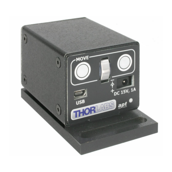
Chapter 2 Overview and Setup Designed as a direct replacement for the earlier Thorlabs DC controller module (DCX- MC110B) and associated PCI carrier board (DCX-PCI100), the new OptoDCDriver is contained in a very compact (2.5" x 2" x 1.6") housing incorporating easily accessible local motor move controls for manual motor control and positioning. -
Page 11: Environmental Conditions
ODC001 Servo Motor Driver 2.2.2 Environmental Conditions Warning. Operation outside the following environmental limits may adversely affect operator safety. Location Indoor use only Maximum altitude 2000 m Temperature range C to 40 Maximum Humidity Less than 80% RH (non-condensing) at 31°C To ensure reliable operation the unit should not be exposed to corrosive agents or excessive moisture, heat or dust. -
Page 12: Electrical Installation
DC Servo Controller Motor Fig. 2.4 Rear Panel Connections The unit is supplied with a 10 pin IDC connector as shown above, which is compatible with all Thorlabs DC servo motor actuators (refer to Appendix A for details of pin outs). -
Page 13: Installing Apt Software For Pc Operation
HKEY_LOCAL_MACHINE\SOFTWARE\THORLABS\APT USER For further information, consult your system administrator. 2.4.3 Software Upgrades Thorlabs operate a policy of continuous product development and may issue software upgrades as necessary. Detailed instructions on installing upgrades are included on the APT Software CD ROM. -
Page 14: Apt Pc Software Overview
Chapter 2 Overview and Setup 2.5 APT PC Software Overview 2.5.1 Introduction As a member of the APT range of controllers, the OptoDCDriver shares many of the associated software benefits. This includes USB connectivity (allowing multiple units to be used together on a single PC), fully featured Graphical User Interface (GUI) panels, and extensive software function libraries for custom application development. -
Page 15: Aptuser Utility
ODC001 Servo Motor Driver 2.5.2 APTUser Utility The APTUser application allows the user to interact with a number of APT hardware control units connected to the host PC. This program displays multiple graphical instrument panels to allow multiple APT units to be controlled simultaneously. -
Page 16: Apt Config Utility
Chapter 2 Overview and Setup 2.5.3 APT Config Utility There are many system parameters and configuration settings associated with the operation of the APT Server. Most can be directly accessed using the various graphical panels, however there are several system wide settings that can be made ’off-line’... -
Page 17: Apt Server (Activex Controls)
ODC001 Servo Motor Driver 2.5.4 APT Server (ActiveX Controls) ActiveX Controls are re-usable compiled software components that supply both a graphical user interface and a programmable interface. Many such Controls are available for Windows applications development, providing a large range of re-usable functionality. - Page 18 APT ActiveX Controls collection. This is available either by pressing the F1 key when running the APT server, or via the Start menu, Start\Programs\Thorlabs\APT\APT Help. Additional software developer support is provided by the APT Support CD supplied with every APT controller.
-
Page 19: Verifying Software Operation
ODC001 Servo Motor Driver 2.6 Verifying Software Operation 2.6.1 Initial Setup 1) Install the APT software as detailed in Section 2.4. 2) Connect the driver to the DC motor actuator or the relevent axis of the associated stage (see Section 2.3.). -
Page 20: Standalone Operation
3.1 Introduction The OptoDCDriver has been designed specifically to operate with the extensive range of Thorlabs DC motorised opto-mechanical products. The unit offers a fully featured motion control capability including velocity profile settings, limit switch handling, homing sequences and, for more advanced operation, adjustment of settings such as lead screw pitch and gearbox ratio, allowing support for many different actuator configurations. -
Page 21: Potentiometer Operation
ODC001 Servo Motor Driver 3.3 Potentiometer Operation The potentiometer slider is sprung such that when released it returns to it’s central position. In this central position the motor is stationary. As the slider is moved away from the centre, the motor begins to move. Bidirectional control of the motor is possible by moving the slider in both directions. -
Page 22: Teaching Go To Position Values
Chapter 3 Standalone Operation 3.4.3 Teaching ‘Go To Position’ Values In addition to entering values in the Advanced Tab as described in Section 3.4.2., when operating in Go To Position mode it is possible from the front panel, to save the current position as the ‘Go To Position’... -
Page 23: Pc Operation - Tutorial
(e.g. for a custom stage type not selectable using the APT Config utility). 1) Shut down all applications using the APT server (e.g. APT User or your own custom application). 2) Run the APT Config utility - Start/Programs/Thorlabs/APT/APT Config. - Page 24 Chapter 4 PC Operation - Tutorial 3) From the ’APT Configuration Utility’ window, click the ’Stage’ tab. Fig. 4.1 APT Configuration Utility - Stage Tab 4) In the ‘Motor’ field, select the serial number of the DC servo motor controller to be configured (this number can be found on the side of the unit).
-
Page 25: Using The Apt User Utility
(such as motor moves) can be initiated. Hardware configurations and parameter settings can be saved, which simplifies system set up whenever APT User is run up. Fig. 4.2 Typical APT User Screen 1) Run the APT User program - Start/Programs/Thorlabs/APT/APT User. - Page 26 Chapter 4 PC Operation - Tutorial 2) Notice how the Z612(B) actuator type, selected in Section 4.2. is displayed in the ‘Settings’ window. See Section 4.11. and Section 5.3. for further details on the parameter values shown in the ‘Settings’ display. Fig.
-
Page 27: Homing Motors
ODC001 Servo Motor Driver 4.4 Homing Motors Homing the motor moves the actuator to the home limit switch and resets the internal position counter to zero. The limit switch provides a fixed datum that can be found after the system has been powered up. -
Page 28: Moving To An Absolute Position
Chapter 4 PC Operation - Tutorial 4.5 Moving to an Absolute Position Absolute moves are measured in real world units (e.g. millimetres), relative to the Home position. 1) Click the position display. Fig. 4.5 Absolute Position Popup Window 2) Enter 3.0 into the pop up window 3) Click ‘OK’. -
Page 29: Changing Motor Parameters
ODC001 Servo Motor Driver 4.6 Changing Motor Parameters Moves are performed using a trapezoidal velocity profile (see Appendix D, Section D.1.2.). The velocity settings relate to the maximum velocities at which a move is performed, and the acceleration at which the motor speeds up from zero to maximum velocity. -
Page 30: Jogging
Chapter 4 PC Operation - Tutorial 4.7 Jogging During PC operation, the motor actuators are jogged using the GUI panel arrow keys. There are two jogging modes available, ‘Single Step’ and ‘Continuous’. In ‘Single Step’ mode, the motor moves by the step size specified in the Step Distance parameter. -
Page 31: Graphical Control Of Motor Positions (Point And Move)
ODC001 Servo Motor Driver 4.8 Graphical Control Of Motor Positions (Point and Move) The GUI panel display can be changed to a graphical display, showing the position of the motor channel(s). Moves to absolute positions can then be initiated by positioning the mouse within the display and clicking. - Page 32 Chapter 4 PC Operation - Tutorial Move Mode When ‘Move’ is selected, the motors move to an absolute position which corresponds to the position of the cursor within the screen. To specify a move: 1) Position the mouse within the window. For reference, the absolute motor position value associated with the mouse position is displayed in the 'Cursor Position field.
-
Page 33: Setting Move Sequences
ODC001 Servo Motor Driver 4.9 Setting Move Sequences This section explains how to set move sequences, allowing several positions to be visited without user intervention. For details on moving to absolute positions initiated by a mouse click – see Section 4.8. - Page 34 Chapter 4 PC Operation - Tutorial 3) Select ’New’ to display the ’Move Editor’ panel. Fig. 4.11 Move Editor Window Move data is entered/displayed as follows: Dist/Pos: - the distance to move from the current position (if ’Relative’ is selected) or the position to move to (if ’Absolute’...
- Page 35 ODC001 Servo Motor Driver 6) Repeat step 4 as necessary to build a sequence of moves. Move data can be copied, deleted, cut/pasted and edited by right clicking the data line(s) and selecting the appropriate option in the pop up menu (shown below).
-
Page 36: Creating A Simulated Configuration
To create a simulated configuration proceed as follows: 1) Run the APT Config utility - Start/Programs/Thorlabs/APT/APT Config. 2) Click the 'Simulator Configuration' tab. Fig. 4.15 APT Configuration Utility - Simulator Configuration Tab... - Page 37 ODC001 Servo Motor Driver 4) In the 'Simulator' field, check the ‘Enable Simulator Mode’ box. The name of the most recently used configuration file is displayed in the 'Current Configuration' window. 5) In the ‘Control Unit’ field, select ‘1 Ch OptoDCDriver (ODC001)’.
- Page 38 Chapter 4 PC Operation - Tutorial 6) In the ‘Enter 6 digit serial number’ field, enter the serial number of your OptoDC unit. Note. Each physical APT hardware unit is factory programmed with a unique 8 digit serial number. In order to simulate a set of ‘real’ hardware the Config utility allows an 8 digit serial number to be associated with each simulated unit.
-
Page 39: Stage/Axis Tab
APTUser. These parameters should not be altered for pre-defined Thorlabs stages and actuators selected using APT Config, as it may adversely affect the performance of the stage. -
Page 40: Software Reference
Chapter 5 Software Reference 5.1 Introduction This chapter gives an explanation of the parameters and settings accessed from the APT software running on a PC. 5.2 GUI Panel The following screen shot shows the graphical user interface (GUI) displayed when accessing the OptoDCDriver using the APTUser utility. - Page 41 ODC001 Servo Motor Driver Enable - applies power to the motor. With the motor enabled, the LED in the button is lit. Digital display - shows the position (in millimetres or degrees) of the motor. The motor must be ’Homed’ before the display will show a meaningful value, (i.e. the displayed position is relative to a physical datum, the limit switch).
-
Page 42: Settings Panel
Chapter 5 Software Reference 5.3 Settings Panel When the ’Settings’ button on the GUI panel is clicked, the ’Settings’ window is displayed. This panel allows motor operation parameters such as move/jog velocities, and stage/axis information to be modified. Note that all of these parameters have programmable equivalents accessible through the ActiveX methods and properties on this Control (refer to the Programming Guide in the APTBase helpfile for further details and to Section 2.5.4. - Page 43 ODC001 Servo Motor Driver Jogs Jogs are initiated by using the ‘Jog’ keys on the GUI panel (see Section 4.7.), or the Jog Buttons on the front panel of the unit. Velocity Profile (specified in real world units, millimetres or degrees) Note.
- Page 44 Chapter 5 Software Reference Stopping - the way in which the jog motion stops when the demand is removed. Immediate - the motor stops quickly, in a non-profiled manner Profiled - the motor stops in a profiled manner using the jog Velocity Profile parameters set above.
-
Page 45: Stage/Axis Tab
For Thorlabs stages, the APT Config utility can be used to associate a specific stage and axis type with the motor channel (refer to the tutorial in Section 4.2. for further details on how to associate a stage and axis). - Page 46 Chapter 5 Software Reference Min Pos - the stage/actuator minimum position (typically zero). Max Pos - the stage/actuator maximum position. Pitch - the pitch of the motor lead screw (i.e. the distance travelled (in mm or degrees) per revolution of the leadscrew). Units - the ‘real world’...
- Page 47 ODC001 Servo Motor Driver Note. The Gearbox Ratio parameter is applicable only to motors fitted with a gearbox. Gearbox Ratio - The ratio of the gearbox. For example, if the gearbox has a reduction ratio of X:1 (i.e. every 1 turn at the output of the gearbox requires X turns of the motor shaft) then the Gearbox Ratio value is set to X.
-
Page 48: Advanced Tab
Chapter 5 Software Reference 5.3.3 Advanced Tab Fig. 5.5 OptoDCDriver - Advanced Settings Indicator LED Modes A single LED is fitted to the front panel of the unit. This LED can be configured to indicate certain driver states as follows: Limit Switch Activation: When this option is selected, the LED will flash when the motor reaches a forward or reverse limit switch. - Page 49 ODC001 Servo Motor Driver reached by moving the pot slider, the next velocity value is applied. These settings are applicable in either direction of pot deflection, i.e. 4 possible velocity settings in the forward or reverse motion directions. The parameters displayed above indicate that when the pot has been deflected to 20 (approx 1/6 full scale deflection) the motor will start to move at 0.1mm/sec.
- Page 50 Chapter 5 Software Reference Button Control Settings The buttons on the front of the unit can be used either to jog the motor, or to perform moves to absolute positions. Button Mode: This setting determines the type of move performed when the front panel buttons are pressed.
-
Page 51: A Rear Panel Connector Pinout Details
Appendix A Rear Panel Connector Pinout Details A.1 Rear Panel Motor Control Connector The ‘Motor’ connector provides connection to the DC servo motor actuator. The pin functions are detailed in Fig. A.1 Description Description Motor + Motor - 5V Encoder Supply Limit Switch Ground Encoder Channel A Forward Limit Switch... -
Page 52: B Preventive Maintenance
Only personnel authorized by Thorlabs Ltd and trained in the maintenance of this equipment should remove its covers or attempt any repairs or adjustments. Maintenance is limited to safety testing and cleaning as described in the following sections. -
Page 53: C Specifications And Associated Products
Appendix C Specifications and Associated Products C.1 Specifications Specifications Motor Drives: For low power (<5W) DC Brushed Motors (10 Pin IDC Connector) 8bit Sign/Magnitude PWM ±12 to 15V, 500mA Operating Modes: Position, Velocity Control Algorithm: Digital PID Filter (16bit) Velocity Profile: Trapezoidal Position Count: 32bit Position Feedback: Incremental Encoder - QEP Inputs,... -
Page 54: Associated Products
Appendix C Specifications and Associated Products C.2 Associated Products Part Product Name Number 6mm DC Servo Motor Actuator, 1/4”-80 Z606 6mm DC Servo Motor Actuator, 1/4”-80, Vaccuum Rated Z606V 12mm DC Servo Motor Actuator, 1/4”-80, Z612 12mm DC Servo Motor Actuator, 3/8” Barrel Attachment Z612B 12mm DC Servo Motor Actuator, 1/4”-80, Vaccuum Rated Z612V... -
Page 55: D Dc Motor Operation - Background
Appendix D DC Motor Operation - Background D.1 How A DC Motor Works D.1.1 Positive and Negative Moves Positive and negative are used to describe the direction of a move. A positive move means a move from a smaller absolute position to a larger one, a negative move means the opposite. -
Page 56: Positioning A Stage
Appendix D DC Motor Operation - Background D.2 Positioning a Stage D.2.1 General Whenever a command is received to move a stage, the movement is specified in motion units, (e.g. millimetres). This motion unit value is converted to encoder counts before it is sent to the stage by the APT software. -
Page 57: Minimum And Maximum Positions
ODC001 Servo Motor Driver Datum switch +ve limit switch -ve limit switch (or stop) Linear stage Rotary stage Fig. D.2 Stage limit switches D.2.4 Minimum and Maximum Positions These positions are dependent upon the stage or actuator to which the motors are fitted, and are defined as the minimum and maximum useful positions of the stage relative to the ‘Home’... -
Page 58: Error Correction
Appendix D DC Motor Operation - Background D.3 Error Correction D.3.1 Backlash correction The term backlash refers to the tendency of the stage to reach a different position depending on the direction of approach. Backlash can be overcome by always making the last portion of a move in the same direction, conventionally the positive direction. - Page 59 Highly stable, tunable laser diodes with integrated electronics Optical powermeters Product Warranty Fabry-Perot interferometer and spectrum All Thorlabs products are covered by a analyzers manufacturers warranty against faulty workmanship and materials, valid for 12 Polarization analyzer and controller months from the date of original purchase.
- Page 60 7+25/$%6 © Thorlabs 2006 Printed in UK (0206) ha 0132T Issue 3...
Need help?
Do you have a question about the ODC001 and is the answer not in the manual?
Questions and answers