Table of Contents
Advertisement
Quick Links
Advertisement
Table of Contents

Related Manuals for THORLABS DDSM50 Series


Summary of Contents for THORLABS DDSM50 Series
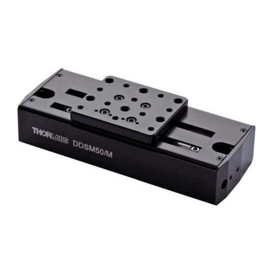
- Page 1 DDSM50 Direct Drive Translation Stage User Guide Original Instructions HA0335T...
-
Page 2: Table Of Contents
Chaper 7 Regulatory ....................19 7.1 Declarations Of Conformity ............19 7.1.1 For Customers in Europe ..............19 7.1.2 For Customers In The USA ..............19 7.2 CE Certification ................20 Chaper 8 Thorlabs Worldwide Contacts ..............21 Page 0 ETN014545-D02... -
Page 3: Chaper 1 Overview
This backlash-free operation coupled with high-resolution, closed-loop optical feedback ensures a minimal bidirectional repeatability of 1.5 µm. Along with the Thorlabs KBD101 controller and the Thorlabs APT software interface, it forms a truely plug and play system. The DDSM50 stage has been designed for easy XY configuration when used with the DDSMP1 XY adapter plate. -
Page 4: Chaper 2 Safety
DDSM50 Direct Drive Translation Stage Chapter 2 Safety 2.1 Safety Information For the continuing safety of the operators of this equipment, and the protection of the equipment itself, the operator should take note of the Warnings, Cautions and Notes throughout this handbook and, where visible, on the product itself. The following safety symbols may be used throughout the handbook and on the equipment itself. -
Page 5: General Warnings
Chapter 2 Safety 2.2 General Warnings Warning If this equipment is used in a manner not specified by the manufacturer, the protection provided by the equipment may be impaired. In particular, excessive moisture may impair operation. Spillage of fluid, such as sample solutions, should be avoided. If spillage does occur, clean up immediately using absorbant tissue. -
Page 6: Chaper 3 Installation
DDSM50 Direct Drive Translation Stage Chapter 3 Installation 3.1 Unpacking Note During handling or shipping, the moving platform must be constrained to avoid damage to the bearings. Retain the packing in which the unit was shipped, for use in future transportation. Caution Once removed from its packaging, the stage can be easily damaged by mishandling. -
Page 7: Mounting The Stage To The Work Surface
Chapter 3 Installation 3.2.3 Mounting the Stage to the Work Surface The DDSM50 stage is mounted to the working surface by two M6 x 25mm (1/4-20 x 1”) screws. The mounting holes are accessed from the top of the stage - see Fig. 3.1. Fig. -
Page 8: Mounting In Multi-Axis Configurations
DDSM50 Direct Drive Translation Stage 3.2.4 Mounting In Multi-Axis Configurations For dual-axis applications, two DDSM50 stages can be bolted together in an XY configuration by using the DDSMP1 attachment plate. Fig. 3.2 Typical XY Configuration Regarding Fig. 3.2 above: Caution During item (1), use the bolts supplied. -
Page 9: Electrical Connections
Chapter 3 Installation 3.3 Electrical Connections The stage must be driven by a Thorlabs KBD101 controller. Connect the motor flying lead to the MOTOR connector on the controller rear panel. Fig. 3.3 Electrical connections Pin out information for the connector on the motor lead is detailed below.. -
Page 10: Chaper 4 Operation
Chapter 4 Operation 4.1 General Caution The DDSM50 stage is designed to be driven by the Thorlabs KBD101 Brushless DC Motor K-Cube. For full compatibility, the controller should have Firmware version 1.0.1 or higher. The Firmware version is displayed in brackets, in the top right hand corner of the GUI panel for the Motor ActiveX control. -
Page 11: Using The Kinesis Software
- see the following pages for more information. 4.2 Using the Kinesis software 1) If it is not already running, start the Kinesis software - Start/Programs/Thorlabs/ Kinesis/Kinesis The software reads in the stage and controller information on boot up and the GUI panel shown below is displayed.. - Page 12 DDSM50 Direct Drive Translation Stage Note The MOTOR DRIVE connectors for each channel/axis contain an EEPROM, which stores the factory default settings for the set up parameters. When the stage is connected, these settings are loaded into the controller on start up, and are tuned for loads up to the 250 g (0.55 lb) maximum, at speeds up to 500 mm/s.
- Page 13 Chapter 4 Operation 4) After the parameter changes have been performed, click the ‘Persist Settings to Hardware’ box, then click ‘OK’. This will ensure that the same parameter settings will be loaded next time the unit is powered up - even in the absence of a PC. Table 4.1 DDSM100 Position Loop Parameter Adjustment Guidelines Load Range(g) Derivative...
-
Page 14: Using The Apt Software
DDSM50 Direct Drive Translation Stage 4.3 Using the APT Software 1) If it is not already running, start the APTUser utility - Start/Programs/Thorlabs/APT User/APT User The APT server reads in the stage and controller information on boot up and the GUI panel shown below is displayed. - Page 15 Chapter 4 Operation 2) Click the Settings button on the GUI to display the Settings panel, then select the ‘Advanced’ tab. Fig. 4.4 Advanced Control Loop Settings 3) Adjust the acceleration and PID settings to fine tune the control loop for your application see Table 4.1 and Table 4.2 for more information.
- Page 16 DDSM50 Direct Drive Translation Stage Table 4.2 DDSM50 Load vs Maximum acceleration recommendations Load (g) Approximate Max Acceleration (mm/s²) 5000 2400 1550 The values quoted above are the maximum values recommended to avoid over current errors. These values are a guideline only, and depending on the shape of the mass and the velocities used, these values may require further adjustment, particularly if the stages are mounted in an XY configuration.
-
Page 17: Position Error Messages
Chapter 4 Operation 4.4 Position Error Messages. Caution The maximum velocity at which the encoder can operate is approximately 3000 mm/sec. Above this speed, encoder pulses may be lost and, as a result, the position readout becomes incorrect. This renders normal operation impossible because phase commutation of the motor is also based on the encoder reading. -
Page 18: Chaper 5 Maintenance And Parts List
DDSM50 Direct Drive Translation Stage Chapter 5 Maintenance and Parts List 5.1 Maintenance Over time, the glass encoder scale can become dirty. To prevent errors due to lost encoder counts, the encoder scale should be cleaned periodically with isopropyl alcohol and a cotton bud as follows: 1) Move the top platform to one end of its travel. -
Page 19: Chaper 6 Specification
Chapter 6 Specification Chapter 6 Specification 6.1 Stage Specification Parameter Value Travel Range 50 mm (1.97") 500 mm/s Velocity (Max) Acceleration (Max) 5000 mm/s Bidirectional Repeatability ±1.5 µm Backlash N/A (No Leadscrew) Min Incremental Movement 500 nm Horizontal Load Capacity 0.9 kg (1.98 lbs) Absolute On-Axis Accuracy ±5.0 µm... -
Page 20: Motor Specification
DDSM50 Direct Drive Translation Stage Caution The maximum speed and acceleration values quoted can be safely achieved with the maximum load and a high duty cycle. However in this case, some heating of the stage may occur and dimensional stability of the stage may be affected. This could result in less than optimal repeatability and accuracy. -
Page 21: Chaper 7 Regulatory
Chapter 7 Regulatory Chapter 7 Regulatory 7.1 Declarations Of Conformity 7.1.1 For Customers in Europe See Section 7.2. 7.1.2 For Customers In The USA This equipment has been tested and found to comply with the limits for a Class A digital device, persuant to part 15 of the FCC rules. -
Page 22: Ce Certification
DDSM50 Direct Drive Translation Stage 7.2 CE Certification Page 20 ETN014545-D02... -
Page 23: Chaper 8 Thorlabs Worldwide Contacts
Waste treatment is your own responsibility. "End of life" units must be returned to Thorlabs or handed to a company specializing in waste recovery. Do not dispose of the unit in a litter bin or at a public waste disposal site. - Page 24 www.thorlabs.com...
Need help?
Do you have a question about the DDSM50 Series and is the answer not in the manual?
Questions and answers