Table of Contents
Advertisement
Quick Links
Advertisement
Table of Contents

Related Manuals for THORLABS TBD001


Summary of Contents for THORLABS TBD001
- Page 1 TBD001 T-Cube Brushless DC Servo Driver User Guide Original Instructions...
-
Page 2: Table Of Contents
Contents Chapter 1 Safety ..................... 4 1.1 Safety Information .................. 4 1.2 General Warnings .................. 4 Chapter 2 Overview and Setup ..............5 2.1 Introduction ..................... 5 2.2 PC Software Overview ................7 2.2.1 Introduction ......................7 2.2.2 Kinesis Server ....................7 2.2.3 Software Upgrades ..................... - Page 3 6.4 Troubleshooting and Restoring Default Parameters ......48 Appendices Appendix A Rear Panel Connector Pinout Details ........49 Appendix B Preventive Maintenance ............50 Appendix C Specifications ................51 Appendix D Regulatory ................52 Appendix E Thorlabs Worldwide Contacts ..........55...
-
Page 4: Chapter 1 Safety
To minimize the possibility of this happening it is strongly recommended that any such modes that result in prolonged unresponsiveness be disabled before the software is run. Please consult your system administrator or contact Thorlabs technical support for more details. -
Page 5: Chapter 2 Overview And Setup
Chapter 2 Overview and Setup 2.1 Introduction The TBD001 Brushless DC Motor T-Cubes are ideal for motion control applications demanding high speed (100s of mm/s) and high encoder resolution (<100 nm) operation. These single channel drivers offer high-precision motion control in a wide range of applications, and in particular when used along with our DDSM100 fast translation stage where speeds of up to 500 mm/sec can be achieved. - Page 6 Chapter 2 Operation of the TBD001 brushless DC motor unit is fully configurable (parameterized) with key settings (e.g. PID settings, min and max position values, and joystick response) exposed through the associated graphical interface panels. PID control loop values can be adjusted for a particular application, minimum and maximum position values can be entered to suit different stages as required, and the response of the key pad joystick can be adjusted for speed or precision.
-
Page 7: Pc Software Overview
Brushless DC Servo Driver T-Cube 2.2 PC Software Overview 2.2.1 Introduction The T-Cube range of controllers share many of the benefits. These include USB connectivity (allowing multiple units to be used together on a single PC), fully featured Graphical User Interface (GUI) panels, and extensive software function libraries for custom application development. - Page 8 Chapter 2 Consider the control supplied for the TBD001 Brushless DC Servo driver unit. This Control provides a complete user graphical instrument panel to allow the motor unit to be manually operated, as well as a complete set of software functions (often called methods) to allow all parameters to be set and motor operations to be automated by a client application.
-
Page 9: Software Upgrades
Kinesis Controls collection. This is available either by pressing the F1 key when running the Kinesis server, or via the Start menu, Start\Programs\Thorlabs\Kinesis\Kinesis Help. 2.2.3 Software Upgrades Thorlabs operate a policy of continuous product development and may issue software upgrades as necessary. -
Page 10: Chapter 3 Getting Started
To minimize the possibility of this happening it is strongly recommended that any such modes that result in prolonged unresponsiveness be disabled before the software is run. Please consult your system administrator or contact Thorlabs technical support for more details. Caution Some PCs may have been configured to restrict the users ability to load software, and on these systems the software may not install/run. -
Page 11: Mechanical Installation
For multiple cube systems, a USB controller hub (TCH002) is available - see Section 3.3.2. for further details. Full instructions on the fitting and use of the controller hub are contained in the associated handbook, available at www.thorlabs.com. Caution When siting the unit, it should be positioned so as not to impede the operation of the control panel buttons. -
Page 12: Removing The Baseplate
Chapter 3 3.2.3 Removing the Baseplate The baseplate must be removed before the rubber feet (supplied) can be fitted, or the unit is connected to the USB controller hub.. Detail A Detail B Baseplate attachment screws Baseplate removed and rubber feet fitted Fig. -
Page 13: Electrical Installation
The TCH002 USB Controller Hub provides power distribution for up to six T-Cubes, and requires only a single power connection. Further details are contained in the associated handbook available from www.thorlabs.com. Warning DO NOT PLUG A POWERED UP T-CUBE INTO THE TCH002 USB CONTROLLER HUB. -
Page 14: Connect The Hardware
2) Using the front panel connector as shown above, connect the unit to a regulated DC power supply of 15 V, 2A. Thorlabs offers a compact, multi-way power supply unit (TPS008), allowing up to four Brushless Driver T-Cubes to be powered from a single mains outlet. A single way wall plug supply (TPS003) for powering a single Driver T-Cube is also available. - Page 15 Brushless DC Servo Driver T-Cube 7) Wait until the Enable LED stop flashing (~3s). This indicates that phase initialisation is complete. Note 3-phase brushless DC motors are commutated electronically, i.e. the controller drives the coils with a precisely controlled waveform, that depends on the position of the rotor (or, with linear motors, the position of the coil housing).
-
Page 16: Select The Stage Type
Kinesis software) - see Section 6.3.3. 1) Ensure that the device is connected to the PC and powered up. 2) Run the Kinesis software - Start/All Programs/Thorlabs/Kinesis/Kinesis. 3) The 'Actuator/Startup Settings ' window is displayed. -
Page 17: Chapter 4 Standalone Operation
4.1 Introduction The Brushless DC Driver T-Cube has been designed specifically to operate with the range of Thorlabs Brushless DC motorised opto-mechanical products. The unit offers a fully featured motion control capability including velocity profile settings, limit switch handling, homing sequences and, for more advanced operation, adjustment of PID settings, allowing support for many different actuator configurations. -
Page 18: Joystick Operation
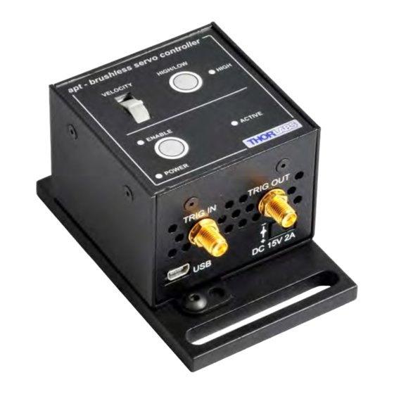
Chapter 4 Active LED - The Active LED flashes when the Ident button is pressed in the GUI panel. It can also be lit when the motor is moving. - see Section 6.3.4. for further details. POWER LED - Lit when power is applied to the unit. 4.3 Joystick Operation The VELOCITY joystick is a sprung potentiometer, such that when released it returns to its central position. -
Page 19: Trigger In
Brushless DC Servo Driver T-Cube 4.5.1 Trigger In TTL Buffer Connector Protection Fig. 4.3 TRIG IN Connection Detail The TRIG IN input contains a pull up resistor to an internal +5V supply, allowing it to be operated by passive devices (e.g. a switch or relay contact) as well as standard logic outputs. -
Page 20: Triggering Latency
Chapter 4 4.5.3 Triggering Latency The detection of whether a trigger condition has occurred is carried out periodically at 102 µs intervals. As a result, there is a maximum 102 µs delay between the condition occurring and the trigger output being updated. The following timing diagram illustrates this latency: Trigger condition occurs time... -
Page 21: Chapter 5 Tutorial
However, if the output is disabled (with the driver connected and monitoring the position) and the stage is moved manually at high speeds, it is possible to exceed this limit. If the TBD001 driver is subsequently used again to move the stage, the incorrect encoder reading will cause incorrect operation, often resulting in sudden uncontrolled moves. -
Page 22: Using The Kinesis Software
The Software should be installed (Section 3.1.) and the power up procedure performed (Section 3.3.) before software operation can be verified. 1) Run the Kinesis software - Start/All Programs/Thorlabs/Kinesis/Kinesis. 1) Notice how the DDSM100 stage type, selected at start up, is displayed in the window. -
Page 23: Homing Motors
Brushless DC Servo Driver T-Cube 5.4 Homing Motors The need for homing comes from the fact that on power up the motor (stage) is at a random position, so the value of the position counter is meaningless. Homing involves moving the motor to a known reference marker and resetting the position counter to the associated absolute value. -
Page 24: Changing Motor Parameters And Moving To An Absolute Position
Chapter 5 5.5 Changing Motor Parameters and Moving to an Absolute Position Absolute moves are measured in real world units (e.g. millimetres), relative to the Home position. Moves are performed using a trapezoidal velocity profile (see Section 6.3.5.). The velocity settings relate to the maximum velocities at which a move is performed, and the acceleration at which the motor speeds up from zero to maximum velocity. -
Page 25: Jogging 2
Brushless DC Servo Driver T-Cube 5.6 Jogging During PC operation, the motor actuators are jogged using the GUI panel arrow keys. There are two jogging modes available, ‘Single Step’ and ‘Continuous’. In ‘Single Step’ mode, the motor moves by the step size specified in the Step Distance parameter. -
Page 26: Setting Move Sequences
Chapter 5 5.7 Setting Move Sequences The Kinesis software allows move sequences to be programmed, allowing several positions to be visited without user intervention. For more details and instructions on setting move sequences, please see the Kinesis Helpfile. 5.8 Changing and Saving Parameter Settings During operation, certain settings (e.g. -
Page 27: Chapter 6 Software Reference
Chapter 6 Software Reference 6.1 Introduction This chapter gives an explanation of the parameters and settings accessed from the Kinesis software running on a PC. 6.2 GUI Panel The following screen shot shows the graphical user interface (GUI) displayed when accessing the Brushless DC driver using the Kinesis software. - Page 28 Chapter 6 These settings can be adjusted as described previously, or by clicking the Settings button to display the settings window, see Section 6.3.2. Jog Controls - used to increment or decrement the motor position. The controls comprise a bar graph and a set of jog arrows.
-
Page 29: Keyboard Shortcuts
Brushless DC Servo Driver T-Cube Stop - halts the movement of the motor. Lower Display - Shows the present state of the motor, e.g. Idle, Moving, Moving EXT or Homing. Also shows the part number of the associated actuator or stage. 6.2.1 Keyboard Shortcuts Certain functionality can also be accessed via PC keyboard shortcuts as follows: Jog Forwards... -
Page 30: Settings Panel
Chapter 6 6.3 Settings Panel When the 'Settings' button on the GUI panel is clicked, the 'Settings' window is displayed. This panel allows motor operation parameters such as move/jog velocities, and stage/axis information to be modified. There are two settings tabs, ‘Current Device Setting’ and Device Startup Settings’. The Current Device settings option shows the settings currently active in the device. -
Page 31: Moves/Jogs Tab
Brushless DC Servo Driver T-Cube 6.3.2 Moves/Jogs tab Fig. 6.2 Move/Jog Settings Display Units By default, the unit will display position in real world units (mm or degrees). If required, the units can be changed to so that the display shows other positional units (cm, µm, µrad etc). - Page 32 Chapter 6 Jogs are initiated by using the ‘Jog’ keys on the GUI panel (see Section 5.6.), or the Jog Buttons on the front panel of the unit. Step Size - The distance to move when a jog command is initiated. The step size is specified in real world units (mm or degrees dependent upon the stage).
- Page 33 Brushless DC Servo Driver T-Cube Maximum Velocity - the maximum velocity at which to perform a move. Note Under certain velocity parameter and move distance conditions, the maximum velocity may never be reached (i.e. the move comprises an acceleration and deceleration phase only). The limits for the max velocity or acceleration parameters are dependent on the stage being driven.
-
Page 34: Stage/Axis Tab
They need to be set accordingly such that a particular stage is driven properly by the system. For Thorlabs stages, the Kinesis server will automatically apply suitable defaults for the parameters on this tab during boot up of the software. - Page 35 Brushless DC Servo Driver T-Cube Stage Axis Settings These parameters are read automatically when the actuator/stage was associated at start up - see Section 3.5. These settings are provided for information only and cannot be adjusted. They should always be quoted when requesting technical support. Actuator Name - The name (part number) of the stage or actuator connected.
-
Page 36: Advanced Settingstab
Chapter 6 Hardware Limit Switches Note The minimum velocity and acceleration/deceleration parameters for a home move are taken from the existing move velocity profile parameters. The operation of the limit switches is inherent in the design of the associated stage or actuator. - Page 37 Brushless DC Servo Driver T-Cube Position Loop Settings The motion processors within the TBD001 driver uses a position control loop to determine the motor command output. The purpose of the position loop is to match the actual motor position and the demanded position. This is achieved by comparing the demanded position with the actual encoder position to create a position error, which is then passed through a digital PID-type filter.
- Page 38 Chapter 6 Derivative Recalculation Time – Time over which derivative is calculated. Under normal circumstances, the derivative term of the PID loop is recalculated at every servo cycle. However, it may be desirable to increase the sampling rate to a higher value, in order to increase stability.
- Page 39 Brushless DC Servo Driver T-Cube Current Loop Settings The motion processor within the TBD driver uses digital current control as a technique to control the current through each phase winding of the motors. In this way, response times are improved and motor efficiency is increased. This is achieved by comparing the required current with the actual current to create a current error, which is then passed through a digital PI-type filter.
- Page 40 Chapter 6 Current Loop Settings (Settled) The following parameters are designed to assist in maintaining stable operation and redusing noise at the demanded position. They allow the system to be tuned such that errors caused by external vibration and manual handling (e.g. loading of samples) are minimized, and are applicable only when the stage is settled, i.e.
- Page 41 Brushless DC Servo Driver T-Cube Excess Energy Limit – When the current output of the drive exceeds the limit set in the Current Limit parameter, accumulation of the excess current energy begins. The Energy Limit parameter specifies a limit for this accumulated energy, as a percentage of the factory set default maximum, in the range 0% to 100%.
-
Page 42: Advanced - Misc. Tab
Chapter 6 irrespective of the actual position attained, and the settle parameters described above will be ignored. The processor also provides a 'tracking window' which is used to monitor servo performance outside the context of motion error. The tracking window is a programmable position error limit within which the axis must remain, but unlike the Position Error Limit parameter set in the Position Loop Settings group, the axis is not stopped if it moves outside the specified tracking window. - Page 43 Brushless DC Servo Driver T-Cube given moment. During a motion profile, these values will change continuously. Once the move is complete, these parameters will then remain unchanged until the next move begins. The specific move profile created by the system depends on several factors, such as the profile mode and profile parameters presently selected, and other conditions such as whether a motion stop has been requested.
- Page 44 Chapter 6 Example A - acceleration D - deceleration V - velocity J - jerk Time Fig. 6.8 Typical S-Curve Profile The figure above shows a typical S-curve profile. In segment (1), the S-curve profile drives the axis at the specified jerk (J) until the maximum acceleration (A) is reached. The axis continues to accelerate linearly (jerk = 0) through segment (2) .
- Page 45 Brushless DC Servo Driver T-Cube Drive Array Velocities These parameters relate to the velocity for moves initiated by the DRIVE bar graph. Each specifies a velocity to apply when the associated bar is clicked. These settings are applicable in either direction of pot deflection, i.e. 4 possible velocity settings in the forward or reverse motion directions.
- Page 46 Chapter 6 Relative Move (Trig Fall) – as above, but the relative move is initiated on receipt of a falling edge signal. Absolute Move (Trig Rise) – an absolute move (specified using the latest MoveAbsolute or MoveAbsoluteEx method settings) is initiated on the specified channel when a rising edge input signal is received on the TRIG IN connector.
-
Page 47: Triggering Latency 4
Brushless DC Servo Driver T-Cube At Maximum Velocity (High) – The output trigger goes high (5V) when the stage reaches max velocity (as set using the SetVelParams method). At Maximum Velocity (Low) – The output trigger goes low (0V) when the stage reaches max velocity (as set using the SetVelParams method). -
Page 48: Troubleshooting And Restoring Default Parameters
Chapter 6 6.4 Troubleshooting and Restoring Default Parameters Caution The PID and other closed loop parameters must be set according to the stage or actuator type associated with the driver, the load being positioned and the speed/duty cycle of operation. Default values have already been optimized and stored within the stage, and these are loaded into the driver on power up. -
Page 49: Appendix A Rear Panel Connector Pinout Details
Quadrature X+/-: Differential quadrature pulses of the encoder Encoder Index I -/+: The differential Index pulse used for homing Limit -/+: Positive and negative limit switch signals Stage ID: Unique Thorlabs communication interface signal used to identify the stage connected. Fig. A.1... -
Page 50: Appendix B Preventive Maintenance
The equipment contains no user servicable parts. There is a risk of electrical shock if the equipment is operated with the covers removed. Only personnel authorized by Thorlabs Ltd and trained in the maintenance of this equipment should remove its covers or attempt any repairs or adjustments. -
Page 51: Appendix C Specifications
Appendix C Specifications C.1 Specifications Parameter Value Drive Connector 15-Pin D-Type, Female (Motor Phase Outputs, Stage ID Input) Peak Current Output PWM Frequency 40 kHz Operating Modes Position, Velocity Control Algorithm 16-bit Digital PID Servo Loop with Velocity and Acceleration Feedforward Velocity Profile Trapezoidal/S-Curve Position Count... -
Page 52: Appendix D Regulatory
Appendix D Regulatory D.1 Declarations Of Conformity D.1.1 For Customers in Europe This equipment has been tested and found to comply with the EC Directives 89/336/EEC ‘EMC Directive’ and 73/23/EEC ‘Low Voltage Directive’ as amended by 93/68/EEC. Compliance was demonstrated by conformance to the following specifications which have been listed in the Official Journal of the European Communities: Safety EN61010: 2001 Installation Category II, Polution Degree II. - Page 53 • left over parts of units disassembled by the user (PCB's, housings etc.). If you wish to return a unit for waste recovery, please contact Thorlabs or your nearest dealer for further information. D.2.2 Waste treatment on your own responsibility If you do not return an "end of life"...
- Page 54 Appendix D D.3 CE Certificate HA0265T Rev DK Sept 2015...
-
Page 55: Appendix E Thorlabs Worldwide Contacts
Appendix E Thorlabs Worldwide Contacts For technical support or sales inquiries, please visit us at www.thorlabs.com/contact for our most up-to-date contact information. USA, Canada, and South America UK and Ireland Thorlabs, Inc. Thorlabs Ltd. sales.uk@thorlabs.com sales@thorlabs.com techsupport@thorlabs.com techsupport.uk@thorlabs.com Europe Scandinavia... - Page 56 www.thorlabs.com...
Need help?
Do you have a question about the TBD001 and is the answer not in the manual?
Questions and answers