Table of Contents
Advertisement
Advertisement
Table of Contents

Subscribe to Our Youtube Channel
Related Manuals for Dahua IP Villa System


Summary of Contents for Dahua IP Villa System
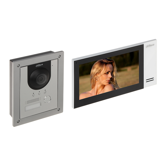
- Page 1 IP Villa System Quick Start Guide V1.0.0...
-
Page 2: Foreword
Foreword General This document mainly introduces structure, installation process, debugging, and verification process of the IP villa system. Safety Instructions The following categorized signal words with defined meaning might appear in the manual. Signal Words Meaning Indicates a potential risk which, if not avoided, could result in property CAUTION damage, data loss, lower performance, or unpredictable result. - Page 3 If there is any uncertainty or controversy, please refer to our final explanation. Foreword...
-
Page 4: Important Safeguards And Warnings
Important Safeguards and Warnings The following description is the correct application method of the device. Read the manual carefully before use, in order to prevent danger and property loss. Strictly conform to the manual during application and keep it properly after reading. Operating Requirement Do not place and install the device in an area exposed to direct sunlight or near heat ... -
Page 5: Table Of Contents
Table of Contents Foreword ..............................I Important Safeguards and Warnings ....................III 1 Overview ..............................1 Outdoor Station (VTO) Front Panel ....................1 Outdoor Station (VTO) Rear Panel ....................2 Indoor Monitor (VTH) Front Panel ....................2 Indoor Monitor (VTH) Rear Panel ....................3 Network Diagram .......................... -
Page 6: Outdoor Station (Vto) Front Panel
Overview Outdoor Station (VTO) Front Panel VTO front panel Table 1-1 Front panel description Name Description Inputs audio. Camera Monitors door area. Indicator After you have started a call, this indicator will be on. Indicator During the communication, this indicator will be on. Indicator When the door is unlocked, this indicator will be on. -
Page 7: Indoor Monitor (Vth) Front Panel
Outdoor Station (VTO) Rear Panel Outdoor station (VTO) rear panel Table 1-2 Rear panel description Name Description The outdoor station (VTO) would make alarm sound if it is being Tamper removed from the wall by force, and the alarm will also be sent to the switch management center. -
Page 8: Indoor Monitor (Vth) Rear Panel
Table 1-3 Front panel button Icon or Name Description Silkscreen Tap this key to call the call center in case of emergency. Menu Tap this key to return to main menu. Press this key to answer the call. During talk, press this key to hang up. Call During monitoring, press this key to speak to unit outdoor station (VTO), villa outdoor station (VTO) and fence station. -
Page 9: Overview
Network Diagram Network diagram Overview... -
Page 10: Outdoor Station (Vto) Rear Panel
Installation and Configuration Do not install the device in environment with condensation, high temperature, stained, dusty, chemically corrosive and direct sunshine. In case of abnormality after power on, pull out network cable and cut off power supply at once. -
Page 11: Flush Mount
Name M3×8 Screws Waterproof silica gel pad Expansion screw Wall Hammer four expansion screws into the wall. Install the waterproof silica gel pad on the surface mount box from the back of the surface mount box. Put four waterproof rings on four ST4×25 self-tapping screws. Install the mounting box on the wall by screwing the four ST4×25 self-tapping screws into the expansion screws. -
Page 12: Electric Lock And Magnetic Door Lock
Fix the outdoor station (VTO) to the front box by screwing two M3×8 screws into the outdoor station (VTO) from the bottom of the front box. Put the front box (with VTO) into the rear box. Put waterproof rings to the M3×8 screws. Screw four M3×8 screws (with waterproof ring) into the front box. -
Page 13: Indoor Monitor (Vth) Installation
Indoor Monitor (VTH) Installation 2.3.1 Installing with 86 Box Install the device with 86 box, which is suitable for all types of devices. Take "VTH1560B/BW" for example. Embed 86 box into a wall at a proper height. Fix installation bracket on the 86 box with screws. Hang the indoor monitor (VTH) on the installation bracket. -
Page 14: Configuration
Installing with desktop bracket Configuration Before configuration, check whether the following work has been completed or not. Check whether there is short circuit or open circuit. Power on the device only after the circuit is normal. IP addresses and No. of every outdoor station (VTO) and indoor monitor (VTH) have been ... - Page 15 Device initialization Enter password, confirm Pwd, and email, and then press OK. The indoor monitor (VTH) is initialized. 2.4.1.2 Quick Configuration After the indoor monitor (VTH) is initialized, the message Do you want to do quick configuration? appears. See Figure 2-8. Select quick configuration or not Tap OK.
- Page 16 Tap Cancel, you need to configure parameters for the indoor monitor (VTH) according to your needs. All intercoms displayed Select an uninitialized device. The Device Init interface is displayed. See Figure 2-10. Initialization of all intercoms must be done on the indoor monitor (VTH); otherwise ...
- Page 17 After intercoms need initialization have been initialized, click Next on Figure 2-9, the configuration interface will be displayed. See Figure 2-11. Configuration interface Tap Edit behind each device to do configurations. Configure main VTH and Sub-VTH. There must be only one main VTH and one or ...
- Page 18 The VTH configuration is completed. Configure Main outdoor stations (VTO) and sub outdoor stations (VTO). There must be only one main outdoor stations (VTO) and one or more sub outdoor stations (VTO). If there are no sub outdoor stations (VTO), then you do not need to do sub outdoor stations (VTO) configurations.
-
Page 19: Outdoor Stations (Vto) Settings
Making the configuration effective Click One-key Config. The VTO configuration is completed. 2.4.2 Outdoor Stations (VTO) Settings Indoor stations (VTH) and outdoor stations (VTO) are always used together so you need to configure outdoor stations (VTO) parameters in advance to ensure the communication between indoor stations (VTH) and outdoor stations (VTO). -
Page 20: Watching Monitoring Videos At Indoor Monitors (Vth)
Calling VTHs from VTOs 2.5.2 Watching Monitoring Videos at Indoor Monitors (VTH) You can watch monitor places where outdoor station (VTO), fence station or IPC are installed. Here outdoor station (VTO) will be taken as an example. Select Monitor > Door. The Door interface is displayed. - Page 21 Monitoring video Installation and Configuration...
-
Page 22: Connecting Mobile Phone App
Connecting Mobile Phone App You can download the mobile phone app, and then add your villa outdoor monitor (VTO) to the app. When someone is calling you from the villa outdoor monitor (VTO), there will be push message on your phone, and you can talk to the visitor or unlock the door remotely on your phone. - Page 23 Name your target outdoor monitor (VTO), and then tap the sign. The mobile phone starts to scan. Log in to the web interface of the outdoor monitor (VTO) you need to add, and then select Network. The P2P interface is displayed. See Figure 3-4. For VTO3211D, select Household Setting >...
- Page 24 Live Tap Alarm Manager > Subscribe, and then subscribe the outdoor monitor (VTO) you need. See Figure 3-6. Subscribe When someone is calling you from the subscribed villa outdoor monitor (VTO), there will be push message on your phone. See Figure 3-7. Connecting Mobile Phone App...
- Page 25 Push Connecting Mobile Phone App...
-
Page 26: Cybersecurity Recommendations
Cybersecurity Recommendations Cybersecurity is more than just a buzzword: it’s something that pertains to every device that is connected to the internet. IP video surveillance is not immune to cyber risks, but taking basic steps toward protecting and strengthening networks and networked appliances will make them less susceptible to attacks. - Page 27 Change Default HTTP and Other Service Ports We suggest you to change default HTTP and other service ports into any set of numbers between 1024~65535, reducing the risk of outsiders being able to guess which ports you are using. Enable HTTPS We suggest you to enable HTTPS, so that you visit web service through a secure communication channel.
- Page 28 The network should be partitioned and isolated according to the actual network needs. If there are no communication requirements between two sub networks, it is suggested to use VLAN, network GAP and other technologies to partition the network, so as to achieve the network isolation effect. Establish the 802.1x access authentication system to reduce the risk of unauthorized ...
Need help?
Do you have a question about the IP Villa System and is the answer not in the manual?
Questions and answers