Sign In
Upload
Download
Add to my manuals
Delete from my manuals
Share
URL of this page:
HTML Link:
Bookmark this page
Add
Manual will be automatically added to "My Manuals"
Print this page
×
Bookmark added
×
Added to my manuals
Manuals
Brands
Dahua Manuals
Intercom System
VTO7541G
Quick start manual
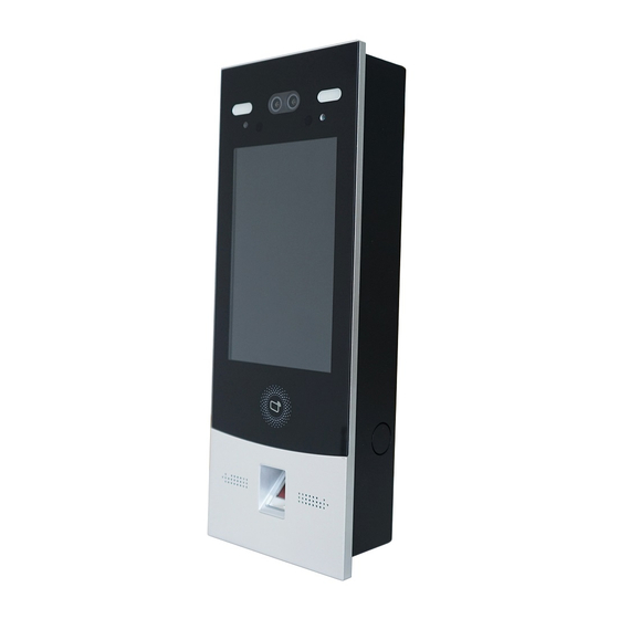
Dahua VTO7541G Quick Start Manual
Digital face recognition outdoor station
Hide thumbs
1
2
3
4
Table Of Contents
5
6
7
8
9
10
11
12
13
14
15
16
17
18
19
20
21
22
23
24
25
26
27
28
29
30
31
page
of
31
Go
/
31
Contents
Table of Contents
Bookmarks
Advertisement
Quick Links
1
Connecting Cable
2
Installation
3
Configuration Process
4
Configuration
5
User Registration
Download this manual
Digital Face Recognition
Outdoor Station
Quick Start Guide
V1.0.1
Table of
Contents
Previous
Page
Next
Page
1
2
3
4
5
Advertisement
Need help?
Do you have a question about the VTO7541G and is the answer not in the manual?
Ask a question
Questions and answers
Related Manuals for Dahua VTO7541G
Intercom System Dahua VTO7521G Quick Start Manual
Digital face recognition outdoor station (31 pages)
Intercom System Dahua VTO6 User Manual
Ip door stations (25 pages)
Intercom System Dahua Villa VTO Series Quick Start Manual
(43 pages)
Intercom System Dahua VTO2000A Connection Manual
How to connect vto and vth (16 pages)
Intercom System Dahua VTO2000A-2 User Manual
2-wire (36 pages)
Intercom System Dahua VTO2111D-WP User Manual
Digital villa vto (vto2 series) (40 pages)
Intercom System Dahua VTO2111D-WP Setup Instruction
(28 pages)
Intercom System Dahua VTO Series Quick Start Manual
(39 pages)
Intercom System Dahua VTO2101E-P Quick Start Manual
Villa door station (36 pages)
Intercom System Dahua VTO4202F-P Series Quick Start Manual
Modular vto (36 pages)
Intercom System Dahua VTO4202F-MK Quick Start Manual
Modular door station (27 pages)
Intercom System Dahua VTO2202F Quick Start Manual
(29 pages)
Intercom System Dahua KTP02 User Manual
(32 pages)
Intercom System Dahua DHI-VTO2202F-P Quick Start Manual
(28 pages)
Intercom System Dahua DHI-VTO3211D-P4-S1 User Manual
(35 pages)
Intercom System Dahua VTO4202FB-P-S2 Quick Start Manual
Modular door station (27 pages)
This manual is also suitable for:
Vto7521g
Save PDF
Print
Rename the bookmark
Delete bookmark?
Delete from my manuals?
Login
Sign In
OR
Sign in with Facebook
Sign in with Google
Upload manual
Upload from disk
Upload from URL


Need help?
Do you have a question about the VTO7541G and is the answer not in the manual?
Questions and answers