Table of Contents
Advertisement
Advertisement
Table of Contents

Related Manuals for Dahua DHI-VTO4202F Series


Summary of Contents for Dahua DHI-VTO4202F Series
- Page 1 Intercom Modular Outdoor Station DHI-VTO4202F Series User’s Manual V1.0.2...
-
Page 2: Foreword
General This manual offers reference material and general information about the basic operation, maintenance, and troubleshooting for a Dahua security device. Read, follow, and retain the following safety instructions. Heed all warnings on the unit and in the operating instructions before operating the unit. - Page 3 Guide. Contact the customer service for the latest program and supplementary documentation. Video loss is inherent to all digital surveillance and recording devices; therefore, Dahua cannot be held liable for any damage that results from missing video information. To minimize the occurrence of lost digital information, Dahua recommends multiple, redundant recording systems, and adoption of backup procedures for all data.
-
Page 4: Important Safeguards And Warnings
Important Safeguards and Warnings This chapter describes the contents covering proper handling of the device, hazard prevention, and prevention of property damage. Read these contents carefully before using the device, comply with them when using, and keep it for future reference. Installation and Maintenance Professionals Requirements All installation and maintenance professionals must have adequate qualifications or ... - Page 5 have the same characteristics as the original parts. Unauthorized parts may cause fire, electrical shock, or other hazards. Dahua is not liable for any damage or harm caused by unauthorized modifications or repairs. Perform safety checks after completion of service or repairs to the unit.
- Page 6 Use attachments and accessories only specified by the manufacturer. Any change or modification of the equipment, not expressly approved by Dahua, could void the warranty. Internal and external ground connection should be stable. Do not supply power via the Ethernet connection (PoE) when power is already supplied ...
-
Page 7: Cybersecurity Recommendations
Cybersecurity Recommendations Mandatory actions to be taken towards cybersecurity Change Passwords and Use Strong Passwords The number one reason systems are “hacked” is due to having weak or default passwords. It is recommended to change default passwords immediately and choose a strong password whenever possible. - Page 8 Forward Only Ports You Need Forward only the HTTP and TCP ports that are requited. Do not forward a wide range of numbers to the device. Do not DMZ the device's IP address. Do not forward any ports for individual cameras if they are all connected to a recorder on site.
- Page 9 Secure Auditing Check online users regularly to ensure unauthorized accounts are not logged in to a device. Check the equipment log to access the IP addresses used to login to devices and their key operations. VIII...
-
Page 10: Table Of Contents
Table of Contents Foreword ................................I Important Safeguards and Warnings ......................III Cybersecurity Recommendations ......................VI 1 Overview............................... 1 2 Intercom Modules ............................2 Camera Module ..................................2 Status Light Panel ..................................4 Five-button Call Panel ................................5 Keypad Module ..................................6 IC Card Reader .................................. - Page 11 8 Network ..............................35 Basic ......................................35 8.1.1 TCP/IP ................................... 35 8.1.2 Port ....................................36 8.1.3 P2P ....................................36 UPnP ......................................36 8.2.1 Enabling UPnP Services ............................37 8.2.2 Adding UPnP Services ............................37 SIP Server ....................................38 Firewall ..................................... 39 9 Log Management ............................40...
-
Page 12: Overview
Overview The Dahua Intercom Modular System is a complete intercom solution that offers full customization of the entire system. This intercom system starts with a 2 MP outdoor video intercom module that offers a wide-angle view lens, high-resolution images even in dark environments, and two-way talk. Then, add optional modules that offer door access capability (card reader, fingerprint reader, and keypad), call buttons, information text display, and status light indicators. -
Page 13: Intercom Modules
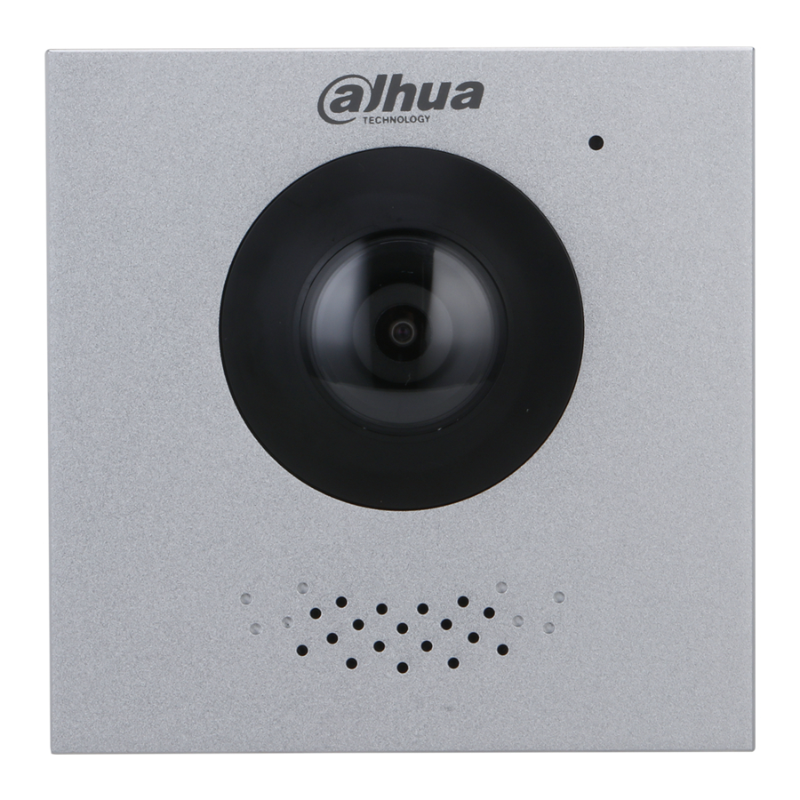
Intercom Modules Camera Module Front Panel Name Description Inputs audio. Camera Monitors door area. Speaker Outputs audio. Rear Panel... - Page 14 Name Description The VTO issues an alarm sound if it is removed from the Tamper Switch wall by force, and sends the alarm to the management center. Connect to power supply, electric control lock, solenoid Ports lock, and exit button. Ethernet Port Connects unit to Ethernet network.
-
Page 15: Status Light Panel
Status Light Panel Front Panel Description Call indicator Talk indicator Unlock indicator Rear Panel Description Cascade input Cascade output... -
Page 16: Five-Button Call Panel
Five-button Call Panel Name Description User directory Add a physical name cards to the slots. Call a VTH Monitor or the management center. Call buttons Requires programming in the VTO interface. Rear Panel Description Cascade input Cascade output... -
Page 17: Keypad Module
Keypad Module Description Selection Numbers Place call Call management center Rear Panel Description Cascade input Cascade output... -
Page 18: Ic Card Reader
IC Card Reader Rear Panel Description Cascade input Cascade output... -
Page 19: Fingerprint Reader
Fingerprint Reader Rear Panel Description Cascade input Cascade output... -
Page 20: Information Text Display
Information Text Display Rear Panel Description Cascade input Cascade output Blank Module This module is used to cover extra space if no other functional modules are needed. -
Page 21: Making Cascade Connections
Making Cascade Connections The cascade connections are required for all modules. The Outdoor Video Intercom Panel (the left-most panel above) is the only required module and is the starting point for the cascade connections. Note: The VTO connection must be made to an Input port. •... -
Page 22: Initializing The Vto
Initializing the VTO For first-time login or after resetting the VTO, initialize the device on the web interface. Power on the VTO. Enter the default IP address (192.168.1.108) of the VTO in the browser address bar. Make sure that the IP address of your PC is in the same network segment as the VTO. Device initialization Enter and confirm the password, and then click Next. -
Page 23: Login And Reset The Password
Login and Reset the Password Login Before login, make sure that the PC is in the same network segment as the VTO. Go to the IP address of the VTO in the browser. For first-time login, enter the default IP. If you have multiple VTOs, we recommend changing the default IP address (Network >... -
Page 24: Resetting The Password
Resetting the Password Click Forgot Password? and then click Next. Reset the password (2/3) Scan the QR code to receive a get a string of numbers and letters. Send the string to the following email address: support_gpwd@htmicrochip.com. The security code is sent to the email address configured during initialization. Enter the security code in the input box, and then click Next. -
Page 25: Main Interface
Main Interface Main interface Table 5-1 Main interface introduction Function Description : Change the password and your email address. : Return to the main interface. : Log out, restart the VTO or restore the VTO to factory settings. General function If you restore the VTO to factory settings, the unit deletes all data except the external storage. -
Page 26: Local Settings
Local Settings This chapter introduces the detailed configuration of the VTO. Basic Select Local Settings > Basic. Basic Configure the parameters. Table 6-1 Basic parameter description Parameter Description Device Type Select Villa Station or Small Apartment. Center Call No. The default phone number for the management center is 888888. Device Name This name appears when other devices are monitoring this VTO. -
Page 27: Video And Audio
Parameter Description SD Used Capacity Format Auto Capture VTO takes two snapshots when the door is unlocked and saves the (Unlock) images to the SD card. Takes a snapshot and saves to the SD card of the VTO when the VTO Auto Capture (Calling) receives a call. - Page 28 Configure the parameters to take effect as you make changes. Table 6-2 Video parameter description Parameter Description Select a resolution appropriate for your needs: 1080P: 1920 × 1080. 720P: 1280 × 720. Video Format WVGA: 800 × 480. QVGA: 320 × 240. Main/Sub D1: 720 ×...
-
Page 29: Access Control Settings
Access Control Settings This section details the configuration of the two locks connected to the lock ports or to the RS-485 port on the VTO. 6.3.1 Local Select Local Settings > Access Control Settings > Local. Local Configure the parameters. Table 6-3 Local access control parameter description Parameter Description... -
Page 30: Rs-485
Click Save. 6.3.2 RS-485 Select Local Settings > Access Control Settings > RS-485, and then configure the parameters of the lock connected through the RS-485 port. See Table 6-3 for parameter description. Lock connected through the RS-485 port 6.3.3 Password Management Add a username and password used to unlock the door. -
Page 31: System
System Configure time parameters, NTP server, and more. Select Local Settings > System. System Configure the parameters. Table 6-4 System parameter description Parameter Description Date Format Select a format as needed. Time Format Changing system time may cause issues when searching video. Turn off video System Time recording and auto snapshot before changing the time. -
Page 32: Security
Click Save. Security Configure functions that involve device security. Select Local Settings > Security. Security Configure the parameters. Table 6-5 Security parameter description Parameter Description Enable the use of CGI commands. CGI Enable It is recommended to disable this function or the VTO might be exposed to security risks and data leakage. -
Page 33: Wiegand
Parameter Description It is recommended to enable this function or the VTO might be exposed to security risks and data leakage. Protects your passwords. Outbound Service Information Protection It is recommended to enable this function or the VTO might be exposed to security risks and data leakage. -
Page 34: Onvif User
ONVIF User Add accounts for devices to monitor the VTO through the ONVIF protocol. Deleting an account cannot be undone. Select Local Settings > Onvif User. Click Add. Add an ONVIF user Enter the information and click Save. ONVIF devices monitor the VTO by using the account. See the user’s manual of the ONVIF device for details. -
Page 35: Household Setting
Household Setting This chapter details the following steps: • Add, modify, and delete VTO, VTH, VTS, and IP cameras. • Send messages from the SIP server to VTOs and VTHs when the VTO works as the SIP server. If you are using other servers as the SIP server, see the corresponding manual for details. To configure SIP server parameters, see "SIP Server"... -
Page 36: Vth Management
Click Add. Add VTO Configure the parameters. Table 7-1 Add VTO configuration Parameter Description The VTO number configured. See Table 6-1 for details. Registration Password Default. Build No. Available only when other servers work as the SIP server. Unit No. IP Address IP address of the VTO. - Page 37 Using the VTO in a House Log in to the web interface of the SIP server, and then select Local Settings > Basic. Device properties (1) Set Device Type to Villa Station, and then click Save. Select Household Setting > VTH Management. Room number management Click Add.
- Page 38 Configure the parameters on the left. Table 7-2 Room information Parameter Description First Name Last Name Provide the the information to differentiate each room. Nick Name Enter a room number, and then configure the number on a VTH to connect it Room No.
- Page 39 Add room numbers Click Add. Add a single room number Configure the information on the left. See Table 5-2 for details. Click Save. Adding multiple room numbers. Add room numbers in batches Configure the information. Unit Layer Amount: The number of floors in the apartment. ...
-
Page 40: Issuing An Access Card
Click Add, and then click Refresh to view the latest status Click to modify or delete a room number. Click Clear to delete all room numbers. 7.2.2 Issuing an Access Card door connected to the VTO Issue an access card to unlock a To use this function, the VTO must have a card reader. -
Page 41: Reading Fingerprints For Access
7.2.3 Reading Fingerprints for Access Creates a fingerprint image used to unlock a door. To use this function, the VTO must have a fingerprint scanner. Select Household Setting > VTH Management, click Add, and then click Issue Fingerprint. Issue fingerprint Enter a username, assign unlock permission as needed, and then click Save. -
Page 42: Ip Camera Setting
Click Add. Add VTS Configure the parameters. Table 7-3 Add VTS configuration Parameter Description VTS No. The number of the VTS. Registration Password Default IP Address VTS IP address. Click Save. IP Camera Setting Add an IP camera and an NVR to the VTO working as the SIP server. Once added all connected VTH monitors can monitor the video. - Page 43 Click next to a camera an available camera in the list. Add IPC Configure the parameters. Table 7-4 Add IPC configuration Parameter Description IPC Name Enter the name that identifies the IPC. IP Address Camera IP address. Username Web interface login username and password for the device. Password Port Keep the default.
-
Page 44: Status
Status View the online status and IP addresses of all the connected devices. Log in to the web interface of the SIP server, and then select Household Setting > Status. Status Publish Information Allows you to send messages from the SIP server to the VTH devices connected to it, and allows you to view the message history. -
Page 45: History Info
Specify the Validity Period that the message will be valid. Enter the VTO number or VTH number in the "Send to" field or select All devices to send the message to all the devices in the network Enter the message title in the “Title” Field. Enter the content of the message in the “Contents”... -
Page 46: Network
Network This chapter introduces how to configure the network parameters. Basic 8.1.1 TCP/IP Modify the IP address, subnet mask, default gateway, and DNS of the VTO. Select Network > Basic. TCP/IP and port Configure the parameters and click Save. The VTO restarts after making any changes. You must modify the IP address of your PC to the same network segment as the VTO to log in again. -
Page 47: Port
8.1.2 Port Table 8-1 Parameter description Parameter Description HTTP Port 80 by default. If already used, choose any number from 1025 to Port 65535 as needed. You can enter http://VTO IP address:Port to log in to the VTO. Enable this function and click Save. You can now enter https://VTO IP HTTPS Port address:HTTPS Port to log in to the VTO. -
Page 48: Enabling Upnp Services
8.2.1 Enabling UPnP Services Select Network > UPnP. Enable the services listed as needed. Select Enable. Click Save. 8.2.2 Adding UPnP Services Select Network > UPnP. Click Add. Configure the parameters as needed. Add a UPnP service Table 8-2 Parameter description Parameter Description Service Name... -
Page 49: Sip Server
SIP Server There must be a SIP server in the network for all connected VTOs and VTHs to call each other. Use a VTO or another server as the SIP server. Select Network > SIP Server. SIP Server Select a server type as needed. To set the VTO you have logged in as the SIP server: ... -
Page 50: Firewall
Firewall You can enable different firewall types to control network access to the VTO. Select Network > Firewall. Firewall Select one or more firewall types, and then check the box next to Enable. Configure the parameters. Table 8-4 Firewall type description Type Description Select either Allowlist or Blocklist, and then add an IP address or segment... -
Page 51: Log Management
Log Management Select Search Log to view call history, system logs, and alarm records; unlock records, and export them to your PC as needed. If storage is full, the oldest records are overwritten. Back up the records as needed. - Page 52 Dahua Technology USA 15245 Alton Parkway, Suite #100 Irvine, CA 92618 http://us.dahuasecurity.com/ Main Line: 949-679-7777 Support: 877-606-1590 Sales: sales.usa@dahuatech.com Support: support.usa@dahuatech.com © 2021 Dahua Technology USA. All rights reserved. Design and specifications are subject to change without notice.
Need help?
Do you have a question about the DHI-VTO4202F Series and is the answer not in the manual?
Questions and answers