
Related Manuals for Dahua VDP Series


Summary of Contents for Dahua VDP Series
- Page 1 VDP Series Video Intercom Kit Quick Installation Guide V1.0.1 Dahua Technology Co., Ltd...
-
Page 2: Foreword
This manual offers reference material and general information about the basic operation, maintenance, and troubleshooting for a Dahua Video Intercom device. Read, follow, and retain the following safety instructions. Heed all warning on the unit and in the operating instructions before operating the unit. - Page 3 Please contact the customer service for the latest program and supplementary documentation. Video loss is inherent to all digital surveillance and recording devices; therefore Dahua cannot be held liable for any damage that results from missing video information. To minimize the occurrence of lost digital information, Dahua recommends multiple, redundant recording systems, and adoption of backup procedure for all data.
- Page 4 Legal Notices Copyright This user guide is ©2020, Dahua Technology Company, LTD. This user guide is the intellectual property of Dahua Technology Company, LTD and is protected by copyright. All rights reserved. Trademarks All hardware and software product names used in this document are likely to be registered...
-
Page 5: Important Safeguards And Warnings
Important Safeguards and Warnings This chapter describes the contents covering proper handling of the device, hazard prevention, and prevention of property damage. Read these contents carefully before using the device, comply with them when using, and keep it well for future reference. Installation and Maintenance Professionals Requirements All installation and maintenance professionals must have adequate qualifications or ... - Page 6 have the same characteristics as the original parts. Unauthorized parts may cause fire, electrical shock, or other hazards. Dahua is not liable for any damage or harm caused by unauthorized modifications or repairs. Perform safety checks after completion of service or repairs to the unit.
- Page 7 Contact the manufacturer or a qualified service representative to service the camera or to replace a component, including the desiccant. Dahua recommends the use of a thunder-proof device in concert with the unit. Do not touch the CCD or the CMOS optic sensor. Use a blower to clean dust or dirt on the ...
-
Page 8: Cybersecurity Recommendations
Cybersecurity Recommendations Mandatory actions to be taken towards cybersecurity Change Passwords and Use Strong Passwords The number one reason systems get “hacked” is due to having weak or default passwords. It is recommended to change default passwords immediately and choose a strong password whenever possible. - Page 9 Change ONVIF Password Older IP camera firmware does not automatically change the ONVIF password when the system credentials are changed. Update the camera’s firmware to the latest revision or manually change the ONVIF password. Forward Only Ports You Need ...
- Page 10 Connect IP Cameras to the PoE Ports on the Back of an NVR Cameras connected to the PoE ports on the back of an NVR are isolated from the outside world and cannot be accessed directly. Isolate NVR and IP Camera Network ...
-
Page 11: Table Of Contents
Table of Contents Foreword ............................... I Important Safeguards and Warnings....................IV Cybersecurity Recommendations ....................VII Table of Contents ..........................X 1 Overview ............................1 DHI-VTO2202F-P IP Outdoor Station ..................1 1.1.1 Front Panel ........................1 1.1.2 Rear Panel ........................2 1.1.3 Dimensions ........................3 DHI-VTH2421FW-P Indoor Monitor .................. -
Page 12: Overview
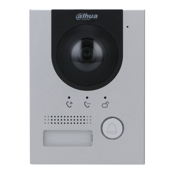
Overview The DHI-KTP01(S) IP Video Intercom kit is a complete solution that includes an outdoor station with wide-angle camera, a color indoor monitor, and accessories to mount and power the components. The kit allows a tenant to view and talk with visitors and remotely unlock doors all from the indoor monitor. -
Page 13: Rear Panel
1.1.2 Rear Panel Ref. Description Tamper Switch RS485_B: RS-485 communication RS485_A: RS-485 communication ALARM_NO: Switch quantity output ALARM_COM: Switch quantity output DOOR_BUTTON: Unlock button DOOR_FEEDBACK: Door contact feedback GND: GROUND DOOR_NC: Connected to access controller to control door locks DOOR_COM: Connected to access controller to control door locks DOOR_NO: Connected to access controller to control door locks RJ-45 Ethernet Connector... -
Page 14: Dimensions
1.1.3 Dimensions... -
Page 15: Dhi-Vth2421Fw-P Indoor Monitor
DHI-VTH2421FW-P Indoor Monitor 1.2.1 Front Panel Icon Name Description Tap to alert the call center in case of an emergency. Menu Tap to return to the main menu. Tap to answer the call. Call During communication, tap to hang up. During monitoring, tap to speak to VTO outdoor station. -
Page 16: Dimensions
1.2.3 Dimensions... -
Page 17: Installation And Configuration
Installation and Configuration The Video Intercom kit ships with all the components to mount the VTO Outdoor Station to surface of a wall. To flush-mount the VTO, order the VTM114 Flush-mount box. Before installing the camera consider the following: Review the “Installation Tips” section to help you choose an ideal mounting location. ... -
Page 18: Surface-Mount
Surface-mount Ref. Name Ref. Name VTO Outdoor Station M3×8 Screws Waterproof O-ring Waterproof Pad ST4×25 Self-tapping Screw Expansion Screw Surface-mount Box Wall Use the Surface-mount box as a guide and drill four holes into the installation medium. Place the four expansion screws into the pre-drilled holes. Install the waterproof pad to the rear of the surface mount box. -
Page 19: Flush-Mount
Flush-mount You must purchase the VTM114 Flush-mount box separately. Prior to installation, ensure that you can cut a space from the installation medium to accommodate the flush-mount rear panel. The dimensions of the space must greater than: 113.0 mm x 149.0 mm x 35.0 mm (4.45 in. x 5.87 in. x 1.38 in.) But less than: ... -
Page 20: Configuring Door Locks
Configuring Door Locks The VTO outdoor station supports connection to an electric or to a magnetic door lock mechanism. The VTO then can unlock the door when a tenant issues the door unlock command from the VTH indoor monitor. 2.5.1 Electric Door Lock Connect the positive end of the electric door lock to the NO port on the rear panel of the VTO outdoor station. -
Page 21: Configuration
Configuration Before configuration, install and power up all components. IP addresses and No. of every door station (VTO) and indoor monitor (VTH) have been planned. Scan QR code on the cover for details. 2.6.1 Initialize the VTH You must supply the following information before configuring the VTH: Password Email address (used to retrieve password)f... - Page 22 Tap OK. The system displays all intercoms devices on the same network. Select an uninitialized device, in this case the VTO outdoor station that came with the kit. Type the Password, then confirm the password, and enter an email address for the device. Tap OK to accept the credentials and to return to the Device page.
-
Page 23: Configure The Vth
2.6.2 Configure the VTH Tap Edit to configure the VTH device. Tap the MAIN button to indicate the VTH is the main monitor. Supply the Local IP Address, Subnet Mask, and the Gateway. Tap OK to complete the VTH configuration. -
Page 24: Configure The Vto
2.6.3 Configure the VTO Select the VTO outdoor station from the device list. Tap the MAIN button to indicate the VTO is the primary outdoor station. Enter the Local IP Address, Subnet Mask, and the Gateway address for the VTO. Tap the NTSC video standard. -
Page 25: Monitoring A Vto Station
Monitoring a VTO Station Select Monitor > Door, and then select the VTO you wish to monitor. Press the Star icon to add this VTO to the Favorite List. - Page 26 Dahua Technology USA 23 Hubble Irvine, CA 92618 Tel: (949) 679-7777 Fax: (949) 679-5760 Support: 877-606-1590 Sales: sales.usa@dahuatech.com Support: support.usa@dahuatech.com © 2020 Dahua Technology USA. All rights reserved. Design and specifications are subject to change without notice.
Need help?
Do you have a question about the VDP Series and is the answer not in the manual?
Questions and answers