Table of Contents
Advertisement
Quick Links
Advertisement
Chapters
Table of Contents

Related Manuals for Beckhoff C6032


Summary of Contents for Beckhoff C6032
- Page 1 Manual | EN C6032 Industrial PC 2023-4-17 | Version: 4.2...
-
Page 3: Table Of Contents
Grounding of the Industrial PC.................. 33 4.3.2 Connecting cables and power supply ................ 34 Switching the industrial PC on and off .................... 35 5 Beckhoff Device Manager ........................ 36 6 Decommissioning ........................... 38 Disconnecting the power supply and cables ................... 38 Disassembly and disposal....................... 39 7 Maintenance ............................ 40... - Page 4 Replacing the battery ....................... 43 7.2.2 Replacing the storage media ................... 45 7.2.3 Replacing the fan ...................... 47 8 Troubleshooting ............................ 48 9 Technical data ............................ 49 10 Appendix .............................. 50 10.1 Service and support ........................ 50 10.2 Approvals ............................ 50 Version: 4.2 C6032...
-
Page 5: Notes On The Documentation
Copyright © Beckhoff Automation GmbH & Co. KG. Publication of this document on websites other than ours is prohibited. Offenders will be held liable for the payment of damages. All rights reserved in the event of the grant of a patent, utility model or design. -
Page 6: For Your Safety
Exclusion of liability Beckhoff shall not be liable in the event of non-compliance with this documentation and thus the use of the devices outside the documented operating conditions. Signal words The signal words used in the documentation are classified below. -
Page 7: Fundamental Safety Instructions
• the operating instructions are in good condition and complete, and always available for reference at the location where the products are used. C6032 Version: 4.2... -
Page 8: Notes On Information Security
For your safety Notes on information security The products of Beckhoff Automation GmbH & Co. KG (Beckhoff), insofar as they can be accessed online, are equipped with security functions that support the secure operation of plants, systems, machines and networks. Despite the security functions, the creation, implementation and constant updating of a holistic security concept for the operation are necessary to protect the respective plant, system, machine and networks against cyber threats. -
Page 9: Product Overview
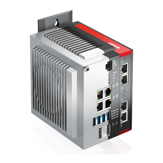
Product overview Product overview The C6032 Industrial PC is part of the series of ultra-compact industrial PCs for space-saving control cabinet installation. It is a high-performance device with a modular design. The second board level for modular interface and function extensions enables adaptation to specific applications and requirements. Various compact PCIe modules are available as ordering options for this. -
Page 10: Structure
Product overview Structure Fig. 1: C6032_structure - basic configuration Table 1: Legend - C6032 structure Component Description Protective conductor connection PE Low-resistance protective earthing and functional earthing of the industrial PC Power supply (X101) Connection of the power supply and external wiring of the industrial PC... -
Page 11: Interface Description
Product overview Interface description In the basic configuration, the C6032 includes the following interfaces: • Power supply (X101) • Ethernet RJ45 (X102-X105) • USB (X106-X109) • DisplayPorts (X110, X111) 3.2.1 Power supply The industrial PC is supplied with a nominal voltage of 24 V. The 2x2-pin voltage socket (X101) is used for connection to the power supply and the external wiring of the industrial PC. -
Page 12: Ethernet Rj45
Product overview 3.2.2 Ethernet RJ45 The C6032 has four Gigabit LAN ports (X102-X104). The 100Base-T and 1000Base-T Ethernet standards enable the connection of corresponding network components and data rates of 100/1000 Mbit/s. The required speed is selected automatically. The RJ45 connection technology with twisted-pair cables is used. The maximum length of the cable connection is 100 m. -
Page 13: Usb
C & D are feature common overcurrent protection (overcurrent detection). If an overcurrent occurs at one of the ports, the two jointly protected USB ports are switched off. For the device generation C6032-0070, USB port X108 is only compatible with USB 3.0. X106... -
Page 14: Displayport
The industrial PC has two DisplayPorts (X110, X111) that enable connection of devices with DisplayPort. It facilitates transfer of image signals. In addition, DVI signals can be transferred via an adapter. Please order it from your Beckhoff sales team, quoting order identifier C9900-Z468 adapter cable DisplayPort to DVI, 40 cm. -
Page 15: Optional Interfaces
PCIe module slot 1 Further modules are available on request. Any modules that are ordered are installed ex factory. Only Beckhoff PCIe compact modules are compatible with the device. The use of other Beckhoff modules or modules from other suppliers is prohibited. -
Page 16: Ethernet Rj45 Pcie Compact Module
The LED on the right indicates the speed of the data transfer. If the speed is 10 Mbit/s, the LED is not lit. At 100 Mbit/s the LED lights up orange, at 1000 Mbit/s it lights up green. Version: 4.2 C6032... -
Page 17: Rs232 Pcie Compact Module
6 7 8 9 Fig. 8: C6032_RS232 pin numbering Table 9: RS232 pin assignment Signal Type Description Signal in Receive Data Signal out Transmit Data Ground Ground Signal out Request to Send Signal in Clear to Send Signal in Ring Indicator C6032 Version: 4.2... -
Page 18: Rs422 Pcie Compact Module
Data-In - Receive 422 On delivery the interface is configured as a full duplex endpoint as standard – see table below. Table 11: RS422 standard configuration Function Status Echo Auto send Always send Auto receive Always receive Termination Version: 4.2 C6032... -
Page 19: Rs485 Pcie Compact Module
Pins 2 and 3 (data +) and pins 7 and 8 (data -) must be connected. On delivery the interface is configured as a half-duplex endpoint without echo as standard – see table below. Table 13: RS485 standard configuration Function Status Echo Auto send Always send Auto receive Always receive Termination C6032 Version: 4.2... -
Page 20: Cp-Link 4 Pcie Compact Module
Please observe that the CP-Link 4-PCIe compact module can only be operated in the PCIe module slot 1 (see chapter 3.1 Structure [} 10]). The CP-Link 4 technology is supported by the Beckhoff multi-touch Panel series CP29xx-0010 (built-in devices) and CP39xx-0010 (mounting arm devices). -
Page 21: Fig. 13 C6032_Cp-Link 4, Cu8802
CP-Link 4 cable. With this box, USB, DP/DVI and power supply can be transmitted together via the cable (One Cable Display Link). Do not connect an additional power supply to the control panel to avoid damage. Fig. 14 shows the wiring with the CU8803-0000. C6032 Version: 4.2... -
Page 22: Status Leds
One-cable technology (OCT) enables the communication between PC and UPS to be transmitted together with the power supply, so that only one cable is required. The colors and flashing intervals have the following meanings: Version: 4.2 C6032... -
Page 23: Pwr Led
Flashing Checksum error during the I2C transmission in the bootloader Cyan Flashing (2 s) contact Beckhoff Service 3.4.3 HDD LED The HDD LED indicates the activity of the storage medium. The colors and flashing intervals have the following meanings: Table 17: Meaning of the HDD LED... -
Page 24: Table 18 Meaning Of The Tc Led
Product overview Table 18: Meaning of the TC LED Color Flashing interval Meaning Green Steadily lit TwinCAT Run Mode Blue Steadily lit TwinCAT Config Mode Steadily lit TwinCAT Stop TwinCAT not started Version: 4.2 C6032... -
Page 25: Name Plate
Fig. 16: C6032_name plate Table 19: Legend C6032 name plate Description Manufacturer, including address Model: The last four digits indicate the device generation. Serial number (BTN) Date of manufacture Mainboard Main memory Storage media Power supply: 24 V... -
Page 26: Commissioning
4. Check your delivery for completeness by comparing it with your order. 5. Check the contents for visible shipping damage. 6. In case of discrepancies between the package contents and the order, or in case of transport damage, please inform Beckhoff Service (see Chapter 10.1 Service and support). Version: 4.2 C6032... -
Page 27: Control Cabinet Installation
Commissioning Control cabinet installation The C6032 Industrial PC is designed for mounting in control cabinets in machine and plant engineering applications. The environmental conditions specified for operation must be observed (see chapter 9 Technical data [} 49]). Using different mounting plates, you can align the cable entry based on the application requirements. -
Page 28: Mounting Options
PC as required to align the connections in the control cabinet. You have the following mounting options, which are shown in Fig. 19: • Connections point upwards (A) • Connections point downwards (B) • Connections point to the right (C) • Connections point to the left (D) Version: 4.2 C6032... -
Page 29: Fig. 19: C6032_Mounting Options Mounting Plate 2
Commissioning Fig. 19: C6032_mounting options mounting plate 2 C6032 Version: 4.2... -
Page 30: Dimensions
NOTE Extreme environmental conditions Extreme environmental conditions can cause damage to the device. • Avoid extreme environmental conditions. • Protect the device against dust, moisture and heat. • Do not block the ventilation slots of the device. Version: 4.2 C6032... -
Page 31: Fig. 22 C6032_Control Cabinet Installation Mounting Plates
1. Place the fastening screws in the drill holes in the rear panel of the control cabinet. 2. Hang the PC on the screws at the marked points of the mounting plate (see Fig. 22). 3. Tighten the fastening screws. ð You have successfully installed the industrial PC in the control cabinet. C6032 Version: 4.2... -
Page 32: Connecting The Industrial Pc
Devices connected to the industrial PC with their own power supply must have the same potential for the PE and "0 V" conductors as the industrial PC (no potential difference). 230 V 24 V Grounding busbar Fig. 23: C6032_wiring example Version: 4.2 C6032... -
Page 33: Grounding Of The Industrial Pc
The functional earth is necessary for the EMC of the device. The functional earthing is also established via the earthing connection between the protective conductor connection on the device and the central grounding point of the control cabinet in which the PC is installed. C6032 Version: 4.2... -
Page 34: Connecting Cables And Power Supply
4. Fasten the power cable to the voltage connector of the industrial PC. 5. Connect the PC to your external 24 V power supply. 6. Switch on the 24 V power supply. 7. Measure the voltage on the power supply plug of the PC. Version: 4.2 C6032... -
Page 35: Switching The Industrial Pc On And Off
When you switch on the industrial PC for the first time, the pre-installed operating system (optional) will be started. For any additional hardware you have connected, you have to install the drivers yourself afterwards. In addition, the Beckhoff Device Manager starts automatically. The Device Manager is a software from Beckhoff that supports you in configuring the PC. -
Page 36: Beckhoff Device Manager
• User name: Administrator • Password: 1 You also have the option of using the Beckhoff Device Manager to remotely configure the industrial PC via a web browser. More detailed information is available in the Beckhoff Device Manager manual. First start Beckhoff Device Manager When your industrial PC is booted for the first time, the Beckhoff Device Manager also starts automatically for the first time. -
Page 37: Fig. 25 Beckhoff Device Manager - Start Page
Secure passwords Strong passwords are an important prerequisite for a secure system. Beckhoff supplies the device images with standard user names and standard passwords for the operating system. It is imperative that you change these. Controllers are shipped without a password in the UEFI/BIOS setup. Beckhoff recommends assigning a password here as well. -
Page 38: Decommissioning
5. Make a note of the wiring of all data transmission cables if you want to restore the cabling with another device. 6. Disconnect all data transfer cables from the industrial PC. 7. Finally, disconnect the ground connection. Version: 4.2 C6032... -
Page 39: Disassembly And Disposal
• Electronic parts such as fans and circuit boards must be disposed of in accordance with national electronic scrap regulations. • Stick insulating tape over the poles of the CR2032 battery on the motherboard and dispose of the battery via the local battery recycling. C6032 Version: 4.2... -
Page 40: Maintenance
Repair Only the vendor may repair the device. If a repair should be necessary, contact Beckhoff Service (see Chapter 10.1 Service and support [} 50]). Cleaning... -
Page 41: Table 21 Replacement Recommendations For Pc Components
NOTE Use of incorrect spare parts The use of spare parts not ordered from Beckhoff Service can lead to unsafe and faulty operation. • Only use spare parts that you have ordered from Beckhoff Service. Beckhoff industrial PCs are manufactured from components of the highest quality and robustness. They are selected and tested for best interoperability, long-term availability and reliable function under the specified environmental conditions. -
Page 42: Fig. 27 C6032_Access To Battery And Storage Medium
To do this, remove the four Torx TX10 screws and remove the cover (see fig. 27). Fig. 27: C6032_access to battery and storage medium You now have access to the battery (1) and storage medium (2) (see fig. 28). Fig. 28: C6032_battery and storage medium Version: 4.2 C6032... -
Page 43: Replacing The Battery
It is used to supply power to the clock integrated on the motherboard. If the battery is depleted or missing, the date and time are displayed incorrectly. Replacement batteries should only be obtained from Beckhoff Service (see Chapter 10.1 Service and support). - Page 44 Maintenance To dispose of the battery, remove it, tape off the poles and put it in the battery disposal. Version: 4.2 C6032...
-
Page 45: Replacing The Storage Media
If you want to exchange a storage medium according to Beckhoff's recommendation, you must copy the data from the old to the new storage medium. You can use the Beckhoff Service Tool (BST) for this purpose. The BST is a graphical backup and restore program for industrial PCs with a Windows operating system. You can create an image of your operating system and use it to back up the operating system. -
Page 46: Fig. 31 C6032_Replacing The Storage Medium
5. Replace the fastening screw and tighten it with a tightening torque of approx. 0.3 Nm. ð You have replaced the SSD. The old SSD must be disposed of in accordance with the national electronic scrap regulations. Version: 4.2 C6032... -
Page 47: Replacing The Fan
• Only replace the fan with a replacement fan from Beckhoff Service. The fan ensures optimum cooling of the industrial PC. Order a replacement fan only from Beckhoff. To do this, contact Beckhoff Service (see Chapter 10.1 Service and Support). -
Page 48: Troubleshooting
Nothing happens after the Missing power supply of the Check the power supply cable Industrial PC has been switched on Industrial PC Call Beckhoff Service Other cause The Industrial PC does not boot Setup settings are incorrect Check the setup settings... -
Page 49: Technical Data
Technical data Technical data Table 24: Technical data Product designation C6032 Dimensions (W x H x D) 132 x 133 x 102 mm, without mounting plate Weight approx. 2100 g without mounting plate approx. 2350 g with mounting plate Supply voltage 20.4-30 V (24 V... -
Page 50: Appendix
Hülshorstweg 20 33415 Verl Germany Phone: + 49 5246/963-0 email: info@beckhoff.de The addresses of the worldwide Beckhoff branches and agencies can be found on our website at http:// www.beckhoff.com/. You will also find further documentation for Beckhoff components there. 10.2 Approvals The following table shows the approvals of the Industrial PC based on the device generation: Table 25: C6032 approvals... - Page 51 FCC approvals for Canada FCC: Canadian Notice This device does not exceed the class A limits for radiation, as specified by the Radio Interference Regulations of the Canadian Department of Communications. C6032 Version: 4.2...
- Page 52 C6032_mounting plate side panel....................Fig. 22 C6032_control cabinet installation mounting plates..............Fig. 23 C6032_wiring example......................... Fig. 24 Beckhoff Device Manager - Change passwords ................Fig. 25 Beckhoff Device Manager – Start page ..................Fig. 26 C6032_positions fastening screws....................Fig. 27 C6032_access to battery and storage medium................
- Page 53 List of tables List of tables Table 1 Legend - C6032 structure ......................Table 2 Voltage socket pin assignment ....................Table 3 Controller classification based on device generation ..............Table 4 Ethernet interface pin assignment....................Table 5 USB interface pin assignment......................
- Page 55 More Information: www.beckhoff.com/C6032 Beckhoff Automation GmbH & Co. KG Hülshorstweg 20 33415 Verl Germany Phone: +49 5246 9630 info@beckhoff.com www.beckhoff.com...
Need help?
Do you have a question about the C6032 and is the answer not in the manual?
Questions and answers