
Related Manuals for Beckhoff C6017-0010


Summary of Contents for Beckhoff C6017-0010
- Page 1 Installation and Operating instructions for C6017-0010 Ultra compact Industrial PC Version: 1.0 Datum: 04.10.2019...
-
Page 3: Table Of Contents
Network connection LAN1, LAN2 (X102, X103) 2.5.3 DisplayPort (X104) 2.5.4 USB2.0 output (X105) 2.5.5 USB3.0 output (X106) 2.5.6 Network connection LAN3, LAN4 (X201, X202) 2.5.7 USB2.0 output (X203, X204) Protective Earthing (PE) Status LEDs Access to the battery and the memory devices 3 Installation C6017-0010... - Page 4 5 Troubleshooting 6 Assembly dimensions 7 Technical Data 8 Appendix Beckhoff Support and Service 8.1.1 Beckhoff branches and partner companies 8.1.2 Beckhoff company headquarters Approvals for USA and Canada FCC Approvals for the United States of America FCC Approval for Canada...
-
Page 5: Foreword
Modifications to hardware or software configurations other than those described in the documentation are not permitted, and nullify the liability of Beckhoff Automation GmbH & Co. KG. 1.1.6 Delivery conditions In addition, the general delivery conditions of the company Beckhoff Automation GmbH & Co. KG apply. C6017-0010... -
Page 6: Description Of Safety Symbols
CAUTION Hazard to devices and environment If you do not adhere the notice adjoining this symbol, there is obvious hazard to materials and environment. Attention Note or pointer This symbol indicates information that contributes to better understanding. Note C6017-0010... -
Page 7: Basic Safety Measures
• if connecting cables internal to the PC are removed or inserted during operation. • if plug-in cards are removed or inserted when the PC is switched on. C6017-0010... -
Page 8: Operator's Obligation To Exercise Diligence
1.4.3 Operator requirements Anyone who uses the Industrial PC must have read these operating instructions and must be familiar with all the functions of the software installed on the Industrial PC to which he has access. C6017-0010... -
Page 9: Product Description
Despite passive cooling, the C6017 is suitable for a temperature range of up to 55 °C (C6017-0010) or 50 °C (C6017-0020). With a 30 GB 3D MLC M.2 SSD and a Windows Embedded Compact 7 operating system, it is fully operational in the basic configuration. Windows 7 or Windows 10 operating systems are optionally available. - Page 10 • passive, fanless cooling with one-sided cool plate • protection class IP20 • operating temperature 0...55 °C • compact dimensions (W x H x D) 82 x 82 x 66 mm (3.2" x 3.2" x 2.6") without mounting plate C6017-0010...
-
Page 11: Appropriate Use
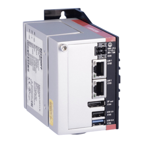
Product Description 2.2 Appropriate Use The C6017-0010 is an Industrial PC for space-saving control cabinet installation. Risk of explosion! The Industrial PC must not be used where there is a risk of explosion. Danger 2.3 Access to the connectors The connectors of the Industrial PC are located at the front side of the housing. -
Page 12: Interfaces In Basic Configuration
2.4.4 USB2.0 output (X105) The USB interface (X105) is used for connecting peripheral devices with USB connection. USB2.0 standard is supported. 2.4.5 USB3.0 output (X106) The USB interface (X106) is used for connecting peripheral devices with USB connection. USB3.0 standard is supported. C6017-0010... -
Page 13: Interfaces With Order Option C9900-E302
The RJ-45 connectors (X201, X202) allow the PC to be connected to a 100/1000 BASE-T Local Area Network (LAN). 2.5.7 USB2.0 output (X203, X204) The USB interfacees (X203, X204) are used for connecting peripheral devices with USB connection. USB2.0 standard is supported. C6017-0010... -
Page 14: Protective Earthing (Pe)
24V cable, otherwise electricity can still flow due to the screen in dependence of the device. Any connected devices with its own power supply must have the same potential for “PE” and “GND” like the Panel PC system (no potential difference). C6017-0010... -
Page 15: Status Leds
Product Description 2.7 Status LEDs The Status LEDs are located at the side of the C6017-0010: Status LEDs Description of the Status LEDs: HDD (Hard disk): Access to the memory device TC (TwinCAT): TwinCAT Stop blue TwinCAT Config blue/ red blinking... -
Page 16: Access To The Battery And The Memory Devices
Replace battery only with the identical type or an alternative type recommended by the manufacturer. Notice correct polarity! WARNING Handling of Batteries Batteries should not be recharged, exposed to fire, opened, short-circuited and they WARNING should be protected against sunlight and moisture. C6017-0010... -
Page 17: Installation
4. Please keep the associated paperwork. It contains important information for handling the unit. 5. Check the contents for visible shipping damage. 6. If you notice any shipping damage or inconsistencies between the contents and your order, you should notify Beckhoff Service. C6017-0010... -
Page 18: Installation Of The Pc In The Control Cabinet
Installation 3.2 Installation of the PC in the control cabinet The C6017-0010 Industrial PC is designed for mounting in control cabinets for machine and plant engineering applications. The ambient conditions specified for operation must be observed (see chapter Technical Data). -
Page 19: Power Supply Of The Industrial Pc
1. Check that the external power supply is providing the correct voltage. 2. Insert the power supply cable that you have assembled into the Industrial PC's power supply socket. Then connect it to your external 24 V power supply. C6017-0010... -
Page 20: Configuration For Shutting Down The Pc
Once the PC has shut down, the Power Status output is switched from 24 V to 0 V. Via this output a signal lamp can be connected or a contactor for de-energizing the whole system. The maximum load for the Power Status output is 0.5 A and a suitable fuse should be provided. C6017-0010... -
Page 21: Connecting The Industrial Pc
The low-resistance protective earthing of the Industrial PC is established via the screw connection (PE). Establish a low-impedance connection from the earthing point on the Industrial PC housing (see chapter Protective Earthing (PE)) to the central earthing point on the control cabinet wall, in which the computer is being installed. C6017-0010... -
Page 22: Operating Instructions
If the PC was ordered without operating system, you have to install the operating system and the driver software for any auxiliary hardware yourself. Please follow the instructions in the documentation for the operating system and the additional devices. C6017-0010... -
Page 23: Servicing And Maintenance
Housing components (polycarbonate, polyamide (PA6.6)) are suitable for plastic recycling • Metal parts can be sent for metal recycling • Electronic parts such as disk drives and circuit boards must be disposed of in accordance with national electronics scrap regulations. C6017-0010... -
Page 24: Troubleshooting
Procedure Nothing happens after the Industrial No power supply to the Industrial Check power supply cable PC has been switched on Call Beckhoff Service Other cause The Industrial PC does not boot Setup settings are incorrect Check the setup settings... -
Page 25: Assembly Dimensions
Assembly dimensions 6 Assembly dimensions Industrial PC C6017-0010, with mounting sheet for rear wall installation Notice mounting orientation The assembly of the unit must take place with the orientation diagrammed here. Attention All dimensions in mm. Front view Side view... - Page 26 Assembly dimensions Industrial PC C6017-0010 with option C9900-E302, with mounting sheet C9900-M664/ -M665 for side wall installation Notice mounting orientation The assembly of the unit must take place with the orientation diagrammed here. Attention All dimensions in mm. Side view...
- Page 27 Assembly dimensions Industrial PC C6017-0010 with option C9900-E302, with mounting sheet C9900-M666/ -M667 for DIN rail installation Notice mounting orientation The assembly of the unit must take place with the orientation diagrammed here. Attention All dimensions in mm. Front view...
-
Page 28: Technical Data
Technical Data 7 Technical Data Risk of explosion! Do not use the Industrial PC in areas of explosive hazard! Danger Product name C6017-0010 Dimensions (B x H x T) see chapter Assembly dimensions Weight approx. 550 g without mounting sheet approx. -
Page 29: Appendix
Please contact your Beckhoff branch office or partner company for local support and service on Beckhoff products! The contact addresses for your country can be found in the list of Beckhoff branches and partner companies: www.beckhoff.com. You will also find further documentation for Beckhoff components there. -
Page 30: Approvals For Usa And Canada
Technological changes to the device may cause the loss of the FCC approval. Note 8.4 FCC Approval for Canada FCC: Canadian Notice This equipment does not exceed the Class A limits for radiated emissions as described in the Radio Interference Regulations of the Canadian Department of Communications. C6017-0010...
Need help?
Do you have a question about the C6017-0010 and is the answer not in the manual?
Questions and answers