Sign In
Upload
Manuals
Brands
Beckhoff Manuals
Industrial PC
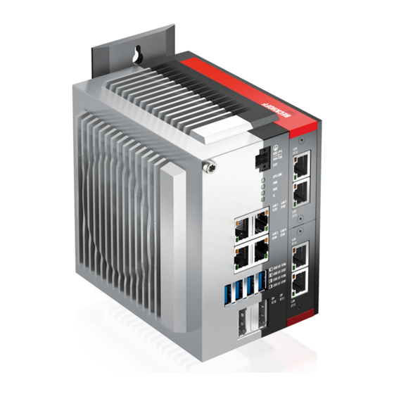
C6032
Beckhoff C6032 Manuals
Manuals and User Guides for Beckhoff C6032. We have
3
Beckhoff C6032 manuals available for free PDF download: Manual
Beckhoff C6032 Manual (55 pages)
Brand:
Beckhoff
| Category:
Industrial PC
| Size: 11 MB
Table of Contents
Table of Contents
3
Notes on the Documentation
5
For Your Safety
6
Signal Words
6
Intended Use
6
Fundamental Safety Instructions
7
Operator's Obligation to Exercise Diligence
7
Notes on Information Security
8
Product Overview
9
Structure
10
Fig. 1 C6032_Structure - Basic Configuration
10
Table 1 Legend - C6032 Structure
10
Table 2 Voltage Socket Pin Assignment
11
Fig. 2 C6032_Voltage Socket Pin Numbering
11
Power Supply
11
Interface Description
11
Ethernet RJ45
12
Fig. 3 C6032_Ethernet Interface Pin Numbering
12
Table 3 Controller Classification Based on Device Generation
12
Table 4 Ethernet Interface Pin Assignment
12
Usb
13
Fig. 4 C6032_USB Interface Pin Numbering
13
Table 5 USB Interface Pin Assignment
13
Displayport
14
Fig. 5 C6032_Displayport Pin Numbering
14
Table 6 Pin Assignment of Displayport
14
Table 7 USB Interface Pin Assignment
15
Fig. 6 C6032_USB Interface Pin Numbering
15
USB 3.0 Pcie Compact Module
15
Optional Interfaces
15
Ethernet RJ45 Pcie Compact Module
16
Fig. 7 C6032_Ethernet Interface Pin Numbering
16
Table 8 Ethernet Interface Pin Assignment
16
RS232 Pcie Compact Module
17
Fig. 8 C6032_RS232 Pin Numbering
17
Table 9 RS232 Pin Assignment
17
RS422 Pcie Compact Module
18
Fig. 9 C6032_RS422 Pin Numbering
18
Table 10 RS422 Pin Assignment
18
Table 11 RS422 Standard Configuration
18
Table 13 RS485 Standard Configuration
19
Fig. 10 C6032_RS485 Pin Numbering
19
Table 12 RS485 Pin Assignment
19
RS485 Pcie Compact Module
19
CP-Link 4 Pcie Compact Module
20
Fig. 11: C6032_CP-Link 4
20
Fig. 12 C6032_CP-Link 4 Pin Numbering
20
Table 14 CP-Link 4 Pin Assignment
20
Fig. 13 C6032_CP-Link 4, CU8802
21
Status Leds
22
Ups-Oct Led
22
Fig. 14 C6032_CP-Link 4, CU8803
22
Fig. 15 C6032_Status Leds
22
Table 17 Meaning of the HDD LED
23
Table 16 Meaning of the PWR LED
23
Hdd Led
23
Table 15 Meaning of the UPS-OCT LED
23
Tc Led
23
Pwr Led
23
Table 18 Meaning of the TC LED
24
Name Plate
25
Fig. 16 C6032_Name Plate
25
Table 19 Legend C6032 Name Plate
25
Commissioning
26
Transport and Unpacking
26
Control Cabinet Installation
27
Fig. 17 C6032_Mounting Plates
27
Table 20 Mounting Plate Ordering Options
27
Mounting Options
28
Fig. 18: C6032_Mounting Options Mounting Plate 1
28
Fig. 19: C6032_Mounting Options Mounting Plate 2
29
Dimensions
30
Installation in the Control Cabinet
30
Fig. 20 C6032_Mounting Plate Rear Panel
30
Fig. 21 C6032_Mounting Plate Side Panel
30
Fig. 22 C6032_Control Cabinet Installation Mounting Plates
31
Connecting the Industrial PC
32
Fig. 23 C6032_Wiring Example
32
Grounding of the Industrial PC
33
Connecting Cables and Power Supply
34
Switching the Industrial PC on and off
35
Fig. 24 Beckhoff Device Manager - Change Passwords
36
Beckhoff Device Manager
36
Fig. 25 Beckhoff Device Manager - Start Page
37
Decommissioning
38
Disconnecting the Power Supply and Cables
38
Disassembly and Disposal
39
Fig. 26 C6032_Positions Fastening Screws
39
Maintenance
40
Cleaning
40
Table 21 Replacement Recommendations for PC Components
41
Fig. 27 C6032_Access to Battery and Storage Medium
42
Fig. 28 C6032_Battery and Storage Medium
42
Table 22 Technical Data of the Battery
43
Fig. 29 C6032_Battery Change
43
Replacing the Battery
43
Replacing the Storage Media
45
Fig. 30 C6032_SATA Assignment
45
Fig. 31 C6032_Replacing the Storage Medium
46
Replacing the Fan
47
Fig. 32 C6032_Access Fan
47
Troubleshooting
48
Table 23 Troubleshooting
48
Technical Data
49
Table 24 Technical Data
49
Appendix
50
Service and Support
50
Approvals
50
Table 25 C6032 Approvals
50
List of Figures
52
Advertisement
Beckhoff C6032 Manual (53 pages)
Brand:
Beckhoff
| Category:
Industrial PC
| Size: 11 MB
Table of Contents
Table of Contents
3
1 Notes on the Documentation
5
2 For Your Safety
6
Description of Safety Symbols
6
Intended Use
6
Fundamental Safety Instructions
7
Operator's Obligation to Exercise Diligence
7
3 Product Overview
8
Structure
9
Fig. 1 C6032_Structure - Basic Configuration
9
Table 1 Key - C6032 Structure
9
Interface Description
10
Power Supply
10
Fig. 2 C6032_Power Socket Pin Numbering
10
Table 2 Power Socket Pin Assignment
10
Ethernet RJ45
11
Fig. 3 C6032_Ethernet Interface Pin Numbering
11
Table 3 Controller Classification Based on Device Generations
11
Table 4 Ethernet Interface Pin Assignment
11
Usb
12
Fig. 4 C6032_USB Interface Pin Numbering
12
Table 5 USB Interface Pin Assignment
12
Displayport
13
Fig. 5 C6032_Displayport Pin Numbering
13
Table 6 Pin Assignment of Displayport
13
Optional Interfaces
14
USB 3.0 Pcie Compact Module
14
Fig. 6 C6032_USB Interface Pin Numbering
14
Table 7 USB Interface Pin Assignment
14
Ethernet RJ45 Pcie Compact Module
15
Fig. 7 C6032_Ethernet Interface Pin Numbering
15
Table 8 Ethernet Interface Pin Assignment
15
RS232 Pcie Compact Module
16
Fig. 8 C6032_RS232 Pin Numbering
16
Table 9 RS232 Pin Assignment
16
RS422 Pcie Compact Module
17
Fig. 9 C6032_RS422 Pin Numbering
17
Table 10 RS422 Pin Assignment
17
Table 11 RS422 Standard Configuration
17
RS485 Pcie Compact Module
18
Fig. 10 C6032_RS485 Pin Numbering
18
Table 12 RS485 Pin Assignment
18
Table 13 RS485 Standard Configuration
18
CP-Link 4 Pcie Compact Module
19
Fig. 11: C6032_CP-Link 4
19
Fig. 12 C6032_CP-Link 4 Pin Numbering
19
Table 14 CP-Link 4 Pin Assignment
19
Status Leds
20
Fig. 13 C6032_CP-Link 4, CU8802
20
Fig. 14 C6032_CP-Link 4, CU8803
20
Ups-Oct Led
21
Pwr Led
21
Fig. 15 Status Leds
21
Table 15 Meaning of the UPS-OCT LED
21
Hdd Led
22
Tc Led
22
Table 16 Meaning of the PWR LED
22
Table 17 Meaning of the HDD LED
22
Table 18 Meaning of the TC LED
22
Name Plate
23
Fig. 16 C6032 _Name Plate Example
23
Table 19 Key - C6032 Name Plate
23
4 Commissioning
24
Transport and Unpacking
24
Installation in the Control Cabinet
25
Fig. 17 C6032 _Mounting Plates
25
Table 20 Mounting Plate Ordering Options
25
Mounting Options
26
Fig. 18: C6032_Mounting Options for Mounting Plate 1
26
Fig. 19: C6032 _Mounting Options for Mounting Plate 2
27
Dimensions
28
Fig. 20 C6032 _Mounting Plate Narrow Side
28
Fig. 21 C6032 _Mounting Plate Side Panel
28
Installation in the Control Cabinet
29
Fig. 22 C6032 _Mounting Plates for Control Cabinet Installation
29
Connecting the Industrial PC
30
Fig. 23 C6032 _Wiring Example
30
Grounding of the Industrial PC
31
Connecting Cables and Power Supply
32
Switching the Industrial PC on and off
33
5 Beckhoff Device Manager
34
Fig. 24 Beckhoff Device Manager - Change Passwords
34
Fig. 25 Beckhoff Device Manager Home Page
35
Table 21 Password Generation
36
6 Decommissioning
37
Disconnecting the Power Supply and Cables
37
Disassembly and Disposal
38
Fig. 26 C6032 _Position of the Fastening Screws
38
7 Maintenance
39
Cleaning
39
Table 22 Replacement Recommendations for PC Components
40
Fig. 27 C6032 _Access to Battery and Storage Media
41
Fig. 28 C6032 _Battery and Storage Media
41
Replacing the Battery
42
Fig. 29 C6032 _Battery Change
42
Table 23 Technical Data of the Battery
42
Replacing the Storage Media
43
Fig. 30 C6032_SATA Assignment
43
Replacing the Fan
44
Fig. 31 C6032 _Replace Storage Media
44
Fig. 32 C6032_Fan Access
45
8 Troubleshooting
46
Table 24 Troubleshooting
46
9 Technical Data
47
Table 25 Technical Data
47
10 Appendix
48
Service and Support
48
Approvals
49
Table 26 Certifications C6032
49
List of Figures
50
Beckhoff C6032 Manual (30 pages)
Brand:
Beckhoff
| Category:
Industrial PC
| Size: 6 MB
Table of Contents
Table of Contents
3
1 Notes on the Documentation
5
2 For Your Safety
6
Description of Safety Symbols
6
Intended Use
6
Fundamental Safety Instructions
7
Operator's Obligation to Exercise Diligence
7
3 Product Overview
8
Fig. 1 C6032
8
Structure
9
Fig. 2 C6032 Structure - Basic Configuration
9
Table 1 Key - C6032 Structure
9
Fig. 3 C6032_Standard Connections
10
Fig. 4 C6032_Voltage Connector
10
Table 2 Pin Assignment Voltage Connector
10
Fig. 5 C6032_Status Leds
11
Table 3 Meaning of the Status Leds
11
Fig. 6 C6032_Modules
12
Name Plate
13
Fig. 7 C6032_Name Plate
13
Table 4 Key to Name Plate
13
4 Commissioning
14
Transport and Unpacking
14
Installation in the Control Cabinet
14
Table 5 Mounting Plate Ordering Options
14
Fig. 8 C6032_Mounting Plates
15
Dimensions
16
Fig. 9 C6032_Mounting Plate on the Rear Panel
16
Fig. 10 C6032_Mounting Plate on the Side Panel
17
Preparation of the Control Cabinet
17
Connecting the Industrial PC
18
5 Operation
19
Switching the Industrial PC on and off
19
Decommissioning
20
6 Maintenance
21
Cleaning
21
Replacement of Device Components
21
Fig. 11 C6032_Access to Battery and Storage Media
21
Replacing the Battery
22
Replacing the Storage Media
22
Fig. 12 C6032_Access to the Fan
23
Replacing the Fan
23
7 Troubleshooting
24
Table 6 Troubleshooting
24
8 Technical Data
25
Table 7 Technical Data
25
9 Appendix
26
Service and Support
26
Approvals
27
Advertisement
Advertisement
Related Products
Beckhoff C6030-0060
Beckhoff C6030
Beckhoff C6030-0070
Beckhoff C6032-0060
Beckhoff C6032-0070
Beckhoff C6030-0080
Beckhoff C6015-0010
Beckhoff C6015-0020
Beckhoff C6025
Beckhoff C6027
Beckhoff Categories
Touch terminals
Industrial PC
Control Unit
Industrial Equipment
Control Panel
More Beckhoff Manuals
Login
Sign In
OR
Sign in with Facebook
Sign in with Google
Upload manual
Upload from disk
Upload from URL