Table of Contents
Advertisement
Quick Links
Advertisement
Chapters
Table of Contents

Related Manuals for Beckhoff C6040


Summary of Contents for Beckhoff C6040
- Page 1 Manual | EN C6040 Industrial PC 2024-06-04 | Version: 1.0...
-
Page 3: Table Of Contents
Grounding of the Industrial PC.................. 25 4.3.2 Connecting cables and power supply ................ 26 Switching the industrial PC on and off .................... 27 5 Beckhoff Device Manager ........................ 28 6 Decommissioning ........................... 30 Disconnecting the power supply and cables ................... 30 Disassembly and disposal....................... 31 7 Maintenance ............................ 32... - Page 4 Table of contents 10.1 Service and support ........................ 41 10.2 Approvals ............................ 42 Version: 1.0 C6040...
-
Page 5: Notes On The Documentation
EP1590927, EP1789857, EP1456722, EP2137893, DE102015105702 and similar applications and registrations in several other countries. ® EtherCAT is registered trademark and patented technology, licensed by Beckhoff Automation GmbH, Germany Copyright © Beckhoff Automation GmbH & Co. KG, Germany. The distribution and reproduction of this document as well as the use and communication of its contents without express authorization are prohibited. -
Page 6: For Your Safety
Exclusion of liability Beckhoff shall not be liable in the event of non-compliance with this documentation and thus the use of the devices outside the documented operating conditions. -
Page 7: Fundamental Safety Instructions
• the operating instructions are in good condition and complete, and always available for reference at the location where the products are used. C6040 Version: 1.0... -
Page 8: Notes On Information Security
For your safety Notes on information security The products of Beckhoff Automation GmbH & Co. KG (Beckhoff), insofar as they can be accessed online, are equipped with security functions that support the secure operation of plants, systems, machines and networks. Despite the security functions, the creation, implementation and constant updating of a holistic security concept for the operation are necessary to protect the respective plant, system, machine and networks against cyber threats. -
Page 9: Product Overview
Product overview Product overview The C6040 Industrial PC is part of the series of ultra-compact industrial PCs for space-saving control cabinet installation. At the same time, it is even more powerful than previous devices from the C60xx series. Thanks to the available processors, the industrial PC can be used for the following applications, among others: •... -
Page 10: Structure
Product overview Structure Fig. 1: Structure – basic configuration Table 1: Legend – C6040 structure Component Description Mounting plate Plate for mounting the industrial PC via the rear panel in the control cabinet Protective conductor connection PE Low-resistance protective earthing and functional earthing of... -
Page 11: Interface Description
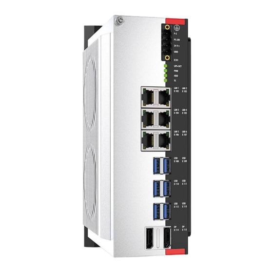
Product overview Interface description In the basic configuration, the C6040 includes the following interfaces: • Power supply (X101) • Ethernet RJ45 (X102-X107) • USB (X108-X113) • DisplayPort (X114, X115) 3.2.1 Power supply The industrial PC is supplied with a nominal voltage of 24 V. The 4-pin voltage socket (X101) is used for connection to the power supply and the external wiring of the industrial PC. -
Page 12: Ethernet Rj45
3.2.2 Ethernet RJ45 The C6040 has six Gigabit LAN ports (X102-X107). The Ethernet standards 100Base-T and 1000Base-T enable the connection of corresponding network components and data rates of 100/1000 MBit/s for X102 (LAN1). The Ethernet standards 100Base-T, 1000Base-T and 2500Base-T allow for X103-X107 (LAN2- LAN6) the connection of corresponding network components and data rates of 100/1000/2500 Mbit/s. -
Page 13: Table 4 Meaning Of Leds
Product overview Table 4: Meaning of LEDs Interface Mbit/s LAN1 Lights-up orange 1000 Lights up green LAN2-LAN6 Is not lit 1000 Lights-up orange 2500 Lights up green C6040 Version: 1.0... -
Page 14: Usb
USB B X108 X109 USB A USB B X110 X111 USB A USB B X112 X113 Fig. 4: USB interface pin numbering Table 5: USB interface pin assignment Connection Vbus StdA_SSRX - StdA_SSRX + GND_DRAIN StdA_SSTX - StdA_SSTX + Version: 1.0 C6040... -
Page 15: Displayport
The industrial PC has two DisplayPorts (X114, X115) that enable connection of devices with DisplayPort. It facilitates transfer of image signals. In addition, DVI signals can be transferred via an adapter. Please order it from your Beckhoff sales team, quoting order identifier C9900-Z468 adapter cable DisplayPort to DVI, 40 cm. -
Page 16: Status Leds
Table 7: Meaning of the UPS-OCT LED Color Flashing interval Meaning None Steadily lit No UPS-OCT connected Blue Flashing Bootloader active Yellow Steadily lit Moderate signal quality Green Steadily lit Good signal quality Steadily lit Poor signal quality Version: 1.0 C6040... -
Page 17: Pwr Led
Flashing Checksum error during the I2C transmission in the bootloader Cyan Flashing (2 s) contact Beckhoff Service 3.3.3 HDD LED The HDD LED indicates the activity of the storage medium. The colors and flashing intervals have the following meanings: Table 9: Meaning of the HDD LED... -
Page 18: Name Plate
The name plate provides information on the equipment fitted to the industrial PC. The name plate shown here serves only as an example. Fig. 7: Name plate Table 11: Legend C6040 name plate Description Manufacturer, including address Model: The last four digits indicate the device generation. -
Page 19: Commissioning
4. Check the contents for visible shipping damage. 5. In case of discrepancies between the package contents and the order, or in case of transport damage, please inform Beckhoff Service (see Chapter 10.1 Service and Support [} 41]). C6040 Version: 1.0... -
Page 20: Control Cabinet Installation
Commissioning Control cabinet installation The C6040 Industrial PC is designed for mounting in control cabinets in machine and plant engineering applications. The environmental conditions specified for operation must be observed (see chapter 9 Technical data [} 40]). Using different mounting plates, you can align the cable entry based on the application requirements. -
Page 21: Mounting Options
With the optional mounting plate 2, you can mount the industrial PC only via the right-hand side panel. Before screwing on the plate, you can align the PC as follows (see Fig. 10): • Connections point to the right (A) • Connections point to the left (B) Fig. 10: Mounting options for mounting plate 2 C6040 Version: 1.0... -
Page 22: Dimensions
• Protect the device against dust, moisture and heat. • Do not block the ventilation slots of the device. When installing in the control cabinet, note that there must be 5 cm of free space around the device for air circulation. Mounting via mounting plates Version: 1.0 C6040... -
Page 23: Fig. 13 Mounting Plates For Control Cabinet Installation
1. Place the fastening screws in the drill holes in the rear panel of the control cabinet. 2. Hang the PC on the screws at the marked points of the mounting plate (see Fig. 13). 3. Tighten the fastening screws. ð You have successfully installed the industrial PC in the control cabinet. C6040 Version: 1.0... -
Page 24: Connecting The Industrial Pc
Devices connected to the industrial PC with their own power supply must have the same potential for the PE and "0 V" conductors as the industrial PC (no potential difference). 230 V 24 V Grounding busbar Fig. 14: Wiring example Version: 1.0 C6040... -
Page 25: Grounding Of The Industrial Pc
PC is installed. Use wires with a cross-section of at least 4 mm or a flat conductor for the ground connection, as the circumference of the conductor should be as large as possible. Fig. 15: Protective conductor connection PE C6040 Version: 1.0... -
Page 26: Connecting Cables And Power Supply
3. Screw the power supply connector to the power supply socket of the industrial PC. 4. Connect the PC to your external 24 V power supply. 5. Switch on the 24 V power supply. ð You have connected the power supply. Version: 1.0 C6040... -
Page 27: Switching The Industrial Pc On And Off
You then use the installation package to install the UPS software components. The UPS software components come with a detailed help function. Call up the help files either directly from the configuration register by clicking the Help button or start the file under Start > Programs > Beckhoff > UPS software components. -
Page 28: Beckhoff Device Manager
• User name: Administrator • Password: 1 You also have the option of using the Beckhoff Device Manager to remotely configure the industrial PC via a web browser. More detailed information is available in the Beckhoff Device Manager manual. First start Beckhoff Device Manager When your industrial PC is booted for the first time, the Beckhoff Device Manager also starts automatically for the first time. -
Page 29: Fig. 17 Beckhoff Device Manager - Start Page
Secure passwords Strong passwords are an important prerequisite for a secure system. Beckhoff supplies the device images with standard user names and standard passwords for the operating system. It is imperative that you change these. Controllers are shipped without a password in the UEFI/BIOS setup. Beckhoff recommends assigning a password here as well. -
Page 30: Decommissioning
5. Make a note of the wiring of all data transmission cables if you want to restore the cabling with another device. 6. Disconnect all data transfer cables from the industrial PC. 7. Finally, disconnect the ground connection. ð You have disconnected the cables and the power supply. Version: 1.0 C6040... -
Page 31: Disassembly And Disposal
• Electronic parts such as fans and circuit boards must be disposed of in accordance with national electronic scrap regulations. • Stick insulating tape over the poles of the CR2032 battery on the motherboard and dispose of the battery via the local battery recycling. C6040 Version: 1.0... -
Page 32: Maintenance
• Only use a vacuum cleaner to clean the PC. The industrial PC does not have to be switched off for this. • Never use compressed air to clean the PC. • Maintain an ambient temperature range of . Version: 1.0 C6040... -
Page 33: Table 13 Device Component Replacement Recommendations
NOTICE Use of incorrect spare parts The use of spare parts not ordered from Beckhoff Service can lead to unsafe and faulty operation. • Only use spare parts that you have ordered from Beckhoff Service. Beckhoff devices are manufactured from components of the highest quality and robustness. They are selected and tested for best interoperability, long-term availability and reliable function under the specified environmental conditions. -
Page 34: Fig. 19 Access To Battery And Storage Media
To do this, remove the five Torx TX10 screws and remove the cover (see fig. 19). Fig. 19: Access to battery and storage media You now have access to the battery (1) and storage medium (2) (see fig. 20). Fig. 20: Battery and storage media Version: 1.0 C6040... -
Page 35: Replacing The Battery
It is used to supply power to the clock integrated on the motherboard. If the battery is depleted or missing, the date and time are displayed incorrectly. Replacement batteries should only be obtained from Beckhoff Service (see Chapter 10.1 Service and support). - Page 36 Maintenance ð You have successfully replaced the battery. To dispose of the battery, remove it, tape off the poles and put it in the battery disposal. Version: 1.0 C6040...
-
Page 37: Replacing The Storage Media
If you want to exchange a storage medium according to Beckhoff's recommendation, you must copy the data from the old to the new storage medium. You can use the Beckhoff Service Tool (BST) for this purpose. BST is a graphical backup and restore program for PCs with a Windows operating system. You can create an image of your operating system and use it to back up the operating system. -
Page 38: Fig. 23 Replacing The Storage Media
5. Replace the fixing screw and tighten it to a tightening torque of approx. 0.3 Nm. ð You have replaced the SSD. The old SSD must be disposed of in accordance with the national electronic scrap regulations. Also see about this 2 Service and support [} 41] Version: 1.0 C6040... -
Page 39: Troubleshooting
Measures No function of the industrial PC Missing power supply of the Check the power supply cable industrial PC Call Beckhoff Service Other cause The industrial PC does not boot BIOS setup settings are incorrect Check BIOS setup settings (load... -
Page 40: Technical Data
Technical data Technical data Table 15: Technical data Product designation C6040 Dimensions (W x H x D) mm, without mounting plate Weight approx. 1900 g without mounting plate approx. 2260 g with mounting plate Supply voltage 22-30 V (24 V power supply unit) Power consumption Data sheet for calculating power consumption and power loss in the download finder - Data sheets: https://www.beckhoff.com/de-de/support/... -
Page 41: 10 Appendix
33415 Verl Germany Phone: + 49 5246/963-0 email: info@beckhoff.de The addresses of the worldwide Beckhoff branches and agencies can be found on our website at http:// www.beckhoff.com/. You will also find further documentation for Beckhoff components there. C6040 Version: 1.0... - Page 42 FCC approvals for Canada FCC: Canadian Notice This device does not exceed the class A limits for radiation, as specified by the Radio Interference Regulations of the Canadian Department of Communications. Version: 1.0 C6040...
- Page 43 Mounting plates for control cabinet installation ................Fig. 14 Wiring example ..........................Fig. 15 Protective conductor connection PE .................... Fig. 16 Beckhoff Device Manager - Change passwords ................Fig. 17 Beckhoff Device Manager – Start page ..................Fig. 18 Positions of the fastening screws....................Fig. 19 Access to battery and storage media...................
- Page 44 List of tables List of tables Table 1 Legend – C6040 structure......................Table 2 Voltage socket pin assignment ....................Table 3 Ethernet interface pin assignment....................Table 4 Meaning of LEDs.......................... Table 5 USB interface pin assignment...................... Table 6 Pin assignment of DisplayPort .....................
- Page 46 More Information: www.beckhoff.com/c6040 Beckhoff Automation GmbH & Co. KG Hülshorstweg 20 33415 Verl Germany Phone: +49 5246 9630 info@beckhoff.com www.beckhoff.com...
Need help?
Do you have a question about the C6040 and is the answer not in the manual?
Questions and answers