
Related Manuals for Pentair Goyen Mecair FFA


Summary of Contents for Pentair Goyen Mecair FFA
- Page 1 FFA MANUAL FILTER FAILURE ALARM PENTAIR CLEAN AIR SYSTEMS INSTALLATION AND OPERATION MANUAL – OWNER'S RECORD...
-
Page 2: Table Of Contents
FFA MANUAL FILTER FAILURE ALARM Installation and Operation Manual – Owner's Record TABLE OF CONTENTS INTRODUCTION .................................. Purpose of this Manual ................................Product Safety ....................................Danger from Process ................................Safety Procedures ..................................Intended Use....................................Limits of Use ..................................Additional Information ................................. Product Serial Numbers .............................. - Page 3 TECHNICAL DATA ................................10 5.1 Process and Application Conditions ........................... 10 5.2 Sensor Specification ................................10 5.2.1 Sensor Options ................................. 10 5.2.2 Dimensioned Drawings – Sensor ..........................11 5.3 Control Unit Specification ..............................12 5.3.1 Dimensioned Drawings – Control Unit ........................12 5.4 Cabling ....................................
- Page 4 7.2 Main Screens ..................................22 7.2.1 Comms Check and Alarm Levels ..........................23 OPERATION ..................................24 8.1 Basic Functions ................................... 24 8.1.1 Entering the User PIN (Edit Settings) ........................24 8.1.2 User Menu – Settings Screen ..........................25 8.1.3 Changing Basic Settings ............................25 8.2 Engineering Functions ................................
- Page 5 © Copyright by Pentair International Ltd. 2019 This manual is provided as an aid to owners of a Pentair Environmental Systems instrument and contains information proprietary to Pentair Environmental Systems. This manual may not, in whole or part, be copied, or reproduced without the express written consent of Pentair Environmental Systems.
-
Page 7: Introduction
1 INTRODUCTION PURPOSE OF THIS MANUAL This manual contains all information necessary for the correct installation, setup, operation, and maintenance of the instrument(s). The procedures given in this manual must be carried out only by suitably trained and qualified personnel. PRODUCT SAFETY The following symbols are used throughout this manual to indicate procedures that, if not followed correctly, may result in personal injury or damage to the equipment. -
Page 8: Intended Use
WARNING! Risk of personal injury or injury to others. All personnel must be fully trained and adhere to local and, where applicable, site-specific health and safety laws and guidelines. It is the responsibility of the local organizations to enforce safe working practices at all times. This product is designed for use in hazardous gas and dust zones. -
Page 9: Additional Information
ADDITIONAL INFORMATION Product Serial Numbers Record the product serial numbers of your instruments for future reference. The serial number labels can be found on the right-hand side of the sensor and the control unit enclosures. The instruments’ serial numbers are also provided on the corresponding Test Record Card. -
Page 10: Certification
2 CERTIFICATION CONFORMANCE AND RELATED STANDARDS Goyen | Mecair hereby declares that this instrument—within the limits specified in this manual—complies with the essential requirements and other provisions of the pursuant European Union Directives: Low Voltage Directive (LVD), EMC Directive, and ATEX Directive. -
Page 11: System Description
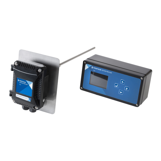
3 SYSTEM DESCRIPTION 3.1 COMPONENTS 3.1.1 FFA Sensor Figure 1: FFA sensor Standard sensor (max. 240°C) 3.1.2 FFA Control Unit Figure 2: FFA control unit See below for component descriptions. 1 Large display window (4:3 ratio) 2 Navigation keys (Up, Down, Right, ENTER) 3 M16 cable glands (3 off) 4 M20 cable gland (1 off) INSTALLATION AND OPERATION MANUAL –... -
Page 12: Overview
3.2 OVERVIEW The Filter Failure Alarm Monitor (FFA) is suitable for use after bag filters, cartridge filters, cyclones, and a range of other applications to ensure correct, expected filter performance. The FFA system comprises a sensor and a dedicated control unit. -
Page 13: Sensor Safety Description
4 SENSOR SAFETY DESCRIPTION 4.1 HAZARDOUS ZONES The sensor may be installed in a metal stack or duct containing hazardous dust, but the control unit must be installed in the designated Safe Area (see the Functional Diagram below). The control unit contains the power supply, alarm connections, and user controls. -
Page 14: Special Conditions Of Safe Use
4.2 SPECIAL CONDITIONS OF SAFE USE 4.2.1 Special Conditions of Safe Use for Sensor Enclosure, Body and Probe a) All connections to the equipment must not be inserted or removed unless the area in which the equipment is installed is known to be non-hazardous, or the circuit to which it is connected has been de-energized. This includes the plugging/unplugging of the screw terminals from the PCB-mounted headers. - Page 15 The FFA sensor unit has two labels applied to its enclosure: a serial number label and a label showing the ATEX-related Ex/CE marking obtained by the manufacturer for this instrument. ATEX DUST ZONE ZONE 22 Certificate number: PCME17ATEX0002X Outside stack (enclosure): Ex nA IIB T6 Gc Ex tc IIIC T80°C Dc Ta = –20°C to +50°C...
-
Page 16: Technical Data
5 TECHNICAL DATA 5.1 PROCESS AND APPLICATION CONDITIONS Stack temperature range –20 to 240°C (–4 to 465°F) SENSOR – KEY DATA Flue gas velocity >4 m/s Dust level response <1 to 500 mg/m³ (dependent upon application) Application conditions Suitable for measurement in non-condensing flue gases. Note: not recommended for deployment downstream of ESPs, or in applications with water droplets or mist at monitoring point. -
Page 17: Dimensioned Drawings - Sensor
5.2.2 Dimensional Drawings – Sensor INSTALLATION AND OPERATION MANUAL – OWNER'S RECORD FFA MANUAL – FILTER FAILURE ALARM... -
Page 18: Control Unit Specification
5.3 CONTROL UNIT SPECIFICATION FFA CONTROL UNIT Controller type FFA Controller Weight 1.2 kg (2.7 lb) Display 2.8″ colour LCD, 4:3 ratio ENCLOSURE Ambient temperature range –20 to +50°C (–4 to 120°F) Dimensions W 200 × H 124 x 81 mm (8 × 5 × 3.2 in.), incl. glands Protection rating IP66 Material... -
Page 19: Sensor Cable Specification
5.4.2 Sensor Cable Specification The minimum requirements are outlined in the following table. Cables supplied by Goyen | Mecair meet these requirements. Type 4-core (2-pair) cable Conductor size 0 5 mm² (16/0.2) Current rating 1 A r.m.s (max. per core) Working voltage max. -
Page 20: System Installation
6 SYSTEM INSTALLATION 6.1 SAFETY INFORMATION WARNING! – DANGER FROM PROCESS It is possible that the sensors are to be installed in ducting containing process particulate that is hazardous to health. Unless the process conditions are known to be entirely safe, suitable precautions such as the use of breathing apparatus or duct purging/detoxifying must be employed before any entry is made into the duct for installation or maintenance purposes. -
Page 21: Grounding The Sensor
Cables should be routed to avoid sources of large electromagnetic fields, such as heavy switching gear. Care taken during the installation of the cables ensures a long, maintenance-free life and avoids possible damage to the control unit and sensor. In summary, the cabling should be installed such that: Heavy vibration is minimized to prevent fatigue and failure. -
Page 22: Installing The Sensor
Where a cable run approaches the instrument from above, it must be run underneath the instrument and then • curved up to the cable gland. Where a cable enters a cable gland, sufficient slack should be left in the cable so that a new connection can •... -
Page 23: Fitting The Sensor To The Stack
6.3.2 Fitting the Sensor to the Stack Figure 4: Fitting the sensor to the stack 1 Sensor enclosure 2 Heat shield 3 Lock nut (30 mm A/F) 4 Insulator 5 Probe rod 6 Stack connection (threaded socket) 7 ½″ BSPP thread 8 Hexagonal sensor body (22 mm A/F) 9 Earth stud assembly (with grounding strap) 10 Breather... -
Page 24: Connecting The Sensor
6.4 CONNECTING THE SENSOR 6.4.1 Safety Information WARNING! Ensure the cabling is not connected to the control unit power during wiring. WARNING! – ELECTRIC SHOCK Ensure that only the cables types specified are used for powering and interconnection of equipment. 6.4.2 Sensor Connections Refer to Figure 5 below for the location of the terminals. -
Page 25: Setting Up The Sensor
6.5 SETTING UP THE SENSOR CAUTION! The enclosure cover lid and the cable glands must be tightened securely to provide an effective environmental seal. 6.5.1 Bus Termination Switch The bus termination switch is pre-set to T (terminated) ex works. 6.5.2 Communication Settings The sensor has fixed Comms settings. -
Page 26: Connecting The Control Unit
6.7 CONNECTING THE CONTROL UNIT Figure 7: Control unit PCB connections (inside enclosure lid) 1 Mains power terminals 2 Sensor connector (CN3) 3 Earth strap (do not remove) 4 Alarm relays/4–20 mAconnections (CN4) 5 Clamp (securing the mains power cable) 6.7.1 Connecting the Sensor Cable to the Control Unit NOTE: Keep the length of exposed screen to an absolute minimum (long screens, or ‘pigtails’, degrade EMC performance). -
Page 27: Connecting The Mains (Power) Supply
6.7.4 Connecting the Mains (Power) Supply WARNING! – ELECTRIC SHOCK Only connect to an earthed supply. This unit is a Class 1 construction and must be connected to a Protective Earth connection (GND). When wiring the mains cable, ensure that the earth wire is the longest one, so that if the cable is pulled out accidentally, the earth terminal disconnects last. -
Page 28: User Controls
7 USER CONTROLS 7.1 NAVIGATION Refer to Figure 2 on page 5 for the location of the user controls. Use the navigation and ENTER keys to select the required menu screen or function. UI CONTROL PURPOSE SYMBOL DESCRIPTION ENTER Press to select or confirm a menu option or code. NAVIGATION KEYS UP / DOWN Choose this menu option to select a setting or modify a digit. -
Page 29: Comms Check And Alarm Levels
7.2.1 Comms Check and Alarm Levels ICON MEANING LEVEL Green triangle. Communication with sensor has been established, no issues. COMMS (SENSOR/CONTROL UNIT) Communication with sensor has failed. Refer to Troubleshooting on page 31 for more information and solutions. No bell. Dust level readings are within the limits set. -
Page 30: Operation
8 OPERATION 8.1 BASIC FUNCTIONS 8.1.1 Entering the User PIN (Edit Settings) If you wish to protect your settings it is recommended to set and activate a User PIN, e.g. where the control unit is placed in areas with unrestricted access. For more information and instructions on Setting and Activating the User PIN see page 26. -
Page 31: User Menu - Settings Screen
8.1.2 User Menu – Settings Screen The basic settings are displayed in the order they are shown on the Settings screen: Figure 11: User Menu – Main Settings screen 1) SCALE 3) ALARM 2 (EARLY WARNING) 5) TIMER 2) SMOOTHING 4) ALARM 1 (HIGH ALARM) 6) SMOOTHING 4–20 mA 8.1.3 Changing Basic Settings... -
Page 32: Setting And Activating The User Pin
8.2.4 Setting and Activating the User PIN A two-digit User PIN should be set and activated to ensure that settings can only be changed by staff with the required credentials. However, it can be removed completely from the system using the master password (which must then be entered every time the PIN screen pops up). -
Page 33: Trimming The 4-20Ma Output
8.2.5 Trimming the 4–20 mA Output 1. On the Engineering screen, select option 3 (4 mA) or option 4 (20 mA) as required to display the trim screen. 2. Using the navigation buttons set the value required (see Changing Advanced Settings above for details). 3. -
Page 34: Maintenance
9 MAINTENANCE 9.1 SAFETY INFORMATION WARNING! Refer all servicing and maintenance to qualified service personnel. WARNING! – EXPLOSION OR COMBUSTION RISK Observe the requirements in the certificates, and the precautions and Special Conditions of Use documented in this manual. (See the Equipment Marking Information on page 8). The equipment may be opened only when it is de-energized or the area has been designated as ‘safe’... -
Page 35: Sensor Handling In Hazardous Areas
9.3 SENSOR HANDLING IN HAZARDOUS AREAS 9.3.1 Removing the Sensor from the Stack WARNING! – NON-ISOLATED EQUIPMENT Do NOT electrically disconnect the enclosure from the stack (i.e. break the ground/earth connection) in the presence of hazardous dusts. Circulating currents in the ground system could create an ignition hazard. -
Page 36: Cleaning The Control Unit
4. Check that the lock nut moves freely. 5. Apply a small amount of copper slip or grease to the threads to prevent binding. 6. Refit the sensor to the ductwork. 7. Inspect the connecting cable (where possible), ensuring that it is not damaged or stressed. 9.4.2 Cleaning the Control Unit The control unit requires minimal cleaning. -
Page 37: Troubleshooting
10 TROUBLESHOOTING 10.1 SAFETY INFORMATION WARNING! – NON-ISOLATED EQUIPMENT Do NOT electrically disconnect the enclosure from the stack (i.e. break the ground/earth connection) in the presence of hazardous dusts. Circulating currents in the ground system could create an ignition hazard. To disconnect the probe safely, remove the sensor from the stack, then disconnect the sensor from the power source or control unit by unplugging the connection wire at the control unit (in the Safe Area). -
Page 38: Figure 15: Checking Sensor Health
Figure 15: Checking sensor health 3. Remove the jumper, then wait for approximately 60 seconds to allow the sensor checks (zero, reference, contamination) to run. When the checks are complete, the health/alarm LED will either turn GREEN (tests passed) or RED (one or more tests failed). -
Page 39: General Notices
GENERAL NOTICES COMPLIANCE Electrical and Electronic Equipment Waste Directive (WEEE 2012/19/EU) This symbol, if marked on the product or its packaging, indicates that this product must not be disposed of with general household waste. In the European Union and many countries, separate collection systems have been set up to handle the recycling of electrical and electronic waste. - Page 40 NOTES INSTALLATION AND OPERATION MANUAL – OWNER'S RECORD FFA MANUAL – FILTER FAILURE ALARM...
- Page 41 NOTES INSTALLATION AND OPERATION MANUAL – OWNER'S RECORD FFA MANUAL – FILTER FAILURE ALARM...
- Page 42 NOTES INSTALLATION AND OPERATION MANUAL – OWNER'S RECORD FFA MANUAL – FILTER FAILURE ALARM...
- Page 43 NOTES INSTALLATION AND OPERATION MANUAL – OWNER'S RECORD FFA MANUAL – FILTER FAILURE ALARM...
- Page 44 CLEANAIRSYSTEMS.com © 2019 Pentair Clean Air Systems reserves the right to change product designs and specifications without notice.
Need help?
Do you have a question about the Goyen Mecair FFA and is the answer not in the manual?
Questions and answers