
Related Manuals for Pentair AUTOTROL MAGNUM 293


Summary of Contents for Pentair AUTOTROL MAGNUM 293
- Page 1 INSTALLER MANUAL AUTOTROL MAGNUM 293 - 298 LOGIX 742-762 INDUSTRIAL www.pentairaquaeurope.com...
-
Page 2: Table Of Contents
Installer manual Autotrol Magnum 293 - 298 Logix 742-762 - Table of Contents Table of Contents Generalities ..................Scope of the documentation ............... Release management ................. Manufacturer identifier, product ..............Abbreviations used ..................Norms......................1.5.1 Applicable norms ....................1.5.2 Available certificates................... - Page 3 Installer manual Autotrol Magnum 293 - 298 Logix 742-762 - Table of Contents Recommendations ..................29 4.1.1 Injector and Refill controller charts ..............4.1.2 Drain line flow control..................4.1.3 Recommended backwash flow rates for various media ........Cycle time calculation ................. 31 Injector flow rates ..................
- Page 4 Installer manual Autotrol Magnum 293 - 298 Logix 742-762 - Table of Contents 7.1.1 Activating the softener ..................7.1.2 Additional tips...................... Sanitization ....................65 7.2.1 Disinfection of water softeners................7.2.2 Sodium or calcium hypochlorite ................. 7.2.3 Electro chlorination..................... Operation..................67 Recommendations ..................
- Page 5 Installer manual Autotrol Magnum 293 - 298 Logix 742-762 - Table of Contents 10.3 Magnum valve cartridge................91 Spare parts..................93 11.1 Magnum Logix valve body ................93 11.2 Magnum connections .................. 94 11.3 Magnum Logix camshaft and pilot.............. 95 11.4...
-
Page 6: Generalities
Installer manual Autotrol Magnum 293 - 298 Logix 742-762 - Generalities Generalities Scope of the documentation The documentation provides the necessary information for appropriate use of the product. It informs the user to ensure efficient execution of the installation, operation or maintenance procedures. -
Page 7: Abbreviations Used
Installer manual Autotrol Magnum 293 - 298 Logix 742-762 - Generalities Abbreviations used BLFC Brine Line Flow Controller Down Flow DLFC Drain Line Flow Controller Injector Quick Connect Regen Regeneration Safety Brine Valve Time Clock Up Flow Norms 1.5.1 Applicable norms Comply with the following guidelines: •... -
Page 8: Procedure For Technical Support
Pentair Quality System EMEA products benefit, under specific conditions, from a manufacturer warranty that may be invoked by Pentair’s direct customers. Users should contact the vendor of this product for applicable conditions and in case of a potential warranty claim. - Page 9 Installer manual Autotrol Magnum 293 - 298 Logix 742-762 - Generalities • spare parts lists; • troubleshooting recommendations; • multi-lingual videos, detailing how to best service a part; • informations about new products, latest technologies, novelties about the Blue Network program, etc.
-
Page 10: Safety
Installer manual Autotrol Magnum 293 - 298 Logix 742-762 - Safety Safety Safety pictograms definition DANGER This combination of symbol and keyword indicates an imminently hazardous situation that will result in serious or fatal injury if not avoided. WARNING This combination of symbol and keyword indicates a potentially hazardous situation that can result in serious or fatal injury if not avoided. -
Page 11: Serial Label Location
Installer manual Autotrol Magnum 293 - 298 Logix 742-762 - Safety Serial label location Model Part number Electrical rating Serial number Production date Production order Mandatory Ensure that the serial label and the safety labels on the device are completely legible and clean ! -
Page 12: Hygiene And Sanitization
Installer manual Autotrol Magnum 293 - 298 Logix 742-762 - Safety Hygiene and sanitization 2.4.1 Sanitary issues Preliminary checks and storage • Check the integrity of the packaging. Check that there is no damage and no signs of contact with liquid to make sure that no external contamination occurred;... -
Page 13: Description
Installer manual Autotrol Magnum 293 - 298 Logix 742-762 - Description Description Introduction to the Magnum Cv and Magnum IT valves series The Magnum valve is available in several configurations: Magnum Cv Magnum IT Turbine External turbine Internal turbine Inlet diameter 3.91 cm (1 ½") -
Page 14: Technical Specifications
Installer manual Autotrol Magnum 293 - 298 Logix 742-762 - Description Technical specifications Design specifications/ratings Valve body PPO Glass fiber reinforced O-rings EPDM Weight (valve with controller) 10.6 kg Recommended operating pressure 1.72 - 6.9 bar Water temperature 1 - 38°C Ambient temperature* 2 - 50°C... -
Page 15: Performance Flow Rate Characteristics
Installer manual Autotrol Magnum 293 - 298 Logix 742-762 - Description Motor Input Voltage 12 VAC Controller Power Consumption 3 W average Protection rating IP23 Performance flow rate characteristics The graph shows the pressure drop created by the valve itself at different flow rates. It allows predetermining the maximum flow rate going through the valve depending on the system settings (inlet pressure etc). -
Page 16: Outline Drawing
Installer manual Autotrol Magnum 293 - 298 Logix 742-762 - Description Outline drawing Magnum Cv Magnum IT 16 / 110 Ref. MKT-IM-012 / D - 03.02.2022... -
Page 17: Components Description And Location
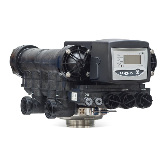
Installer manual Autotrol Magnum 293 - 298 Logix 742-762 - Description Components description and location Camshaft No hard water bypass valve cartidge Drain Optical sensor Outlet Inlet valve cartridge Motor Inlet LCD display Manual REGEN button UP button Pilot filter sreen... -
Page 18: Options Available On The Valve
Installer manual Autotrol Magnum 293 - 298 Logix 742-762 - Description Options available on the valve 3.6.1 6" flange plastic tank adapter This adapter allows a direct connection from the 6" flanged tank to the Magnum valve. It is manufactured from the same glass-filled thermoplastic as the Magnum valve body. -
Page 19: Refill First
Installer manual Autotrol Magnum 293 - 298 Logix 742-762 - Description 3.6.2 Refill first The Logix 742-762 controllers allow you to refill the brine tank first when used in softener mode. This feature allows the brine tank to be dry during the complete service cycle, reducing the caking phenomena. -
Page 20: Magnum Switch Kit
Installer manual Autotrol Magnum 293 - 298 Logix 742-762 - Description 3.6.4 Magnum switch kit Optional switch kits can be used on the Magnum Cv valve to provide electrical signalling capabilities. Used in conjunction with breakaway cams, the switches will provide a signal to external devices during the various cycles of the valve operations. - Page 21 Installer manual Autotrol Magnum 293 - 298 Logix 742-762 - Description Picture 1 Picture 2 Picture 3 Picture 4 Ref. MKT-IM-012 / D - 03.02.2022 21 / 110...
- Page 22 Installer manual Autotrol Magnum 293 - 298 Logix 742-762 - Description 3.6.4.2 Breakaway switch cam description The breakaway switch cam has been divided into 36 equal sections with each section representing approximately 10-degrees of the cam rotation. Each section is consecutively numbered 1 through 36 to aid in customized cam operating design.
- Page 23 Installer manual Autotrol Magnum 293 - 298 Logix 742-762 - Description 3.6.4.3 Breakaway switch cam instructions Based on the system requirements and the external devices used, determine the program timing, ie., when the external devices need to operate, either open or close.
- Page 24 Installer manual Autotrol Magnum 293 - 298 Logix 742-762 - Description Example : Picture 1 Removing sections 36 to 13 in a clockwise direction will provide an electrical signal during the slow rinse cycle. 10 degrees= 1 section Picture 2...
-
Page 25: Hydraulic Output Signal
Installer manual Autotrol Magnum 293 - 298 Logix 742-762 - Description 3.6.5 Hydraulic output signal An optional hydraulic output signal is available on the valve. An optional cam lobe on pilot valve #6 is used on the camshaft assembly to initiate the hydraulic output signal during regeneration or backwash. -
Page 26: Systems Regeneration Cycle
Installer manual Autotrol Magnum 293 - 298 Logix 742-762 - Description Systems regeneration cycle 3.7.1 298 Valves (5 - Cycle softener) Service (downflow) — cycle C0 Untreated water is directed down through the resin bed and up through the riser tube. The hardness ions attach themselves to the resin and are removed from the raw water being exchanged on the resin beads against sodium ions. - Page 27 Installer manual Autotrol Magnum 293 - 298 Logix 742-762 - Description Valve Valve SERVICE BACKWASH From brine tank Valve Valve BRINE/SLOW RINSE FAST RINSE C2 and C3 To brine tank Valve BRINE REFILL Ref. MKT-IM-012 / D - 03.02.2022 27 / 110...
-
Page 28: Valves (3 - Cycle Filter)
Installer manual Autotrol Magnum 293 - 298 Logix 742-762 - Description 3.7.2 293 Valves (3 - Cycle filter) Service — cycle C0 Untreated water is direct down through the conditioning media and up through the riser tube, then out to the system. -
Page 29: System Sizing
Installer manual Autotrol Magnum 293 - 298 Logix 742-762 - System sizing System sizing Recommendations 4.1.1 Injector and Refill controller charts Vessel diameter [In] Injector Flow control Refill flow control Backwash flow control [gpm] [gpm] [gpm] 10.0 14.0 21.0 30.0 Info All flow rates are based on an inlet pressure of 413 kPA. -
Page 30: Recommended Backwash Flow Rates For Various Media
Installer manual Autotrol Magnum 293 - 298 Logix 742-762 - System sizing Flow control disc Insert 1 Insert 2 Insert 3 Insert 4 [gpm] 4.994 Green Green Black 5.221 Green Green Brown Black 5.448 5.675 Green Green White Black 5.902... -
Page 31: Cycle Time Calculation
Installer manual Autotrol Magnum 293 - 298 Logix 742-762 - System sizing Media Tank diameter 14" 16" 18" 21" 24" 30" 36" (35.6 cm) (40.6 cm) (45.7 cm) (53.3 cm) (61.0 cm) (76.2 cm) (91.4 cm) Tank Tank Tank Tank Tank Tank Tank Multi Layer (15 gpm/ft (36.75 m/h/cm... - Page 32 Installer manual Autotrol Magnum 293 - 298 Logix 742-762 - System sizing BRINE DRAW TOTAL RINSE Injector 1000441 Injector 1000442 For 14" Tanks For 16" Tanks Inlet pressure [bar] Inlet pressure [bar] Injector 1000443 Injector 1000444 For 18" Tanks For 21" Tanks...
-
Page 33: Standard Efficiency Exchange Capacity
Installer manual Autotrol Magnum 293 - 298 Logix 742-762 - System sizing BRINE DRAW TOTAL RINSE Injector 1000445 Injector 1000446 For 24" Tanks For 30" Tanks Inlet pressure [bar] Inlet pressure [bar] Injector 1000447 For 36" Tanks Inlet pressure [bar]... - Page 34 Installer manual Autotrol Magnum 293 - 298 Logix 742-762 - System sizing Salt [grams/liter] Exchange capacity [grams/liter] 50.2 52.1 53.8 55.5 58.5 62.7 66.9 75.3 34 / 110 Ref. MKT-IM-012 / D - 03.02.2022...
-
Page 35: Installation
Installer manual Autotrol Magnum 293 - 298 Logix 742-762 - Installation Installation Safety notices for installation • Observe all warnings that appear in this manual; • only qualified and professional personnel are authorized to carry out installation work. Installation environement 5.2.1... -
Page 36: Mechanical
Installer manual Autotrol Magnum 293 - 298 Logix 742-762 - Installation 5.2.3 Mechanical Caution - material Risk of damage due to wrong lubricant use ! Do not use petroleum-based lubricants such as vaseline, oils, or hydrocarbon-based lubricants. Use only approved silicone grease or soapy water ! •... -
Page 37: Integration Constraints
Installer manual Autotrol Magnum 293 - 298 Logix 742-762 - Installation • temperature — Extreme hot or cold temperatures may cause damage to the valve or controller. Freezing temperatures will freeze the water in the valve. This will cause physical damage to the internal parts as well as the plumbing. -
Page 38: Block Diagram And Configuration Example
Installer manual Autotrol Magnum 293 - 298 Logix 742-762 - Installation Block diagram and configuration example Block diagram Pressure gauge Main inlet User’s line Check valve to prevent water harm Filter cartridge Pressure regulator By-pass Suggested options Meter Drain line... - Page 39 Installer manual Autotrol Magnum 293 - 298 Logix 742-762 - Installation Inlet valve Outlet valve Drain line flow control Drain Manual bypass valve Logix controller Turbine 1.5" Riser tube Brine line Hub & Lateral Brine tank Magnum Cv Configuration example Magnum IT Ref.
-
Page 40: Valve Connection To Piping
Installer manual Autotrol Magnum 293 - 298 Logix 742-762 - Installation Valve connection to piping The connections should be hand tightened using PTFE (plumber’s tape) on the threads if using the threaded connection type. In case of heat welding (metal type connection), the connections should not be made to the valve when soldering. - Page 41 Installer manual Autotrol Magnum 293 - 298 Logix 742-762 - Installation • failure to provide enough vertical compensation may lead to different kinds of damage, either on the valve thread which is connected to the tank, or on the female thread connection of the tank.
-
Page 42: Side-Mounted Valve Installation
Installer manual Autotrol Magnum 293 - 298 Logix 742-762 - Installation 5.5.2 Side-mounted valve installation Use a 2" BSP side mount adapter assembly for the installation. Side mount adapter • valid for location having a reduced height; • to avoid the piping supporting the valve and side adapter weight, they must be fixed on a tripod or any other appropriate support;... -
Page 43: Connections (Electrical)
Installer manual Autotrol Magnum 293 - 298 Logix 742-762 - Installation Connections (electrical) Lockout connection (764 only) Chlorine generator outlet (EU versions only) AC transformer input (low voltage) Main motor & optical sensor connection Sensor input for turbine 760/762 Dry contact signal input 740/742... -
Page 44: Drain Line Connection
Installer manual Autotrol Magnum 293 - 298 Logix 742-762 - Installation Caution - material Risk of damage due to bad mounting ! Do not solder pipes with lead-based solder. Do not use tools to tighten plastic fittings. Over time, stress may break the connections. -
Page 45: Overflow Line Connection
Installer manual Autotrol Magnum 293 - 298 Logix 742-762 - Installation Air gap Drain Overflow line connection In the event of a malfunction, the brine tank overflow fitting will direct “overflow” to the drain instead of spilling on the floor. This fitting should be on the side of the brine tank. Most brine tank manufacturers feature a pre-drilled hole for the tank overflow connector. -
Page 46: Programming
Installer manual Autotrol Magnum 293 - 298 Logix 742-762 - Programming Programming Display Hourglass Displayed when the motor is running. The camshaft should be turning. Cursor These cursors appear next to the item that is currently displayed. Days of the week Displayed days of the week. - Page 47 Installer manual Autotrol Magnum 293 - 298 Logix 742-762 - Programming "PM" Indicates that the time displayed is between 12:00 noon and 12:00 midnight. "PM" indicator is not used if the clock mode is set to 24-hour (there is no AM indicator).
-
Page 48: Commands
Installer manual Autotrol Magnum 293 - 298 Logix 742-762 - Programming Commands Used to scroll down or decrement through a group of choices. - Down arrow Used to accept a setting that normally becomes stored in - Set memory. Also used together with the arrow buttons to access special features. -
Page 49: Basic Programming
Installer manual Autotrol Magnum 293 - 298 Logix 742-762 - Programming Basic programming Info Menus are displayed in a defined and incremental order. 6.3.1 Basic programming mode chart 742-762/298 valve type Parameter Range of Default Units of Notes description values... -
Page 50: Basic Programming Mode Chart 742F-762F/293 Valve Type
Installer manual Autotrol Magnum 293 - 298 Logix 742-762 - Programming 6.3.2 Basic programming mode chart 742F-762F/293 valve type Parameter Range of Default Units of Notes description values value measure Program valve 255, 263, 268, None type 278 and Magnum series... -
Page 51: Basic Programming 742 - 762/298 Valve Type
Installer manual Autotrol Magnum 293 - 298 Logix 742-762 - Programming 6.3.3 Basic programming 742 - 762/298 valve type 6.3.3.1 Program valve type Set your valve type through the options. 1. Use to scroll though valve type choices. ð Valve type flashes 2. - Page 52 Installer manual Autotrol Magnum 293 - 298 Logix 742-762 - Programming 6.3.3.5 Regeneration time Set the time when regeneration will take place. 1. Press ð Regeneration time flashes. 2. Adjust displayed time with ð Default setting: 2:00am. 3. Press to validate the selection and advance to the next parameter using 6.3.3.6...
- Page 53 Installer manual Autotrol Magnum 293 - 298 Logix 742-762 - Programming 6.3.3.9 Estimated capacity Info Note The system capacity is displayed in kilograms equivalent CaCO of hardness removed before a regeneration is necessary. The system capacity is calculated by the Logix software, using the resin volume, brine dosage and hardness settings.
-
Page 54: Basic Programming 742F - 762F/293 Valve Type
Installer manual Autotrol Magnum 293 - 298 Logix 742-762 - Programming 6.3.4 Basic programming 742F - 762F/293 valve type 6.3.4.1 Program valve type Set your valve type through the options. 1. Use to scroll though valve type choices. ð Valve type flashes 2. - Page 55 Installer manual Autotrol Magnum 293 - 298 Logix 742-762 - Programming 6.3.4.5 Time of backwash Set the time of backwash cycle (C1). 1. Press ð Backwash time flashes. 2. Adjust displayed time with 3. Press to validate the selection and advance to the next parameter using 6.3.4.6...
-
Page 56: Advanced Programming
Installer manual Autotrol Magnum 293 - 298 Logix 742-762 - Programming Advanced programming Info Press and hold for 5 seconds to access advance programming. A "P" symbol is displayed on the bottom left of screen 6.4.1 Basic programming parameters (5 - Cycle softener system) -
Page 57: Advanced Programming Parameters (5 - Cycle Softener System)
Installer manual Autotrol Magnum 293 - 298 Logix 742-762 - Programming 6.4.2 Advanced programming parameters (5 - Cycle softener system) Parameter Range of Default Units of Notes description values value measure P9 Units of measure 0 - 1 0 = US unit. -
Page 58: Basic Programming Parameters (3 - Cycle Filter System)
Installer manual Autotrol Magnum 293 - 298 Logix 742-762 - Programming Info Parameters P16 to P19 are skipped on 742 controller. 6.4.3 Basic programming parameters (3 - Cycle filter system) Parameter Range of Default Units of Notes description values value... - Page 59 Installer manual Autotrol Magnum 293 - 298 Logix 742-762 - Programming Parameter Range of Default Units of Notes description values value measure Remote 3 - 250 Second Time remote switch must be regeneration active to start regeneration on 742 controller.
-
Page 60: Cycle Time Programming
Installer manual Autotrol Magnum 293 - 298 Logix 742-762 - Programming 6.4.5 Cycle time programming Set the cycle time programming. 1. Press and hold the and for 5 seconds when the controller is not in regeneration to enter cycle time programming. -
Page 61: Diagnostic
Installer manual Autotrol Magnum 293 - 298 Logix 742-762 - Programming 6.4.6 Diagnostic To access diagnostic values, press and hold for 5 seconds to view the "H" levels. Diagnosti Description Unit Range c Code Initial setting value Litre Resin Volume... -
Page 62: Resetting The Controller
Installer manual Autotrol Magnum 293 - 298 Logix 742-762 - Programming 6.4.7 Resetting the controller Info Resetting the controller will delete all information stored in its memory, except the time and day. This will require you to reprogram the controller completely from the initial power-up mode. -
Page 63: Commissioning
Installer manual Autotrol Magnum 293 - 298 Logix 742-762 - Commissioning Commissioning Info This chapter is available for standard regeneration flows. Contact your supplier if the actual regeneration is not standard and if you need assistance. Water filling, draining and waterproofness inspection 7.1.1... - Page 64 25 mm (1") above the platform. Info Pentair recommends that recommend that you do not put salt into the tank before the control valve has been started up. With no salt in the tank, it is much easier to view water flow and motion.
-
Page 65: Additional Tips
Installer manual Autotrol Magnum 293 - 298 Logix 742-762 - Commissioning 7.1.2 Additional tips • When the controller is first plugged in, it may display a flashing hourglass and the message "Err 3", this means that the controller is rotating to the home position. If the "Err 2" is displayed, check that the incoming power frequency matches the controller;... -
Page 66: Electro Chlorination
Installer manual Autotrol Magnum 293 - 298 Logix 742-762 - Commissioning Brine tank softeners Backwash the softener and add the required amount of hypochlorite solution to the well of the brine tank. The brine tank should have water in it to permit the solution to be carried into the softener. -
Page 67: Operation
Installer manual Autotrol Magnum 293 - 298 Logix 742-762 - Operation Operation During a regeneration: • A "C#" is displayed to show the current cycle; • total regen time remaining is displayed on screen; • you can press and hold to show current cycle time remaining. -
Page 68: To Advance Regeneration Cycles
Installer manual Autotrol Magnum 293 - 298 Logix 742-762 - Operation Double regeneration 1. After an immediate regeneration has begun, press again to plan a second manual regeneration. ð A flashing "x2" symbol indicates the second regeneration will start at the programmed delayed regeneration time. -
Page 69: Maintenance
Installer manual Autotrol Magnum 293 - 298 Logix 742-762 - Maintenance Maintenance Mandatory Cleaning and maintenance shall take place at regular intervals in order to guarantee the proper functioning of the complete system, and be documented in the Maintenance chapter in the User Guide document. -
Page 70: Regeneration Test
Installer manual Autotrol Magnum 293 - 298 Logix 742-762 - Maintenance 9.1.3 Regeneration test 1. Initiate manual regeneration and overserve flow to drain. 2. Make sure flow rate correspond to DLFC configuration. 3. Check for media loss at the drain during backwash. -
Page 71: Cv / It: General System Inspection
Installer manual Autotrol Magnum 293 - 298 Logix 742-762 - Maintenance Items 1 year 2 year 3 year 4 year 5 year External Check / clean Check / clean Check / clean Check / clean Replace Turbine (Cv model, if present)*** Turbine cable Check... -
Page 72: Regeneration Test
Installer manual Autotrol Magnum 293 - 298 Logix 742-762 - Maintenance 6. If pressure gauges are installed before and after softening system, verify and record static and dynamic pressure, reporting pressure drop. Verify that inlet pressure respects valve and softening system limits. Make sure dynamic pressure always remain above 1.78 bar to ensure proper Magnum valve function. - Page 73 Installer manual Autotrol Magnum 293 - 298 Logix 742-762 - Maintenance Items 1 year 2 year 3 year 4 year 5 year Motor, motor Check Check Check Check Replace cable and optical sensor harness Optical sensor Check Check Check Check Replace Electronic /...
-
Page 74: Recommendations
Installer manual Autotrol Magnum 293 - 298 Logix 742-762 - Maintenance Recommendations 9.5.1 Use original spare parts Caution - material Risk of damage due to use of non-genuine spare parts ! To ensure correct operation and safety of the device, only use original spare parts and accessories recommended by the manufacturer. -
Page 75: Cleaning And Maintenance
Installer manual Autotrol Magnum 293 - 298 Logix 742-762 - Maintenance Cleaning and maintenance 9.6.1 First steps Before any cleaning or maintenance procedure, complete the following steps: Mandatory These operations must be performed before any cleaning or maintenance procedure ! 1. Unplug the wall-mounted transformer. - Page 76 Installer manual Autotrol Magnum 293 - 298 Logix 742-762 - Maintenance 76 / 110 Ref. MKT-IM-012 / D - 03.02.2022...
-
Page 77: Pilot Filter Screen Cleaning
Installer manual Autotrol Magnum 293 - 298 Logix 742-762 - Maintenance 9.6.4 Pilot filter screen cleaning 1. Using a Torx key, unscrew and extract the injector screen cap (1). 2. Unclip the white plastic basket and clean it with a soft brush.Use of descaling agent such as white vinegar might be required in case of impurities on the plastic basket (2). -
Page 78: Controller Cover Disassembly
Installer manual Autotrol Magnum 293 - 298 Logix 742-762 - Maintenance 9.6.5 Controller cover disassembly 1. Unlock the controller cover from the slide clips (one on each side of the valve). 2. Pull straight off the controller cover (1). 3. Reverse above procedure steps to rebuild. -
Page 79: Motor Replacement
Installer manual Autotrol Magnum 293 - 298 Logix 742-762 - Maintenance 9.6.7 Motor replacement 1. Remove the controller cover (1). See Controller cover disassembly [ Page 78]. → 2. Press the controller locking pad (4) and slide the controller out of its position. -
Page 80: Camshaft Replacement
Installer manual Autotrol Magnum 293 - 298 Logix 742-762 - Maintenance 9.6.8 Camshaft replacement 1. Remove the camshaft cover (1). See Camshaft cover disassembly [ Page 78]. → 2. Press on the release tab and pull on the back end of the camshaft (2). -
Page 81: Optical Sensor And Controller Replacement
Installer manual Autotrol Magnum 293 - 298 Logix 742-762 - Maintenance 9.6.9 Optical sensor and controller replacement 1. Remove the controller cover (1). See Controller cover disassembly [ Page 78]. → 2. Press the controller locking pad and slide the controller out of its position. -
Page 82: Turbine Cleaning Or Replacement
Installer manual Autotrol Magnum 293 - 298 Logix 742-762 - Maintenance 9.6.10 Turbine cleaning or replacement Info Depending on the valve installation, the turbine may not be present in the valve. (Magnum IT : internal turbine/Magnum Cv : external turbine). -
Page 83: Top Plate And Disc Valve Replacement
Installer manual Autotrol Magnum 293 - 298 Logix 742-762 - Maintenance 9.6.11 Top plate and disc valve replacement 1. Remove the camshaft cover. See Camshaft cover disassembly [ Page 78]. → 2. Remove the camshaft. See Camshaft replacement [ Page 80]. →... - Page 84 Installer manual Autotrol Magnum 293 - 298 Logix 742-762 - Maintenance 84 / 110 Ref. MKT-IM-012 / D - 03.02.2022...
-
Page 85: Cartridge Replacement
Installer manual Autotrol Magnum 293 - 298 Logix 742-762 - Maintenance 9.6.12 Cartridge replacement Info Removal of cartridges should be done only after reviewing all other possible causes of problem (see Magnum valve cartridge [ → Page 91]). Info There may be some difficulties to remove cartridges in valves that have been in service for a long period of time. - Page 86 Installer manual Autotrol Magnum 293 - 298 Logix 742-762 - Maintenance 86 / 110 Ref. MKT-IM-012 / D - 03.02.2022...
-
Page 87: Valve On Tank Assembly
Installer manual Autotrol Magnum 293 - 298 Logix 742-762 - Maintenance 9.6.13 Valve on tank assembly 1. Lubricate the seals with approved silicone grease. 2. Spin the valve (1) onto the tank (2), ensuring the threads are not cross-threaded. 3. Rotate the valve (1) clockwise and freely, without using force until it comes to a stop. -
Page 88: Troubleshooting
Installer manual Autotrol Magnum 293 - 298 Logix 742-762 - Troubleshooting Troubleshooting 10.1 Logix controller Err. code Cause Solution ERR 1 Controller power has been connected Reset controller. and the controller is not sure of the See Resetting the controller operating status. -
Page 89: Magnum It And Cv Valve
Installer manual Autotrol Magnum 293 - 298 Logix 742-762 - Troubleshooting Err. code Cause Solution ERR3 Camshaft rotates for more than If motor keeps rotating indefinitely, 5 minutes to find Home position. replace the following components in this order: • Wire harness. - Page 90 Installer manual Autotrol Magnum 293 - 298 Logix 742-762 - Troubleshooting Issue Cause Solution No brine draw. Plugged injector and/or injector • Inspect and clean the injector screen. and/ or injector screen assembly. Insufficient water pressure. • Increase water pressure above 172 kPa minimum.
-
Page 91: Magnum Valve Cartridge
Installer manual Autotrol Magnum 293 - 298 Logix 742-762 - Troubleshooting Issue Cause Solution Loss of water Fouled resin bed due to iron • Clean Magnum control valve and pressure. accumulation. mineral bed with cleaner. Slots in riser pipe or laterals are filled •... - Page 92 Installer manual Autotrol Magnum 293 - 298 Logix 742-762 - Troubleshooting 1. A constant leak from the pilot drain in any cycle position. A small discharge of water from the pilot drain while transitioning from one cycle to the next is normal.
-
Page 93: Spare Parts
Installer manual Autotrol Magnum 293 - 298 Logix 742-762 - Spare parts Spare parts 11.1 Magnum Logix valve body Item Part number Description Assembly quantity 3007801 Magnum Cv valve body cartridges, HWB / UWB, Magnum Logix single camshaft 3007803 Magnum Cv valve body cartridges, NHB / NUB, Magnum Logix... -
Page 94: Magnum Connections
Installer manual Autotrol Magnum 293 - 298 Logix 742-762 - Spare parts 11.2 Magnum connections Item Part number Description Assembly quantity 1001655 Magnum Cv 1 ½" - 1 ½" PVC adapter kit 1001656 Magnum Cv 1 ½" - 50 mm PVC adapter kit 3023674 Magnum IT/Cv plus 2"... -
Page 95: Magnum Logix Camshaft And Pilot
Installer manual Autotrol Magnum 293 - 298 Logix 742-762 - Spare parts 11.3 Magnum Logix camshaft and pilot Item Part number Description Assembly quantity 1000589 Pillow block cap 1267726 Camshaft logix Magnum single tank 1000341 Shaft, cam, Magnum 1000339 Top plate... -
Page 96: Magnum Refill Controller Assembly
Installer manual Autotrol Magnum 293 - 298 Logix 742-762 - Spare parts 11.4 Magnum refill controller assembly Item Part number Description Assembly quantity 1040688 Flow controller plug 1041687 Refill controller assembly 1000421 Refill flow controller for 14" tank - 0.7 gpm (0.16 m 1000422 Refill flow controller for 16"... -
Page 97: Magnum Injector Assembly
Installer manual Autotrol Magnum 293 - 298 Logix 742-762 - Spare parts 11.5 Magnum injector assembly Item Part number Description Assembly quantity 1040670 Injector for 14" tank with O-rings - 0.5 gpm (0.11 m 1040671 Injector for 16" tank with O-rings - 0.5 gpm (0.11 m 1040672 Injector for 18"... -
Page 98: Magnum Drain Line Flow Controls Assembly
Installer manual Autotrol Magnum 293 - 298 Logix 742-762 - Spare parts 11.6 Magnum drain line flow controls assembly Item Part number Description Assembly quantity 1040720 Assembled DLFC without O-ring and flow controls Inserts 5 gpm (1.14 m /h) (for 14" softener) BLU-BLK-BLK-BLK... - Page 99 Installer manual Autotrol Magnum 293 - 298 Logix 742-762 - Spare parts Item Part number Description Assembly quantity 1040743 Assembled DLFC without O-ring and flow controls Inserts 18 gpm (4.09 m /h) WHI-WHI-BLK-BLK 1040744 Assembled DLFC without O-ring and flow controls Inserts 19 gpm (4.31 m...
- Page 100 Installer manual Autotrol Magnum 293 - 298 Logix 742-762 - Spare parts Item Part number Description Assembly quantity 1040753 Assembled DLFC without O-ring and flow controls Inserts 38 gpm (8.63 m /h) ORA-ORA-ORA-GRN 1040754 Assembled DLFC without O-ring and flow controls Inserts 39 gpm (8.86 m...
-
Page 101: Magnum Cartridges
Installer manual Autotrol Magnum 293 - 298 Logix 742-762 - Spare parts 11.7 Magnum cartridges #4 Inlet Cartridge Rinse valve Drain valve cartridge cartridge #3 Outlet Cartridge No hard water Hard water bypass valve bypass cap cartridge #2 Rinse #1 Drain... -
Page 102: Magnum Logix Controllers
Installer manual Autotrol Magnum 293 - 298 Logix 742-762 - Spare parts 11.8 Magnum Logix controllers Item Part number Description Assembly quantity 1265832 Timer Logix 742F Magnum 1265833 Timer Logix 762F Magnum 1265834 Timer Logix 742 Magnum 1265835 Timer Logix 762 Magnum... -
Page 103: Magnum It Turbine
Installer manual Autotrol Magnum 293 - 298 Logix 742-762 - Spare parts Item Part number Description Assembly quantity 5+6+7 1233809 Logix Magnum controller mechanical assembly (items #5, 6, +8+9 7, 8, 9, 10, 12) 1000813 Wall mount transformer 220 V/12 V UK... -
Page 104: 2" External Turbine Assembly
Installer manual Autotrol Magnum 293 - 298 Logix 742-762 - Spare parts 11.10 2" external turbine assembly Item Part number Description Assembly quantity 1033358 2" turbine only 3023537 2" turbine assembly with 2" stainless steel BSP adapters 1034080 2" turbine assembly with 2" PVC adapters 1034081 2"... -
Page 105: Magnum Miscellaneous
Installer manual Autotrol Magnum 293 - 298 Logix 742-762 - Spare parts 11.12 Magnum miscellaneous External pilot feed adapter Switch kit Pilot filter screen assembly Pilot system check valves Item Part number Description Assembly quantity 3019468 Kit 1 switch 0.1 Amp... -
Page 106: Magnum 298 Installation Components
Installer manual Autotrol Magnum 293 - 298 Logix 742-762 - Spare parts 11.13 Magnum 298 installation components Item Part number Description Assembly quantity Drain line flow control (refer to DLFC list, see chapter 11.6. Magnum drain line flow controls assembly, page 95) -
Page 107: Magnum 293 Installation Components
Installer manual Autotrol Magnum 293 - 298 Logix 742-762 - Spare parts 11.14 Magnum 293 installation components Item Part number Description Assembly quantity Drain line flow control (refer to DLFC list, see chapter 11.6. Magnum drain line flow controls assembly, page 95) -
Page 108: Disposal
This will help to reduce the impact on the environment, health, safety and help to promote recycling. Pentair does not collect used product for recycling. Contact your local recycling center for more information. - Page 109 Installer manual Autotrol Magnum 293 - 298 Logix 742-762 Notes Ref. MKT-IM-012 / D - 03.02.2022 109 / 110...
- Page 110 All indicated Pentair trademarks and logos are property of Pentair. Third party registered and unregistered trademarks and logos are the property of their respective owners. © 2022 Pentair. All rights reserved.
Need help?
Do you have a question about the AUTOTROL MAGNUM 293 and is the answer not in the manual?
Questions and answers