
Related Manuals for Pentair Goyen Precision P1


Summary of Contents for Pentair Goyen Precision P1
- Page 1 PRECISION ® FILTER CLEANING SYSTEM CONTROLS PENTAIR CLEAN AIR SYSTEMS INSTALLATION AND OPERATING INSTRUCTIONS...
-
Page 2: Table Of Contents
© Copyright by Pentair International Ltd. 2014 This manual is provided as an aid to owners of a Pentair Clean Air Systems instrument and contains information proprietary to Pentair Clean Air Systems. This manual may not, in whole or part, be copied, or reproduced without the express written consent of Pentair Clean Air Systems. -
Page 3: Warning
WARNING To avoid product malfunction or electrical shock, do not expose Precision circuit boards to rain or moisture. Installation must be performed using qualified technicians. CAUTION Use of controls or adjustments or performance or procedures other than those specified in this manual may result in product failure, or poor product performance. -
Page 4: Identifying.the.parts
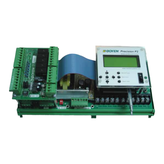
IDENTIFYING THE PARTS Your system may have some or all of these components. Note that terminal headers are supplied for all push-in contacts. Figure 1: P1.Interface.and.Controller,.Top.View. Figure 2: Controller,.Front.View DIRTY CLEAN Note: Controller assemblies in Figures 1 and 2 include (left to right) P-CTX, P-MOD and P2 interface, all mounted on the AC/AC baseboard. - Page 5 Figure 4: PS-L,.DC.Output.Large.Terminal.Expansion.Card Key.to.Figures.1.to.7. Precision motherboard (10 output) P2 Enhanced Demand Mode interface P1 Sequential Mode interface Power-on switch Power LED Motherboard manual solenoid triggers and LEDs. Motherboard solenoid terminals P-MOD, Modbus card (optional) Figure 5: AC/AC.Baseboard.Top.View P-CTX, I/O card (optional) Power in Expansion card connection Fan contacts...
-
Page 6: Installation.-.General
INSTALLATION GENERAL MECHANICAL The Precision may be supplied as PCB only, in 316 stainless steel IP65 (Nema 4) enclosures, or in painted steel IP65 (Nema 4) enclosures. General. Install Precision in areas of minimal vibration. • Install in an area free from high electrical noise or interference. •... - Page 7 The Precision baseboard has ten outputs. A further 190 outputs may be added in increments of 10 by serial connection • (19 maximum expansion cards per baseboard) by either PS-C and PS-L terminal expansion boards connected to AC/DC or DC/DC baseboards, and PS-CA and PS-LA connected to AC/AC baseboards. PS-C, PS-L expansion cards, AC/DC and DC/DC baseboards have 24 V DC output at each terminal, each capable of powering •...
- Page 8 Figure 8: Wiring.Diagram.for.the.AC/DC.and.DC/DC.Baseboard.with.P-CTX.(CTX.Card),.P-MOD.(Modbus),.Expansion.Cards. and.Tube.Cleaner INSTALLATION AND OPERATING INSTRUCTIONS PRECISION FILTER CLEANING SYSTEM CONTROLS ®...
- Page 9 Figure 9: Wiring.Diagram.for.the.AC/AC.Baseboard.with.P-CTX.(CTX.Card),.(P-MOD).Modbus,.P1.and.P2.Option INSTALLATION AND OPERATING INSTRUCTIONS PRECISION FILTER CLEANING SYSTEM CONTROLS ®...
- Page 10 Figure 10: Wiring.Diagram.for.Compact.Expansion.Cards.on.the.AC/AC.Baseboard INSTALLATION AND OPERATING INSTRUCTIONS PRECISION FILTER CLEANING SYSTEM CONTROLS ®...
- Page 11 Figure 11: Wiring.Diagram.for.Large.Expansion.Cards.on.the.AC/AC.Baseboard INSTALLATION AND OPERATING INSTRUCTIONS PRECISION FILTER CLEANING SYSTEM CONTROLS ®...
-
Page 12: Installation.-.Optional.accessories
INSTALLATION OPTIONAL ACCESSORIES 10 11 12 13 14 15 P-CTX: I/O CARD Figure 12: P-CTX Key.to.Figure.12 DESCRIPTION TYPE DETAILS Fuse 4–20 mA differential pressure output GND Output Ground Output 24 VDC Output 0 VDC Cycling Output Voltage free Remote indication of when a valve is being actuated. Common Voltage free Watchdog alarm... -
Page 13: P-Mod: Modbus Communications Card
BASIC INFORMATION The P-CTX card provides voltage-free contacts for alarm outputs, basic remote control inputs and a 4–20 mA output for differential pressure reporting (P2 only). Figure 2 shows the P-CTX mounted correctly on the left side of the baseboard. The table on page 12 provides a description of each I/O point, which may be connected to remote push-buttons, lights, sirens, data-loggers, control panels and programmable logic controllers. -
Page 14: Operation
OPERATION POWERING UP THE SYSTEM See Figure 1 (items 4 and 5). Moving the power switch into the on position will power up the Precision. The Power LED will light, and the backlit interface display will light up. The Precision performs a self-diagnostic routine, confirming all attached modules and reporting automatically all attached solenoids and expansion cards. -
Page 15: Programming.and.advanced.features
PROGRAMMING AND ADVANCED FEATURES To enter programming mode, press Enter (Figure 14, item 6), followed by: + − − + Enter UP (Figure 14, item 2), scroll to previous menu item; DOWN (Figure 14, item 3), scroll to next menu item. P1 –... -
Page 16: P2 - Enhanced Demand Control
Tube.Cleaner. Available on the AC/AC baseboard, otherwise only when P-CTX is fitted. This allows the tube-cleaning parameters to be specified: Select ON or OFF, then: Period: The frequency of the tube-cleaning pulse. 1 to 999 minutes. Duration: The duration of the tube-cleaning pulse. 1 to 60 seconds. This feature is used to control the pulse cleaning of the differential pressure-sensing lines. - Page 17 DESCRIPTION OF MENU ITEMS (P2 SPECIFIC) Display.Units. Allows the display units for pressure to be set to one of five commonly used measures. See table above. The selected units will then be used for all differential pressure-related settings, and network reporting via P-MOD. Demand.Cleaning.
-
Page 18: Messages.and.alarms
MESSAGES AND ALARMS MESSAGES Scrolling.Display DISPLAY DESCRIPTION Model xx.xx Software version number Continuous Mode Controller is in Continuous Mode Demand Mode Controller is in Demand Mode On Time = xxx ms Electrical On Time of Solenoid Off Time = xxx sec Electrical Off Time of Solenoid Slaves = xxxx Number of Slaves connected to Controller... - Page 19 Alarm.Messages DISPLAY DESCRIPTION Coil OC Fail – xx:yy* Coil yy on Slave xx has failed Open Circuit – Replace coil. Coil CC Fail – xx.yy* Coil yy on Slave xx has failed Closed Circuit – Replace coil. Low Coil Voltage – xx.yy Voltage outside the recommended voltage is being delivered to the coil yy on Slave xx or to the baseboard –...
-
Page 20: Troubleshooting
TROUBLESHOOTING The Precision is programmed with system self-diagnostics. Most issues can be resolved by reference to the system messages and alarms present on the interface and listed in the previous section, ‘Messages and Alarms’. For issues which cannot be resolved in this way, refer to the table below or contact your system supplier. General/Startup. -
Page 21: Operational
Operational SYMPTOM CAUSE RESOLUTION P2 does not go into cleaning mode on P2 is waiting for differential pressure to rise Enter the menu and set Precoating to off, or startup. Display shows: ‘Precoating’. above the factory preset Precoating value wait for differential pressure to rise. Valves do not pulse. -
Page 22: Precision.system.specifications
PRECISION SYSTEM SPECIFICATIONS ELEMENT DETAILS P2 on-board pressure transducer Operating Pressure Range: 0 to 2.5 kPa (0 to 10″ WG) Accuracy: +/−2.5% FSS Burst pressure: 20 kPa (83″ WG) Vibration resistance: to 10 G at 20–2000 Hz Response time: 8 ms Temperature-compensated ASIC signal conditioning DC/DC baseboard Input voltage: 24 to 48 V DC (+/−10%) - Page 23 INSTALLATION AND OPERATING INSTRUCTIONS PRECISION FILTER CLEANING SYSTEM CONTROLS ®...
- Page 24 INSTALLATION AND OPERATING INSTRUCTIONS PRECISION FILTER CLEANING SYSTEM CONTROLS ®...
- Page 25 INSTALLATION AND OPERATING INSTRUCTIONS PRECISION FILTER CLEANING SYSTEM CONTROLS ®...
- Page 26 INSTALLATION AND OPERATING INSTRUCTIONS PRECISION FILTER CLEANING SYSTEM CONTROLS ®...
- Page 27 INSTALLATION AND OPERATING INSTRUCTIONS PRECISION FILTER CLEANING SYSTEM CONTROLS ®...
- Page 28 CLEANAIRSYSTEMS.COM © 2014 Pentair Clean Air Systems reserves the right to change product designs and specifications without notice.
Need help?
Do you have a question about the Goyen Precision P1 and is the answer not in the manual?
Questions and answers