Table of Contents
Advertisement
Quick Links
Advertisement
Table of Contents

Related Manuals for PerkinElmer TGA 4000


Summary of Contents for PerkinElmer TGA 4000
- Page 1 THERMAL ANALYSIS TGA 4000 Installation and Hardware Guide...
- Page 2 The information contained in this help file is subject to change without notice. Except as specifically set forth in its terms and conditions of sale, PerkinElmer makes no warranty of any kind with regard to this help file, including, but not limited to, the implied warranties of merchantability and fitness for a particular purpose.
-
Page 3: Table Of Contents
Select the Correct Voltage ................38 Connect the Purge Gas Supply to the TGA 4000 ..........40 Connect the Purge Gas and System Purge Gas Lines to the TGA 4000 ..41 Connect the Cooling Device to the TGA 4000 ..........41 Level the TGA 4000 ...................45 Connect the TGA 4000 System Components ............46... - Page 4 Troubleshooting ....................82 Error Messages from the TGA 4000 ............85 AS 6000 Autosampler Maintenance ..............86 Cleaning and Decontamination ..............86 Replace the Sample Thermocouple in a TGA 4000, Pyris 6 TGA or STA 6000 with AS 6000 Autosampler ................87...
-
Page 5: Introduction
Introduction... -
Page 6: Pyris Installation
This user’s guide gives information on the installation of your PerkinElmer Thermal Analysis System, and details about the operation and maintenance of the hardware. This information can also be found in the Pyris Installation and Hardware Help provided with your Pyris software. -
Page 7: Safety And Regulatory Information
Safety and Regulatory Information... -
Page 8: Symbols Used In Online Help
Possible hazards that could harm the user or result in damage to the instrument are clearly stated at appropriate places throughout Help. All eight-digit numbers are PerkinElmer part numbers unless stated otherwise. Notes, Cautions and Warnings Three terms, in the following standard formats, are also used to highlight special circumstances and warnings. - Page 9 Safety and Regulatory Information . 9 We use the term CAUTION to inform you about situations that could CAUTION result in serious damage to the instrument or other equipment. Details about these circumstances are in a box like this one. Caution (Achtung) Bedeutet, daß...
- Page 10 10 . TGA 4000 Installation and Hardware Guide We use the term WARNING to inform you about situations that could result in personal injury to yourself or other persons. Details about these circumstances are in a box like this one.
-
Page 11: Symbols Used On The Instruments
Safety and Regulatory Information . 11 Symbols Used on the Instruments Caution, hot surface. Attention surface chaude. Caution, risk of electric shock. Attention, risque d'électrocution. Caution Documentation must be consulted to determine the nature of the potential hazard and any actions which have to be taken. -
Page 12: Electrical Warnings
12 . TGA 4000 Installation and Hardware Guide Electrical Warnings Connect the instrument to an AC line power outlet that has a protective ground connection. To ensure satisfactory and safe operation of the instrument, it is essential that the protective ground... - Page 13 Safety and Regulatory Information . 13 Use only fuses with the required current rating and of the specified type for replacement. WARNING N'utilisez que des fusibles avec la note de courant requise et du type spécifié pour le remplacement. AVERTISSEMENT...
-
Page 14: Electromagnetic Compatibility (Emc)
All information concerning EMC standards is in the Declaration of Conformity, and these standards may change as the European Union adds new requirements. PerkinElmer instruments have been designed and manufactured, having regard to the state of the art, to ensure that: •... -
Page 15: Electrical Safety
Safety and Regulatory Information . 15 Electrical Safety This analyzer conforms to IEC publication 61010-1 (“Safety requirements for electrical equipment for measurement, control and laboratory use”) as it applies to IEC Class 1 (earthed) appliances, and therefore meets the requirements of the Low Voltage Directive 2006/95/EC. -
Page 16: Weee Instructions For Perkinelmer Products
For Customer Care telephone numbers select “Contact us” on the web page. Products from other manufacturers may also form a part of your PerkinElmer system. These other producers are directly responsible for the collection and processing of their own waste products under the terms of the WEEE Directive. -
Page 17: Prepare The Laboratory
Prepare the Laboratory... -
Page 18: Prepare The Laboratory
20 A (120 V systems) or 16 A (200–240 V systems). Line Voltage PerkinElmer analyzers and their associated instruments are designed to operate within a line voltage range of 10% of the nameplate voltage or other such voltage selected at installation to suit the particular country or region. -
Page 19: Purge Gas And Pneumatic Supply
The instrument must be positioned so that the appliance coupler can be removed to • completely disconnect the power from the instrument. NOTE: If the equipment is used in a manner not specified by PerkinElmer, the protection provided by the equipment may be impaired. Purge Gas and Pneumatic Supply The recommended purge gas for all Thermal Analyzers at ambient temperatures is argon or nitrogen with a minimum purity of 99.9%. - Page 20 20 . TGA 4000 Installation and Hardware Guide...
-
Page 21: Install Multiple Analyzers
Install Multiple Analyzers... -
Page 22: Install Multiple Analyzers
USB allow peripherals to be automatically configured as soon as they are physically attached without the need to reboot or run setup. NOTE: Some PerkinElmer analyzers now have USB ports in addition to, or sometimes in place of, RS-232 ports. If you are working with these analyzers, you will need to use a USB hub device instead of the Edgeport to connect multiple analyzers to a single computer. - Page 23 Install Multiple Analyzers . 23 2. Attach the other end of the connector cable to the USB port on the EdgePort. EdgePort/4 EdgePort/8 DO NOT connect any instruments to the EdgePort at this time. If your computer is connected to the Internet, it will now download the software drivers for the EdgePort.
- Page 24 24 . TGA 4000 Installation and Hardware Guide...
-
Page 25: Install A Tga 4000
Install a TGA 4000... -
Page 26: Safety Precautions For The Tga 4000
• Before connecting the TGA 4000 to the power outlet, check the voltage setting and fuse. The TGA 4000 requires a good earth ground that is common to the earth ground of the • computer. Do not disconnect cables or tubes from the TGA 4000 while the instrument is on. - Page 27 AVERTISSEMENT Alw ays ensure that there is adequate ventilation w hen operating the TGA 4000. Operate the TGA 4000 in a fum e hood. WARNING Assurez-vous toujours qu'il ex iste une ventilation adéquate lorsque vous utilisez le TGA 4000.
-
Page 28: Important Specifications
28 . TGA 4000 Installation and Hardware Guide Important Specifications Maximum power consumption 430 VA Supply voltage 100–120 V or 220–240 V Supply voltage frequency 50–60 Hz Fuses 6.3 AT or 3.15 AT Safe temperature range 10–40 °C Dimensions L x H x D... -
Page 29: Decontamination And Cleaning
(Brussels) 0800 90 66 42 (Monza) If you are located outside of these regions, please call your local PerkinElmer sales office for more information. Cleaning the Instrument Exterior surfaces may be cleaned with a soft cloth, dampened with a mild detergent and water solution. -
Page 30: Tga 4000 Warning Labels
30 . TGA 4000 Installation and Hardware Guide TGA 4000 Warning Labels Warning Labels on the Upper Ring Around the Furnace HOT SUR FACE WARNING SURFACE CHAUDE AVERTISSEMENT The furnace at the center of the ring may be hot. NOTE: If you have an autosampler installed, this label is positioned on the autosampler. - Page 31 Install a TGA 4000 . 31 Tox ic Gases – Fum e Ventilation System WARNING Gaz tox iques - Systèm e de ventilation des fum ées AVERTISSEMENT Without adequate ventilation, potentially toxic vapors can build up in the laboratory. Your...
-
Page 32: Warning Labels On The Back Of The Tga 4000
32 . TGA 4000 Installation and Hardware Guide Warning Labels on the Back of the TGA 4000 Alw ays keep airflow unobstructed To maintain adequate ventilation do not block the back of the instrument. WARNING Toujours garder le flux d'air dégagé... - Page 33 Install a TGA 4000 . 33 Grounding circuit continuity is vital for the safe operation of equipm ent. N ever operate equipm ent w ith the grounding connector disconnected. Disconnect supply cord before operating. WARNING La continuité du circuit de m ise à la terre est essentielle pour la sécurité...
-
Page 34: Install A Tga 4000
34 . TGA 4000 Installation and Hardware Guide Install a TGA 4000 The installation procedure for the TGA 4000 consists of the following steps: Prepare the Laboratory (refer to page 18) • • Unpack the TGA 4000 • Set Up the TGA 4000 System Components •... -
Page 35: Unpack The Tga 4000
Chiller (Optional) • The TGA 4000 comes set up to operate at voltages of 200–240 V. However, it can easily be set up to run at voltages of 100–120 V. Follow the instructions on page 38 to set your TGA 4000 to the proper voltage for your laboratory. -
Page 36: Parts Included
36 . TGA 4000 Installation and Hardware Guide Parts Included The Spares and Accessories Kit contains the following parts: Description Part Number Quantity Level indicator N5202088 Gas restrictor 01541498 Tweezers - flat forceps 09908400 Hose clamps 09920044 Fuse 6.3 A 09991662 Fuse 3.15 A... - Page 37 — and Out connectors RS-232 cable — Male RJ45 to DB9 modem cable 09410042 Power cable — The procedure for unpacking the TGA 4000 is complete. If you have purchased the AS 6000 Autosampler, this is installed at the factory.
-
Page 38: Set Up The Tga 4000 System Components
38 . TGA 4000 Installation and Hardware Guide Set Up the TGA 4000 System Components Place the TGA 4000 on your laboratory bench. Do not plug in the power cord until instructed. The computer and printer should already be on the bench and installed according to each item’s instructions. - Page 39 Install a TGA 4000 . 39 1. Remove the fuse holder with a screw driver by gently prying it out of the compartment. 2. Once the holder is out far enough to hold onto, slide the fuse holder out of the slot.
-
Page 40: Connect The Purge Gas Supply To The Tga 4000
Connect the Purge Gas Supply to the TGA 4000 The TGA 4000 has two sample purge gas inlets and a system purge gas inlet at the back of the analyzer. The system purge gas must be a dry inert gas; preferred gases are nitrogen and air (the latter only when measurements are performed in oxidative atmospheres). -
Page 41: Connect The Purge Gas And System Purge Gas Lines To The Tga 4000
Perform the following procedure to connect your sample purge gas and system purge gas lines to the TGA 4000 analyzer regardless of the other components in the purge gas line. Assuming all the other components of the purge gas line are installed, you will now connect 1/8-in. - Page 42 42 . TGA 4000 Installation and Hardware Guide Connecting to the Chiller When using the chiller, connect the cooling supply to the TGA 4000 as follows: An appropriate fluid must be used with the chiller. The fluid should be CAUTION effective down to –20 °C.
- Page 43 9. Rotate the Select/Set control to adjust the pump speed, and press the control to accept the new setting. The heat exchanger of the TGA 4000 will NOT accept pressure. Use the CAUTION lowest flow rate that provides sufficient cooling for your experiment to minimize the pressure in the system.
- Page 44 Connecting to tap water When using tap water: 1. Make sure the tap water is conveniently located near the TGA 4000. 2. Connect one hose to the Cooling Liquid In tube. Place a hose clamp around the hose and tube to secure the hose in place.
-
Page 45: Level The Tga 4000
5. Look at the level to see if the bubble is centered. If not, readjust the feet as in step 3 until the bubble is centered in the level. The TGA 4000 is level when the bubble is centered inside the ring. 6. Once the analyzer appears to be level, again make sure all of the feet are in contact with the bench and that the analyzer does not rock. -
Page 46: Connect The Tga 4000 System Components
Make sure all components are turned off and unplugged before you begin. 1. Connect one end of the RS-232 cable to the back of the TGA 4000. 2. Connect the other end of the RS-232 cable to COM1 on the back of the computer. - Page 47 Install a TGA 4000 . 47 water for the cooling system or any other accessories for the cooling device you are using. 7. Carefully grasp the sample holder with tweezers at the upper, shaped part. 8. Insert the alumina rod of the sample holder down through the center hole in the bottom of the furnace.
-
Page 48: Configure The Tga 4000
48 . TGA 4000 Installation and Hardware Guide Configure the TGA 4000 The Pyris Software must be configured for the TGA 4000. This must be done before the TGA 4000 Application can be recognized. 1. Select Pyris Config from the Pyris group under PerkinElmer Applications in the Programs menu accessed from the Start button or select Configure Analyzer from the Pyris Manager Start button menu. -
Page 49: Starting The Pyris Manager
Pyris software. Once Pyris Software has been configured for the TGA 4000, the TGA 4000 Application can be started from the Pyris Manager. Starting the Pyris Manager 1. -
Page 50: Calibrate The Tga 4000
The TGA 4000 is shipped with the reference materials alumel, nickel, and iron for the temperature calibration and a 100 mg stainless steel sphere for the weight calibration in the Accessories kit. -
Page 51: Temperature Calibration
Select OK to save the default file. 4. Click Close to close the Calibration window. The TGA 4000 is calibrated by performing two runs each using two or three of the magnetic standards provided: alumel, nickel, and iron. These are supplied with the instrument. The runs should use the same conditions under which you would run your samples. - Page 52 52 . TGA 4000 Installation and Hardware Guide 8. Click the Zero Weight button on the control panel. The weight of the empty sample pan is displayed in the Zero field on the Sample Info page. 9. Remove the furnace lid. Without removing the pan, place a 1–2 mm length (approximately 20 mg) of reference material in the sample pan.
-
Page 53: Weight Calibration
Install a TGA 4000 . 53 Weight Calibration To perform a weight calibration of the TGA 4000: 1. While in Instrument Viewer or the Method Editor in the Pyris software, select Calibrate from the View menu. 2. Select the Weight tab in the Calibration window. -
Page 55: Tga 4000 Hardware
TGA 4000 Hardware... -
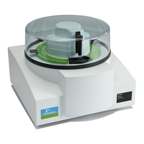
Page 56: Tga 4000 Thermogravimetric Analyzer
Also, since measurements can be performed in a well-defined atmosphere, the behavior of a sample in atmospheres other than air can be studied easily. The TGA 4000 can be used for component analysis (weight %), evaluation of stabilizers, loss on drying, proximate analysis, lubricating oil analysis, and oxidation studies. -
Page 57: Features Of The Tga 4000
The TGA 4000 has a top- loading microbalance. The sample pan is placed onto the sample holder which connects to the microbalance via a very thin rod. -
Page 58: Heating
58 . TGA 4000 Installation and Hardware Guide Heating The basic temperature range of the TGA 4000 is from ambient to 995 °C. Since the system is liquid-cooled, it is possible, in principle, to begin a run at subambient temperatures. -
Page 59: Sample Handling
TGA 4000 Hardware . 59 Sample Handling The TGA 4000 measures the change in weight of a sample as a function of temperature or time. The materials and techniques used to obtain data with a TGA 4000 are discussed below. -
Page 60: Loading The Sample Into The Tga 4000
60 . TGA 4000 Installation and Hardware Guide The gas atmosphere should be pure (99.9% minimum), especially if you use nitrogen. There should be no trace of oxygen as this could lead to unwanted reactions. The gas must be dry. -
Page 61: Calibration
Some of the conditions that could change either the temperature or the weight calibration of the TGA 4000 and require recalibration are as follows: •... -
Page 62: Maintenance
Cleaning the Cover The reaction byproducts from the samples run inside the STA 6000, TGA 4000 and Pyris 6 TGA furnace and condense on cold spots of the instrument: the bottom side of the cover and the top inner part of the cooling jacket. -
Page 63: Changing The Sample Thermocouple
Changing the Sample Thermocouple The sample thermocouple has a limited lifetime because of the range of temperatures and the high maximum temperature it withstands. Therefore, the TGA 4000 and Pyris 6 TGA are designed so that a user can change the sample thermocouple. - Page 64 64 . TGA 4000 Installation and Hardware Guide 8. While holding the plug, gently lift the thermocouple up and out of the furnace. Be careful not to bend the thermocouple. Note how the thermocouple is positioned in the furnace wall.
-
Page 65: Tga 4000 Part Numbers
If you are located within the U.S., call toll free at 1-800-762-4000, 8:30 a.m. – 7 p.m. EST. Your order will be shipped promptly, usually within 24 hours. • If you are located outside the U.S., call your local PerkinElmer sales office. or go on-line to www.perkinelmer.com Below is a list of the part numbers that are in the Spares kit (P/N N520-0110). -
Page 66: Miscellaneous Part Numbers
66 . TGA 4000 Installation and Hardware Guide Also included with the TGA 4000 are: Tygon tubing (P/N 0250-6519) for connection of liquid coolant • • Teflon tubing (P/N 0250-8059) for purge gas connection • 5/16-in. pipe for Swagelok Cooling Liquid In and Out connectors •... -
Page 67: As 6000 Autosampler
AS 6000 Autosampler... -
Page 68: As 6000 Autosampler
For the DSC 4000 and DSC 6000, you can use the existing robotic sample pans sealed with the Universal crimper press. All other standard sample pans (sealed and vented) can also be used. For the TGA 4000 and the STA 6000 the standard crucible (ceramic pan) is used. - Page 69 AS 6000 Autosampler . 69 The trays can be removed independently so that you can load one with fresh samples while the autosampler runs samples in the other. You could also add samples to the tray “in use” to replace samples that are completed by pausing the play list. The Pyris Player feature allows for creation of sequences or play lists to operate the autosampler and instrument.
-
Page 70: Safety Precautions For The As 6000
The safety precautions to be followed when using the AS 6000 autosampler are the same as those for the parent instrument: STA 6000, DSC 4000, DSC 6000, or the TGA 4000. In addition, the following two precautions should be kept in mind: To rem ove the furnace lid(s) of the parent instrum ent, alw ays use tw eezers. -
Page 71: How The As 6000 Autosampler Works
The fingers are closed. The furnace lid (for the TGA 4000) or lids (for the DSC 4000 or DSC 6000) are on the lid holders in the furnace access hole. The gripper device is instructed via a command in the Pyris software to begin a session. - Page 72 To remove the last sample from the furnace do a "Prepare Sample -Return Sample # #" as the last Play list step, where # # is the last sample loaded. A typical work cycle for the autosampler on a TGA 4000 or an STA 6000 and used with a play list is as follows: NOTE: Before the start of a play list, the gripper should be over the home position and there should be no sample pan in the furnace.
-
Page 73: Reduced Time Cycle
13. The system places the lower lid back into the furnace. 14. The upper lid is placed back on the lid holder. 15. The gripper goes to the home position. The procedure for the STA 6000/TGA 4000 is similar to the procedure above. -
Page 74: As 6000 Autosampler Gripper Alignment
74 . TGA 4000 Installation and Hardware Guide AS 6000 Autosampler Gripper Alignment The autosampler is aligned at the factory. However, if you install a reference pan into your DSC instrument or change the sample thermocouple of your TGA instrument, change the sensor, or if the gripper does not grasp the sample pans correctly, you should perform a gripper alignment procedure. -
Page 75: As 6000 Sample Handling
10, 25, 30, and 50 µL. Sample Loading Before loading the sample into the crucibles for the TGA 4000 or STA 4000, you will have to tare the crucibles, that is, have the system weigh them so the weight of the crucible is not included in the data. - Page 76 76 . TGA 4000 Installation and Hardware Guide When you click the OK button in the Advanced Tare Options dialog box, the Tare/Weigh System screen appears:...
- Page 77 AS 6000 Autosampler . 77 The Sample List will now display the tare weights of the crucibles: Once the empty crucibles are tared, remove each crucible and load the prepared sample into each one. Return the crucible to the correct position in the tray. Now the system can weigh all the samples before running the play list, or you can have each sample weighed at the beginning of its run.
-
Page 78: Running A Play List With The As 6000
There are many ways to use the play list with the autosampler. A quick way to create a play list for an STA 6000 or a TGA 4000 using the Sample Group feature is given below: – Load empty sample pans into the locations you want to use in the sample tray. - Page 79 AS 6000 Autosampler . 79 – Click OK and the Tare/Weigh System dialog box appears. The AS 6000 begins the procedure of taring the sample pans present on the sample trays. As it finds and tares each pan, it populates the Sample List and includes the tare weight for the sample pan in the Sample line.
- Page 80 80 . TGA 4000 Installation and Hardware Guide – Remove the sample trays from the autosampler, or leave them in place, to load the crucibles. If you removed the trays, carefully return them to the autosampler and make sure that the two knobs on the bottom of each tray engage the holes in the autosampler plate.
- Page 81 AS 6000 Autosampler . 81 8. Save the play list by selecting Save Player from the File menu. 9. Start playback of the play list by clicking the Start at Top button or the Start at Current Item button on the Player toolbar. These are the first two buttons on the toolbar: NOTE: If you select the Start at Current Item button, the focused item must be a main-level item, that is, Prepare Sample, Data Analysis, or Sample Group.
-
Page 82: Troubleshooting
82 . TGA 4000 Installation and Hardware Guide Troubleshooting When the AS 6000 autosampler malfunctions, in most cases it will generate an error message which is sent to the computer and is displayed in the Pyris software. The troubleshooting list below should be used if the AS 6000 malfunctions. - Page 83 AS 6000 Autosampler . 83 Error message ID Error Possible Corrective Cause Action ERR_GRP_NO_SAMPLE Gripper contains no There was no Place a sample sample when entering sample pan at on position 0 of furnace. Light switch in the reserved the sample tray state position on the sample tray...
- Page 84 84 . TGA 4000 Installation and Hardware Guide Error message ID Error Possible Corrective Cause Action ERR_FURN_NOT_EMPTY Furnace still contains a Failure picking Check if gripper sample while trying to sample out of fingers are bent. load a new one. This...
-
Page 85: Error Messages From The Tga 4000
AS 6000 Autosampler . 85 Error Messages from the TGA 4000 Error message ID Error Possible Cause Corrective Action ERR_DUE_TO_AUTOSAMPLER AS 6000 entered Refer to AS 6000 Refer to AS 6000 fatal error state. error message troubleshooting This caused TGA... -
Page 86: As 6000 Autosampler Maintenance
Cleaning and Decontamination Before using any cleaning or decontamination methods except those specified by PerkinElmer, you should check with PerkinElmer that the proposed method will not damage the equipment. There are no user-serviceable parts inside the autosam pler. -
Page 87: Replace The Sample Thermocouple In A Tga 4000, Pyris 6 Tga Or Sta 6000 With As 6000 Autosampler
AS 6000 Autosampler . 87 Replace the Sample Thermocouple in a TGA 4000, Pyris 6 TGA or STA 6000 with AS 6000 Autosampler 1. Switch off the instrument. 2. Remove both sample trays. 3. Remove the four screws that attach the autosampler to the base plate. - Page 88 88 . TGA 4000 Installation and Hardware Guide 10. Remove the thermocouple by disconnecting the thermocouple connector and gently pulling the thermocouple out of the furnace. 11. Install the new thermocouple and replace the sample holder, alumina furnace cover disk, and the alsiflex strip.
Need help?
Do you have a question about the TGA 4000 and is the answer not in the manual?
Questions and answers