molex AT-200 Operating And Maintenance Instructions Manual
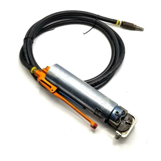
Air-powered crimping tool with optional bench adapter and foot switch
Hide thumbs
Also See for AT-200:
- Operating and maintenance instructions manual (20 pages) ,
- Operating and maintenance instructions manual (18 pages) ,
- Manual (8 pages)
Table of Contents
Advertisement
Quick Links
Advertisement
Table of Contents

Subscribe to Our Youtube Channel
Related Manuals for molex AT-200


Summary of Contents for molex AT-200
- Page 1 AT-200 Air-Powered Crimp Tool AT-200 AIR-POWERED CRIMPING TOOL Operating and Maintenance Instructions with Optional Bench Adapter and Foot Switch Description § Operation § Maintenance § UNCONTROLLED COPY Order No. 19279-0001 Release Date: 07-01-02 Page 1 of 19 Revision: B Revision Date: 06-18-03...
- Page 2 INSTALL OR SERVICE THIS MACHINE WHILE CONNECTED TO THE COMPRESSED AIR SOURCE. CAUTION THE MOLEX AT-200 AIR POWERED CRIMPING TOOL IS DESIGNED TO BE USED WITH AIR POWERED CRIMP TOOLS HEADS AND TOOLING SUPPLIED BY MOLEX. USE OF TOOL HEADS OR TOOLING FROM ANY OTHER SOURCE MAY RESULT IN DAMAGE OR INJURY.
- Page 3 AT-200 Air-Powered Crimp Tool Table of Contents General Description Changing Crimping Heads Parts List, Assembly Drawings and Maintenance Appendix Options UNCONTROLLED COPY Order No. 19279-0001 Release Date: 07-01-02 Page 3 of 19 Revision: B Revision Date: 06-18-03...
-
Page 4: General Description
2. Connect air hose to tool and to air supply 85 to 95 PSI. Do not exceed 100 PSI. May cause injury or damage to the tool. Air supply must be equipped with a 1/4NPT air filter /regulator which is not supplied by Molex (See Figure 1). (Available from any Industrial supply co.) - Page 5 AT-200 Air-Powered Crimp Tool 3. Lock trigger by engaging red aluminum safety. Pull the safety outward from end of trigger and rotate until next detent position engages (See Figure 3). TRIGGER TRIGGER SAFETY SAFETY (LOCKED) (UNLOCKED) PUSH IN PULL OUT Figure 3 Note: Always use the safety or disconnect air supply when changing crimping Heads.
- Page 6 AT-200 Air-Powered Crimp Tool Section 2 Changing Crimp Tool Heads Insulation Support Crimp Adjustment (Older style fixed jaw air powered crimp tools heads) Insulation Support Crimp Adjustment (Newer style insertion air powered crimp tools heads) Terminal Crimping UNCONTROLLED COPY Order No. 19279-0001...
- Page 7 AT-200 Air-Powered Crimp Tool 2.1 Changing Crimp Tool Heads 1. Engage trigger safety or disconnect air supply. TRIGGER SAFETY 2. Remove the two 1 /4” – 20 (LOCKED) slotted screws on both sides of power unit. Pull crimp tool head jaw assembly out of tool (See Figure 4).
- Page 8 AT-200 Air-Powered Crimp Tool If cam is not lined up, use the following procedure. a) Disconnect air supply with cam in the retracted position, which is trigger up. b) Grasp center section of cam with long nose pliers and rotate cam clockwise (CW) until center line of wedge lines up with 1 /4”...
- Page 9 4. If crimp configuration is too loose, change adjustment setting by removing from the AT-200 and setting adjustment screw to the S position. Re-insert the air powered crimp tool head into the AT- 200 and crimp, and inspect insulation support sleeve.
- Page 10 AT-200 Air-Powered Crimp Tool Section 3 Parts Lists and Assembly Drawings Maintenence UNCONTROLLED COPY Order No. 19279-0001 Release Date: 07-01-02 Page 10 of 19 Revision: B Revision Date: 06-18-03...
- Page 11 Order No. Engineering No. Description Notes 19279-0001 19279-0001 Air Power Crimp Tool Assembly (Fig. 9) 19279-0080 19279-0080 Cam For AT-200 Air Tool 19279-0135 19279-0135 AT-200 Air Powered Crimping Tool (Fig. 10) 19279-0140 19279-0140 Air Hose 1/8 NPT Male FTG 19279-0161 19279-0161 Screw Silver Slotted 1/4 –...
- Page 12 Description Notes 19279-0135 19279-0135 AT-200 Air Powered Crimping Tool (Fig 10) 1/4 ID by 3/8 OD by 1/16 CROSS SECTION BUNA O-RING 5/32 ID by 9/32 OD by 1/16 CROSS SECTION BUNA O-RING 3/8 ID by 1/2 OD by 1/16 CROSS SECTION BUNA O-RING 1/2 ID by 11/16 OD by 3/32 CROSS SECTION BUNA O-RING 1.
- Page 13 AT-200 Air-Powered Crimp Tool 3.1 Parts List and Assembly Drawings Figure 10 UNCONTROLLED COPY Order No. 19279-0001 Release Date: 07-01-02 Page 13 of 19 Revision: B Revision Date: 06-18-03...
- Page 14 AT-200 Air-Powered Crimp Tool 3.1 Parts List and Assembly Drawings Item Order No. Engineering No. Description Notes 19078-0307 19078-0307 Optional Bench Adapter REF (Fig 11) Dual Air Hose (1/8 ID x 8’) Air Foot Switch (3B – 30A2 – S) Fitting, 1/8 NPT –...
-
Page 15: Maintenance
AT-200 Air-Powered Crimp Tool 3.3 Maintenance Crimping nest should be kept free of all foreign particles. Crimp tool head assemblies should be lubricated monthly by placing a few drops of light machine oil on the pivot pins and cam follower rollers. - Page 16 AT-200 Air-Powered Crimp Tool Appendix A Options Accessories 64001-4000 Full Cycle/Pressure Electrical Control Box Instruction Sheet UNCONTROLLED COPY Order No. 19279-0001 Release Date: 07-01-02 Page 16 of 19 Revision: B Revision Date: 06-18-03...
-
Page 17: Operation
AT-200 Air-Powered Crimp Tool Accessory 64001-4000 Full Cycle/Pressure Electrical Control Box Instruction Sheet DESCRIPTION § The 64001-400 Full Cycle Electrical Control Box is an option for use on Air Power Crimp Tool (AT200) part no.19279-0001 equipped with Bench Adapter part no.19078-0307. -
Page 18: Parts List
AT-200 Air-Powered Crimp Tool Parts List Item Order No. Description 64001-4000 Electrical Controls (Timed Cycle) Fig 3 62500-1265 Power Supply 63800-8394 Footswitch Assembly 69018-6237 Power Cord 1/4“. OD Tubing 1/8 NPT by 1/4 Tube Fitting 19078-0307 Bench Adapter 19279-0001 Air Power Crimp Tool... -
Page 19: Corporate Headquarters
Tel: 49-89-413092-0 Fax: 49-89-401527 Corporate Headquarters 2222 Wellington Court Lisle, IL, 60532, U.S.A Tel: 1-800-78MOLEX Fax: 630-969-1352 Visit our Web site at http://www.molex.com UNCONTROLLED COPY Order No. 19279-0001 Release Date: 07-01-02 Page 19 of 19 Revision: B Revision Date: 06-18-03...
Need help?
Do you have a question about the AT-200 and is the answer not in the manual?
Questions and answers