
Related Manuals for Screen Innovations 5 Motorized


Summary of Contents for Screen Innovations 5 Motorized
- Page 1 5 Motorized Owner’s Manual Screen Innovations Control - RTS 9715-B Burnet Rd, Suite 400 Austin, TX 78758 512.832.6939 www.screeninnovations.com INSTALLERS: PLEASE LEAVE THIS MANUAL WITH THE OWNER.
-
Page 2: Table Of Contents
Mounting Flush L - Brackets..............10 your Screen Innovations' dealer. If it is necessary for the dealer to return the screen or part to Screen Hang Case And Raise Up Flush L - Brackets . -
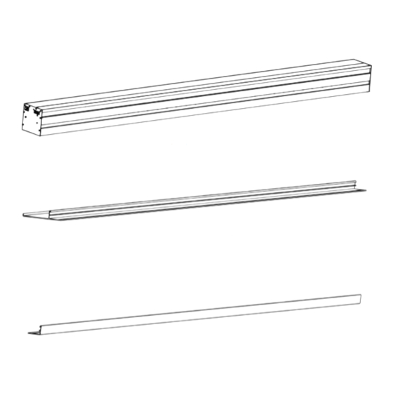
Page 3: Parts In The Box
PARTS IN THE BOX - FLUSH - 110v AC L-Bracket / Suspended Ceiling Bracket Screen Suspended Ceiling Bracket Kit Front Closure Rear Closure L - Brackets * NOTE: Screws are provided to mount to wooden structural supports only. If other substrate is present then installer must provide appropriate fasteners. - Page 4 PARTS IN THE BOX - FLUSH - 24v DC PARTS IN THE BOX - EXTERNAL - 110v AC L-Bracket / Suspended Ceiling Bracket Screen Screen Suspended Ceiling Bracket Kit Front Closure Front Closure Rear Closure L - Brackets * NOTE: Screws are provided to mount to wooden structural supports only. If other substrate is Fascia present then installer must provide appropriate fasteners.
-
Page 5: Pre-Wiring
PARTS IN THE BOX - EXTERNAL - 24v DC PRE-WIRING - 110v - RTS 1. Make sure an appropriate junction box or power receptacle is located within 5ft of the installation location. 2. Wire in the pigtail power cable at the junction box per electrical code standards. Antenna is part of Pigtail Cable. -
Page 6: Mounting Case Type
PRE-WIRING - 24v - RTS MOUNTING CASING - TYPE 1. Run minimum 2 conductor wire to the left side of screen cassette installation location Installation requires two or more people. Bend knees when lifting. To be sure you have the correct wire, order directly from SI (Part # - Non-Plenum - 800269/ 9020126 and Plenum rated - 9020127). - Page 7 INSTALLATION - FLUSH INSTALLATION - FLUSH Measure Case & Cut Out Pocket Add End Flange & Remove Weight Bar Lock FLUSH L FLUSH SUSPENDED FLUSH L FLUSH SUSPENDED Measure the case length and record the measurement. If pre constructing the pocket then Line up the holes on the removable flanges with the holes in the end plates.
-
Page 8: Mounting Flush L Brackets
INSTALLATION - FLUSH INSTALLATION - FLUSH Mounting Flush L Brackets Hang Case on L-Brackets and Raise Up FLUSH L FLUSH L Mount the L brackets either to a vertical or horizontal structural support as shown. Make sure brackets are all along the same level line and plumb. Installation requires two or more people. -
Page 9: Mounting Flush Suspended Brackets
INSTALLATION - FLUSH INSTALLATION - FLUSH Mounting Flush Suspended Brackets Hang Case on Suspended Brackets and Raise Up FLUSH SUSPENDED FLUSH SUSPENDED Install minimum 3/8’’ threaded rod to structural members in the ceiling per the drawing Raise the case up and guide the threaded rods through the holes in the suspended ceiling below. - Page 10 INSTALLATION - EXTERNAL INSTALLATION - EXTERNAL Measure case & Mount L Brackets Remove Weight Bar Lock, Hang Case and Raise Up EXTERNAL EXTERNAL Measure the case length and record the measurement. Remove the tagged Weight Bar Locks. Mount the L brackets either to a vertical or horizontal structural support as shown. Make sure brackets are all along the same level line and plumb.
-
Page 11: Trim Installation Flush
TRIM INSTALLATION - FLUSH TRIM INSTALLATION - FLUSH Flush Trim Install Flush Trim Locking FLUSH L FLUSH SUSPENDED FLUSH L FLUSH SUSPENDED Hook the larger front closure into the case opposite the weight bar and then rotate Insert the bumpers into the holes in the endplates. Press the pin in the bumper until you down to secure. -
Page 12: Trim Installation External
TRIM INSTALLATION - EXTERNAL TRIM INSTALLATION - EXTERNAL Fascia Install & Fascia Lock Trim Install EXTERNAL EXTERNAL Hook the front trim into the case opposite the weight bar and then rotate down Use the 9/64’’ hex key to loosen the two screws securing the fascia lock. Then slide the to secure. -
Page 13: Rts - Running
24V RTS - PROGRAMMING The RF remote, supplied with the screen, controls the deployment and retraction from up to 30 Setting the Drop - 5 Motorized is factory preset to have 12’’ to 48” of drop, the distance between feet away. Enjoy! the top of the viewing area and the cassette. -
Page 14: Pairing Another Rf Remote Using Original Remote
If another remote was purchased, it will not come paired to your screen motor. To pair it, first take the working remote supplied with the 5 Motorized and press the Program button on the back of the remote until the screen jogs once. Holding the new remote, briefly press* the Program button on the back. -
Page 15: Adjusting The Screen Tension
TROUBLESHOOTING Problems related to electrical or motor function may require a qualified service person or electrician. Should you have a problem that is not addressed here, call: Screen Innovations (512-832-6939.) http://www.screeninnovations.com/category/support/ Press in the button and turn knob counter clockwise untill the string is loose. -
Page 16: Motor Accessories
TROUBLESHOOTING MOTOR ACCESSORIES Purchased Seperately Problem Description Probably Cause Action to Take Indentations appear Debris or particles Check back of screen as well as front of screen for on screen surface. adhering to screen due dust or debris. Wipe the back of the screen with a to static cling.
Need help?
Do you have a question about the 5 Motorized and is the answer not in the manual?
Questions and answers