
Related Manuals for Rice Lake Revolution SURVIVOR 420HE


Summary of Contents for Rice Lake Revolution SURVIVOR 420HE
-
Page 1: Installation Manual
SURVIVOR 420HE Hostile Environment Digital Weight Indicator Version 1.15 Installation Manual 87972 Rev B... - Page 2 All information contained within this publication is, to the best of our knowledge, complete and accurate at the time of publication. Rice Lake Weighing Systems reserves the right to make changes to the technology, features, specifications and design of the equipment without notice.
-
Page 3: Table Of Contents
Course descriptions and dates can be viewed at www.ricelake.com/training or obtained by calling 715-234-9171 and asking for the training department. © Rice Lake Weighing Systems. All rights reserved. Printed in the United States of America. Specifications subject to change without notice. - Page 4 1.1 Front Panel Calibration............. 27 1.2 EDP Command Calibration .
-
Page 5: About This Manual
Revolution III configuration utility. See Section 1.1 on page 13 for information about configuration methods. Authorized distributors and their employees can view or download this manual from the Rice Lake Weighing Systems distributor site at www.rlws.com The Operator Card included with this manual provides basic operating instructions for users of the 420 Plus. -
Page 6: Introduction
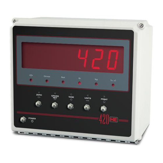
Introduction The 420 Plus is a single-channel digital weight indicator housed in a NEMA 4X/IP66-rated FRP enclosure. The indicator front panel consists of a large (1.8 in, 44.5 mm), six-digit, seven-segment LED display and six-button keypad. Features include: • Drives up to eight 350or sixteen 700 load cells •... -
Page 7: Front Panel Keypad
Front Panel Keypad Figure 1-1 shows the 420 Plus LED annunciators, keypad, and normal mode key functions.The symbols shown above the keys (representing up, down, enter, left, right) describe the key functions assigned in setup mode. In setup mode, the keys are used to navigate through menus, select digits within numeric values, and increment/ decrement values. -
Page 8: Indicator Operations
Table 1-1 shows which annunciators are used for all combinations of configured primary and secondary units. For example: • If the primary unit is pounds (lb) and the secondary unit is kilograms (kg), the LED is lit for primary units, for secondary units. -
Page 9: Display Or Change Setpoint Value
Sub Menu – Press and hold UNITS key for three seconds SETPNT T/DATE TIME SETPT1 SETPT2 DATE Same as SETPT 1 010104 0000 NOTE: The indicator will begin incrementing time at power up. ENABLE BNDVAL HYSTER V ALUE number number number NOTE: Only Available when ACCESS = ON See Figure 3-11 on page 23 and Table 3-7... -
Page 10: Installation
Plus to ensure all components are included and undamaged. The shipping carton should contain the indicator, this manual, and a parts kit. If any parts were damaged in shipment, notify Rice Lake Weighing Systems and the shipper immediately. The parts kit (PN 87973) contains the items listed Figure 1-1. -
Page 11: Cable Grounding
1.3.1 Cable Grounding • Route stripped cables through cord grips and clamps. Ensure shields contact grounding clamps Except for the power cord, all cables routed through the as shown in Figure 1-2. Tighten grounding clamp cord grips should be grounded against the CPU nuts. -
Page 12: Load Cells
1.3.2 Load Cells Port Connector Label Using one of the 6-position connectors, provided in the parts kit, wire the load cell cable from the load cell or Serial Port junction box to connector J1 on the CPU board (See Figure 1-3 7). If using six-wire load cell cable (with sense wires), remove jumpers JP1 and JP2 before 20mA+ reinstalling connector J1 (see Figure 1-3). -
Page 13: Analog Output Module Installation
Board Removal If you must remove the 420 Plus CPU board, use the Signal following procedure: + Current Out 1. Disconnect power to the indicator. – Current Out 2. Open indicator using draw latches. + Voltage Out 3. Disconnect power supply cable from connector –... -
Page 14: Replacement Parts
Replacement Parts Table 1-5 lists replacement parts for the 420 Plus, including all parts referenced in Figures 1-5 and 1-6. Number Description (Quantity) Figure 14842 Screws, 32NC x 5/16 (6) See Figure 1-5 11 87962 Enclosure (1) Lock nut, hex 32NC 58248 Power supply bracket (1) 82856... - Page 15 To Power Supply From Power Supply From Power Supply 420 Plus Figure 1-5. Assembly Drawing...
- Page 16 Grounding Detail Ground Wire From Power Cord (17) Ground Screw In Bottom Panel (12) 2X Cable Tie Wires Using 2 Holes Provided In Bracket Wire Tie Squares 420 Plus Figure 1-6. Assembly Drawing 420HE Installation Manual...
-
Page 17: Configuration
Configuration To configure the 420 Plus indicator, the indicator must To use Revolution, do the following: be placed in setup mode. The setup switch is accessed Revolution 1. Install module by opening the enclosure and pressing the setup switch. IBM-compatible personal computer running ®... -
Page 18: Front Panel Configuration
1.1.3 Front Panel Configuration The 420 Plus indicator can be configured using a series of menus accessed through the indicator front panel when the indicator is in setup mode. Table 1-1 summarizes the functions of each of the main menus. Menu Menu Function CONFIG... -
Page 19: Menu Structures And Parameter Descriptions
To select a parameter, press to scroll left or right until the desired menu group appears on the display, then press to move down to the submenu or parameter you want. When moving through the menu parameters, the default or previously selected value appears first on the display. - Page 20 CONFIG Menu Parameter Choices Description Level 2 submenus GRADS 10000 Graduations. Specifies the number of full scale graduations. The value entered must be in number the range 1–100 000 and should be consistent with legal requirements and environmental limits on system resolution. To calculate GRADS, use the formula, GRADS = Capacity / Display Divisions.
-
Page 21: Format Menu
CONFIG Menu Parameter Choices Description DFTHRH NONE Digital filter cutout threshold. Specifies the filter threshold, in display divisions. When a specified number of consecutive scale readings (DFSENS parameter) fall outside of this threshold, digital filtering is suspended. If NONE is selected, the filter is always enabled. 10DD 20DD 50DD... - Page 22 FORMAT Menu Parameter Choices Description DSPRAT 250MS Display rate. Sets the update rate for displayed values. Values are in milliseconds (MS) or 500MS seconds (SEC). 750MS 1SEC 1.5SEC 2SEC 2.5SEC 3SEC 4SEC 6SEC 8SEC Level 3 submenus Primary Units (PRIMAR Parameter) DECPNT 888888 Decimal point location.
-
Page 23: Calibration Menu
1.2.3 Calibration Menu See Section 1.0 on page 27 for Calibration procedures. CONFIG XXXXXXX FORMAT CALIBR SERIAL PROGRM XXXXXXX PFORMT SETPNT XXXXXXX DIGI N XXXXXXX ALGOUT VERS WZERO WV AL WSPAN REZERO Figure 1-7. Calibration Menu CALIBR Menu Parameter Choices Description Level 2 submenus WZERO... - Page 24 SERIAL Menu Parameter Choices Description Level 2 submenus BAUD Specifies settings for baud rate, data bits, termination characters, end-of-line delay and echo BITS used by the EDP port. TERMIN EOLDLY ECHO PRINT BAUD Specifies settings for baud rate, data bits, termination characters, end-of-line delay and echo BITS used by the printer port.
-
Page 25: Program Menu
1.2.5 Program Menu CONFIG XXXXXXX FORMAT CALIBR SERIAL PROGRM XXXXXXX PFORMT SETPNT DIGIN ALGOUT VERS PWRUPM REGULA CONSNU CONSTU DA TE TIME 000000 000000 NTEP DA TFMT DA TSEP TIMFMT TIMSEP DELAY OIML number number MMDDYY SLASH 24HOUR COLON CANADA DDMMYY DASH 12HOUR... -
Page 26: Print Format Menu
PROGRM Menu Parameter Choices Description DATFMT MMDDYY Specifies the format used to display or print the date. DDMMYY YYMMDD DATSEP SLASH Specifies the date separator character. DASH SEMI TIMFMT 24HOUR Specifies the format used to display or print the time. 12HOUR TIMSEP COLAN... -
Page 27: Setpoint Menu
1.2.7 Setpoint Menu CONFIG FORMAT CALIBR SERIAL PROGRM PFORMT XXXXXXX XXXXXXX SETPNT XXXXXXX DIG IN XXXXXXX ALGOUT VERS XXXXXXX SETPT1 SETPT2 Same as SETPT1 ENABLE KIND V ALUE TRIP BNDVAL HYSTER ACCESS GROSS number HIGHER number number LOWER If TRIP = HIGHER/ INBAND LOWER OUTBAND... -
Page 28: Digital Input Menu
1.2.8 Digital Input Menu CONFIG FORMAT CALIBR SERIAL PROGRM PFORMT SETPNT DIGI N ALGOUT VERS XXXXXXX XXXXXXX XXXXXXX XXXXXXX DIGIN1 DIGIN2 ZERO ZERO T ARE T ARE NT/GRS NT/GRS UNITS UNITS DSPTAR DSPTAR PRINT PRINT CLRCN CLRCN KBDLOC KBDLOC HOLD HOLD NEWID NEWID... -
Page 29: Analog Output Menu
1.2.9 Analog Output Menu The ALGOUT menu is used only if the analog output option is installed. If the analog output option is installed, OF F S ET ERRACT MI N T W ZERO T W SPA configure all other indicator functions and calibrate the indicator (see Section 1.0) before configuring the analog output. -
Page 30: Version Menu
1.2.10 Version Menu The VERS menu is used to check the software version and reg version installed in the indicator. You can also check the indicator model. CONFIG FORMAT XXXXXXX CALIBR SERIAL PROGRM PFORMT XXXXXXX SETPNT XXXXXXX DIGI N ALGOUT VERS SOFTWR MODEL... -
Page 31: Calibration
Calibration The 420 Plus can be calibrated using the front panel, EDP commands, or the Revolution ® configuration utility. Each method consists of the following steps: • Zero calibration • Entering the test weight value • Span calibration • Optional rezero calibration for test weights using hooks or chains. The following sections describe the calibration procedure for each of the calibration methods. -
Page 32: Edp Command Calibration
EDP Command Calibration 4. The Zero Calibration dialog box prompts you to remove all weight from the scale. Clear the To calibrate the indicator using EDP commands, the scale and click to begin zero calibration. indicator EDP port must be connected to a terminal or If your test weights require hooks or personal computer. -
Page 33: Edp Commands
EDP Commands The 420 Plus indicator can be controlled by a personal computer or remote keyboard connected to the Command Function indicator EDP port. Control is provided by a set of EDP commands that can simulate front panel key press KZERO In weighing mode, press the ZERO key functions, display and change setup parameters, and... -
Page 34: Reporting Commands
1.1.2 Reporting Commands 1.1.4 Parameter Setting Commands Reporting commands (see Table 1-2) send specific Parameter setting commands allow you to display or information to the EDP port. These commands can be change the current value for a particular configuration used in both setup mode and normal mode. parameter (Tables 1-3 through 1-11). - Page 35 Command Description Values PRI.DECPNT Primary units decimal position 8.88888, 88.8888, 888.888, 8888.88, 88888.8, 888888, 888880 PRI.DSPDIV Primary units display divisions 1D, 2D, 5D PRI.UNITS Primary units LB, KG, OZ, TN, T, G, NONE SEC.DECPNT Secondary units decimal position 8.88888, 88.8888, 888.888, 8888.88, 88888.8, 888888, 888880 SEC.DSPDIV Secondary units display divisions 1D, 2D, 5D...
- Page 36 Command Description Values PWRUPMD Power up mode GO, DELAY REGULAT Regulatory compliance NTEP, OIML, CANADA, NONE CONSNUM Consecutive number 0–999 999 CONSTUP Consecutive number start-up value 0–999 999 DATEFMT Date format MMDDYY, DDMMYY, YYMMDD, YYDDMM DATESEP Date seperator SLASH, DASH, SEMI TIMEFMT Time format 12HOUR, 24HOUR...
-
Page 37: Normal Mode Commands
Command Description Values SOURCE Analog output source GROSS, NET OFFSET Zero offset 0%, 20% ERRACT Error action FULLSC, HOLD, ZEROSC Minimum value tracked 0–999 999 MINNEG Minimum negative OFF, ON Maximum value tracked 0–999 999 MAXNEG Maximum negative OFF, ON TWZERO Zero calibration 0–16 383... -
Page 38: Saving And Transferring Data
Saving and Transferring Data 1.2.2 Downloading Configuration Data from PC to Indicator Connecting a personal computer to the 420 Plus EDP Configuration data saved on a PC or floppy disk can be port allows you to save indicator configuration data to downloaded from the PC to an indica tor. -
Page 39: Print Formatting
Print Formatting The 420 Plus provides two print formats, GFMT and Command Description NFMT that determine the format of the printed output when the key is pressed or when a KPRINT EDP * If nn is not specified, 1 is assumed. Value must be in the PRINT range 1–99. -
Page 40: Using The Edp Port
A ticket printed using this format might look like the 1.2.1 Using the EDP Port With a personal computer, terminal, or remote following: keyboard attached to the 420 Plus EDP port, you can FINE TRANSFER CO use the EDP command set to customize the print 32400 WEST HIGHWAY ROAD format strings. -
Page 41: Using Revolution
® 1.2.3 Using Revolution The Revolution configuration utility provides a print formatting grid with a tool bar. The grid allows you to construct the print format without the formatting commands (<NL> and <SP>) required by the front panel or EDP command methods. -
Page 42: Appendix
Error Message Description Solution E A/D A/D physical error Call Rice Lake Weighing Systems (RLWS) Service. EEEROM EEPROM physical error EVIREE Virgin EEPROM Use TEST menu to perform DEFLT (restore defaults) procedure, then recalibrate load cells. -
Page 43: Using The Xe Edp Command
Status Messages 1.1.2 Using the XE EDP Command The XE EDP command can be used to remotely query Two EDP commands, P and ZZ, can be used to provide the 420 Plus for the error conditions shown on the front status about the indicator. -
Page 44: Continuous Output (Stream) Format
Continuous Output (Stream) Format Figure 1-1 shows the continuous output format sent to the 420 Plus EDP or printer port when the STREAM parameter (SERIAL menu) is set to either EDP or PRN. <STX> <POL> <wwwwwww> <UNIT> <G/N> <S> <TERM> ASCII 02 G = Gross <CR>... -
Page 45: Ascii Character Chart
ASCII Character Chart Use the decimal values for ASCII characters listed in Tables 1-4 and 1-5 when specifying print format strings on the 420 Plus PFORMT menu. The actual character printed depends on the character mapping used by the output device. - Page 46 ASCII ASCII ASCII ASCII Ç á ü í ß é ó â ú ä ñ à Ñ å ª µ ç º ê ¿ ë è ¬ ï î ...
-
Page 47: Front Panel Display Characters
Front Panel Display Characters Figure 1-2 shows the 7-segment LED character set used to display alphanumeric characters on the 420 Plus front panel. < & > 420 Plus Figure 1-2. Display Characters... -
Page 48: Conversion Factors For Secondary Units
Conversion Factors for Secondary Units Primary Unit x Multiplier Secondary Unit The 420 Plus has the capability to mathematically grains 0.064799 grams convert a weight into many different types of units and instantly display those results with a press of the 0.002286 ounces UNITS... -
Page 49: Digital Filtering
Digital Filtering The 420 Plus uses averaged digital filtering to reduce the effect of vibration on weight readings. Adjustable threshold and sensitivity functions allow quick settling by suspending filter averaging, allowing the weight reading to jump to the new value. Figure 1-3 shows the digital filter parameters on the CONFIG menu. DIGFL1 DIGFL2 DIGFL3... -
Page 50: Setting The Digital Filter Parameters
v i b r a t io n e f f e c t s o n t h e s c a le . ( L e a v e 1.7.3 Setting the Digital Filter Parameters DFTHRH set to NONE.) Reconfigure as Fine-tuning the digital filter parameters greatly necessary to find the lowest effective values improves indicator performance in heavy-vibration... -
Page 51: Test Mode
Test Mode To enter test mode, press and hold the setup switch until the front panel display shows the word TEST After about three seconds, the test mode display Note Test mode is intended for factory use only. automatically shifts to the first test menu function, A/ DTST. -
Page 52: 1.10 Regulatory Mode Functions
1.10 Regulatory Mode Functions Front Panel Key Function REGULAT Parameter Value Weight on Scale Tare in System TARE ZERO NTEP zero or negative no action ZERO CLEAR TARE positive TARE TARE CANADA zero or negative no action TARE CLEAR TARE positive TARE no action... -
Page 53: 1.12 Specifications
1.12 Specifications Serial Communications EDP Port Full duplex RS-232 Power Printer Port Full duplex RS-232 or active transmit Line Voltages 115 or 230 VAC only 20 mA current loop Frequency 50 or 60 Hz Both Ports 38400, 19200, 9600, 4800, 2400, 1200, 600, 300 bps;... -
Page 54: 420He Limited Warranty
420HE Limited Warranty Rice Lake Weighing Systems (RLWS) warrants that all RLWS equipment and systems properly installed by a Distributor or Original Equipment Manufacturer (OEM) will operate per written specifications as confirmed by the Distributor/OEM and accepted by RLWS. All systems and components are warranted against defects in materials and workmanship for two years. - Page 56 © Rice Lake Weighing Systems 07/19 PN 87972 Rev B...
Need help?
Do you have a question about the Revolution SURVIVOR 420HE and is the answer not in the manual?
Questions and answers