
Related Manuals for Infineon GPT12 Timer Concatenation 1


Summary of Contents for Infineon GPT12 Timer Concatenation 1
- Page 1 GPT12_Timer_Concatenation_1 Timer concatenation of GPT12 AURIX™ TC2xx Microcontroller Training V1.0.0 Please read the Important Notice and Warnings at the end of this document...
-
Page 2: Scope Of Work
LED. A 32-bit timer is formed by the concatenation of two 16-bit timers of the GPT12 module. When the 32-bit timer overflows, an interrupt is generated toggling an LED. 2019-10-17 Copyright © Infineon Technologies AG 2019. All rights reserved. - Page 3 An additional Capture/Reload register (CAPREL) supports also capture and reload operation. › The timer T5 in Counter Mode and the timer T6 in Timer Mode are used together in this example. 2019-10-17 Copyright © Infineon Technologies AG 2019. All rights reserved.
-
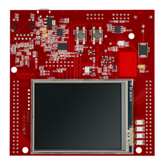
Page 4: Hardware Setup
Hardware setup This code example has been developed for the board KIT_AURIX_TC297_TFT_BC-Step. 2019-10-17 Copyright © Infineon Technologies AG 2019. All rights reserved. - Page 5 T6. IfxGpt12_T6_run() function starts timer T6 and implicitly timer T5, because the overflow of T6 is used as clock for T5. The functions above are provided by the iLLD header IfxGpt12.h. 2019-10-17 Copyright © Infineon Technologies AG 2019. All rights reserved.
- Page 6 IfxSrc_init() and IfxSrc_enable() provided by the iLLD header IfxSrc.h. › The method implementing the ISR needs to be assigned a priority and a CPU core responsible for its execution. This is done with the macro IFX_INTERRUPT(isr, vectabNum, priority). 2019-10-17 Copyright © Infineon Technologies AG 2019. All rights reserved.
- Page 7 Due to the timer concatenation, the ISR of timer T5 is triggered with the overflow of the 32-bit timer value. This ISR toggles an LED. › The 32-bit timer value is calculated in the ISR of T6 and is represented by timerValueHIGH (T5) and timerValueLOW (T6). 2019-10-17 Copyright © Infineon Technologies AG 2019. All rights reserved.
- Page 8 20 ns (1 / 50 MHz) – Overflow of 32-bit timer after ≈ 86 s (4294967295 * 20 ns) › Check in the debugger if parameter g_timerValue32Bit is incrementing 2019-10-17 Copyright © Infineon Technologies AG 2019. All rights reserved.
- Page 9 More code examples can be found on the GIT repository: › https://github.com/Infineon/AURIX_code_examples › For additional trainings, visit our webpage: › https://www.infineon.com/aurix-expert-training › For questions and support, use the AURIX™ Forum: › https://www.infineonforums.com/forums/13-Aurix-Forum 2019-10-17 Copyright © Infineon Technologies AG 2019. All rights reserved.
- Page 10 Infineon Technologies in in personal injury. customer’s applications. The data contained in this document is exclusively intended for technically trained staff.
Need help?
Do you have a question about the GPT12 Timer Concatenation 1 and is the answer not in the manual?
Questions and answers