
Related Manuals for Infineon CCU6 PWM Capture 1


Summary of Contents for Infineon CCU6 PWM Capture 1
- Page 1 CCU6_PWM_Capture_1 CCU6 PWM signal capture AURIX™ TC2xx Microcontroller Training V1.0.0 Please read the Important Notice and Warnings at the end of this document...
-
Page 2: Scope Of Work
A simple PWM signal is generated by toggling a port pin. The resulting PWM frequency and duty cycle is measured by the Capture/Control Unit 6 (CCU6). 2020-01-17 Copyright © Infineon Technologies AG 2020. All rights reserved. - Page 3 In this example, the Input Capture Unit and the timer T12 of the CCU6 module are used to capture a PWM signal and calculate its frequency and duty cycle. 2020-01-17 Copyright © Infineon Technologies AG 2020. All rights reserved.
-
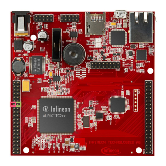
Page 4: Hardware Setup
This code example has been developed for the board KIT_AURIX_TC297_TFT_BC-Step. Connect the two pins P02.1 (PWM signal) and P02.0 (CC60 input) to each other. input pin A PWM signal of CC60 2020-01-17 Copyright © Infineon Technologies AG 2020. All rights reserved. - Page 5 (IfxCcu6_Icu) contains the configured capture frequency of the timer. For further usage, this parameter is stored in the global variable g_CCU6captureFrequency_Hz. All used functions and structures can be found in the iLLD header IfxCcu6_Icu.h. 2020-01-17 Copyright © Infineon Technologies AG 2020. All rights reserved.
- Page 6 T12 counter value with the period value) Note: An interrupt is needed to capture the PWM frequency, while the other counts the number of timer overflows (for more details, see slides 8-12). 2020-01-17 Copyright © Infineon Technologies AG 2020. All rights reserved.
- Page 7 IfxCcu6_Icu_initChannel()), the capture process is started by setting the run bit T12R through the function IfxCcu6_Icu_startCapture(). All functions and structures used for the configuration of the CCU6 channel can be found in the iLLD header IfxCcu6_Icu.h. 2020-01-17 Copyright © Infineon Technologies AG 2020. All rights reserved.
- Page 8 PWM duty cycle The method implementing each ISR needs to be assigned a priority and a CPU core responsible for its execution. This is done with the macro IFX_INTERRUPT(isr, vectabNum, priority). 2020-01-17 Copyright © Infineon Technologies AG 2020. All rights reserved.
- Page 9 (CCU6_ICU_Period_Match_Int_Handler()) which is used for counting: – the overflows between two rising edges for PWM frequency calculation – the overflows between the rising edge and the falling edge for PWM duty cycle calculation 2020-01-17 Copyright © Infineon Technologies AG 2020. All rights reserved.
- Page 10 T12 with the value of timer T12 one PWM period ago e.g. 1000 Interrupt on each rising edge: Period of timer T12 overflow T12 count (value is incremented with frequency of timer T12) Period of High level PWM signal PWM signal time 2020-01-17 Copyright © Infineon Technologies AG 2020. All rights reserved.
- Page 11 PWM period: – 781250 Hz / 390625 = 2 Hz › Duty cycle (increments during high level time / increments during total period) = 195312 / 390625 = 50% 2020-01-17 Copyright © Infineon Technologies AG 2020. All rights reserved.
- Page 12 (between 0 and 65534) PWM signal (2 Hz) Period of PWM signal 0.5 s 5 overflows of timer T12 during one PWM period Interrupt on previous rising edge Interrupt on current rising edge 2020-01-17 Copyright © Infineon Technologies AG 2020. All rights reserved.
- Page 13 (between 0 and 65534) PWM signal (2 Hz) Period of PWM signal 0.5 s 2 overflows of timer T12 during high level time Interrupt on previous rising edge Interrupt on current rising edge 2020-01-17 Copyright © Infineon Technologies AG 2020. All rights reserved.
- Page 14 IfxPort_setPinState(). The parameters and functions used for the port pin control and timing are provided by the two iLLD headers IfxPort.h and Bsp.h. 2020-01-17 Copyright © Infineon Technologies AG 2020. All rights reserved.
- Page 15 Check the parameter g_measuredPwmDutyCycle in the debugger (the debug session should be suspended previously). Its value should be similar to the parameter g_generatedPwmDutyCycle Change the parameter g_generatedDutyCycle and check if g_measuredDutyCycle changes accordingly 2020-01-17 Copyright © Infineon Technologies AG 2020. All rights reserved.
- Page 16 More code examples can be found on the GIT repository: › https://github.com/Infineon/AURIX_code_examples › For additional trainings, visit our webpage: › https://www.infineon.com/aurix-expert-training › For questions and support, use the AURIX™ Forum: › https://www.infineonforums.com/forums/13-Aurix-Forum 2020-01-17 Copyright © Infineon Technologies AG 2020. All rights reserved.
- Page 17 Infineon Technologies in in personal injury. customer’s applications. The data contained in this document is exclusively intended for technically trained staff.
Need help?
Do you have a question about the CCU6 PWM Capture 1 and is the answer not in the manual?
Questions and answers