
Related Manuals for Infineon GTM ATOM Interrupt 1


Summary of Contents for Infineon GTM ATOM Interrupt 1
- Page 1 GTM_ATOM_Interrupt_1 GTM ATOM interrupt AURIX™ TC2xx Microcontroller Training V1.0.0 Please read the Important Notice and Warnings at the end of this document...
-
Page 2: Scope Of Work
LED. The Generic Timer Module triggers an interrupt every 500 ms. The state of the port pin, where the LED is connected, is toggled inside the Interrupt Service Routine (ISR). 2019-10-17 Copyright © Infineon Technologies AG 2019. All rights reserved. - Page 3 The Clock Management Unit (CMU) is responsible for clock generation of the GTM. The Configurable Clock Generation Subunit (CFGU) provides eight clock sources for the GTM submodules TIM, TBU, MON and ATOM. 2019-10-17 Copyright © Infineon Technologies AG 2019. All rights reserved.
-
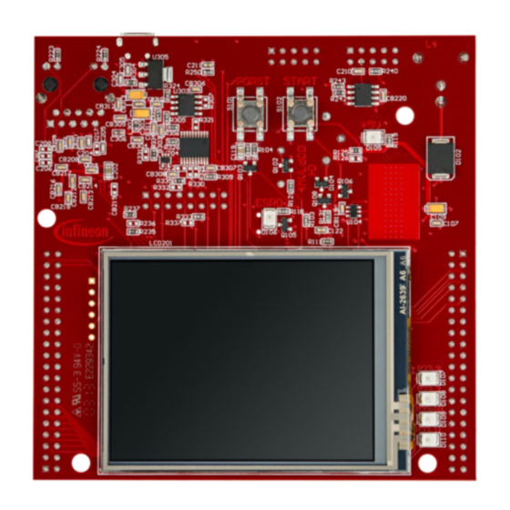
Page 4: Hardware Setup
Hardware setup This code example has been developed for the board KIT_AURIX_TC297_TFT_BC-Step. LED D107 (1) is used for this example. 2019-10-17 Copyright © Infineon Technologies AG 2019. All rights reserved. - Page 5 – Select CMU clock 0 – base.frequency – Set timer frequency to 2 Hz (interrupt every 500 ms) – base.isrPriority – Interrupt Service Routine priority – base.isrProvider – Interrupt Service Routine provider 2019-10-17 Copyright © Infineon Technologies AG 2019. All rights reserved.
- Page 6 The LED configuration is also done in the function initGtmAtom(): › Set the port pin mode to output and push-pull by calling the function IfxPort_setPinModeOutput(), provided by iLLD header IfxPort.h. 2019-10-17 Copyright © Infineon Technologies AG 2019. All rights reserved.
- Page 7 The ISR implemented in this example contains the following steps: › Clear the timer event with the function IfxGtm_Atom_Timer_acknowledgeTimerIrq() in the iLLD header IfxGtm_Atom_Timer.h › Change the LED state by calling the function IfxPort_togglePin() in the iLLD header IfxPort.h 2019-10-17 Copyright © Infineon Technologies AG 2019. All rights reserved.
- Page 8 Run and Test After code compilation and flashing the device, observe the LED D107 (1), which should be blinking. 2019-10-17 Copyright © Infineon Technologies AG 2019. All rights reserved.
- Page 9 More code examples can be found on the GIT repository: › https://github.com/Infineon/AURIX_code_examples › For additional trainings, visit our webpage: › https://www.infineon.com/aurix-expert-training › For questions and support, use the AURIX™ Forum: › https://www.infineonforums.com/forums/13-Aurix-Forum 2019-10-17 Copyright © Infineon Technologies AG 2019. All rights reserved.
- Page 10 Infineon Technologies in in personal injury. customer’s applications. The data contained in this document is exclusively intended for technically trained staff.
Need help?
Do you have a question about the GTM ATOM Interrupt 1 and is the answer not in the manual?
Questions and answers