
Related Manuals for Infineon CCU6 Interrupt 1


Summary of Contents for Infineon CCU6 Interrupt 1
- Page 1 CCU6_Interrupt_1 CCU6 interrupt generation AURIX™ TC2xx Microcontroller Training V1.0.0 Please read the Important Notice and Warnings at the end of this document...
- Page 2 1st LED: counter % 4 == 0 › 2nd LED: counter % 4 == 1 › 3rd LED: counter % 4 == 2 › 4th LED: counter % 4 == 3 2019-10-17 Copyright © Infineon Technologies AG 2019. All rights reserved.
- Page 3 In this example, Timer T12 Block is used. › Among other features, the CCU6 has the capability to generate interrupts when its count reaches a predefined period value (16-bit). 2019-10-17 Copyright © Infineon Technologies AG 2019. All rights reserved.
-
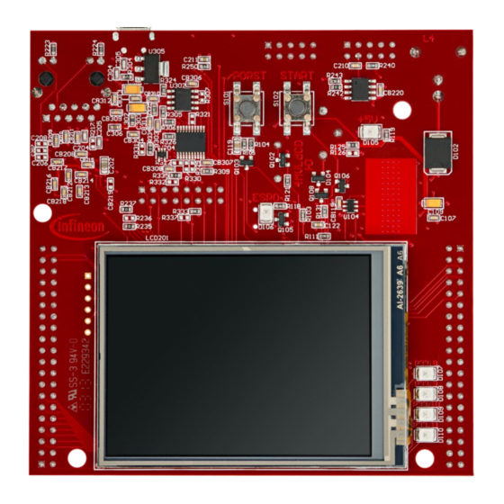
Page 4: Hardware Setup
Hardware setup This code example has been developed for the board KIT_AURIX_TC297_TFT_BC-Step. 2019-10-17 Copyright © Infineon Technologies AG 2019. All rights reserved. - Page 5 In the setup phase, the port pins connected to the LEDs are configured as push-pull output mode using the function IfxPort_setPinMode(). During program execution, the LEDs are switched on and off using the function IfxPort_setPinState(). 2019-10-17 Copyright © Infineon Technologies AG 2019. All rights reserved.
- Page 6 The function IfxCcu6_Timer_initModuleConfig() fills the configuration structure with default values and IfxCcu6_Timer_initModule() function initializes the timer module with the user configuration. Both functions can be found in the iLLD header IfxCcu6_Timer.h. 2019-10-17 Copyright © Infineon Technologies AG 2019. All rights reserved.
- Page 7 Note: Any value can be set as frequency parameter, but the software will round up the chosen value to the nearest higher frequency listed in the above table (e.g. setting timerConfig.base.t12Frequency = 400000 the timer will run at 781250 Hz). 2019-10-17 Copyright © Infineon Technologies AG 2019. All rights reserved.
- Page 8 The period value is stored in a 16-bit register, which limits its maximum value to 65535. The ISR frequency can then be calculated as: = (CCU6 clock frequency) / (period + 1) 2019-10-17 Copyright © Infineon Technologies AG 2019. All rights reserved.
- Page 9 Finally, selecting these values as period and CCU6 clock frequency, f can be calculated: = ( CCU6 clock frequency ) / ( period + 1 ) = 390625 / 39062 ≈ 10 Hz 2019-10-17 Copyright © Infineon Technologies AG 2019. All rights reserved.
- Page 10 After code compilation and flashing the device, observe the behavior of the LEDs. › Check that LEDs D107, D108, D109, D110 (1) are blinking in sequence and changing their state every 500 ms! 2019-10-17 Copyright © Infineon Technologies AG 2019. All rights reserved.
- Page 11 More code examples can be found on the GIT repository: › https://github.com/Infineon/AURIX_code_examples › For additional trainings, visit our webpage: › https://www.infineon.com/aurix-expert-training › For questions and support, use the AURIX™ Forum: › https://www.infineonforums.com/forums/13-Aurix-Forum 2019-10-17 Copyright © Infineon Technologies AG 2019. All rights reserved.
- Page 12 Infineon Technologies in in personal injury. customer’s applications. The data contained in this document is exclusively intended for technically trained staff.
Need help?
Do you have a question about the CCU6 Interrupt 1 and is the answer not in the manual?
Questions and answers