Table of Contents
Advertisement
Quick Links
AN2009-01
Assembly Instructions for the Easy-PressFIT
Modules
About this document
Scope and purpose
This application note provides a guideline on how to use and implement Easy modules using PressFIT
connectors. The values and recommendations provided in this document should not be considered as
datasheet values.
Intended audience
This document is intended for all experts using Infineon Easy modules.
Table of contents
1
General information ....................................................................................................... 2
1.1
General information on power module handling .................................................................................. 3
2
Requirements for printed circuit boards ........................................................................... 4
3
The press-in process....................................................................................................... 6
3.1
Press-in tools ........................................................................................................................................... 6
3.1.1
Press-in tools for Easy modules with thermal interface material .................................................... 7
3.2
Press-in forces and speed ....................................................................................................................... 9
4
The press-out process ................................................................................................... 10
4.1
Press-out tools....................................................................................................................................... 10
4.2
Press-out forces ..................................................................................................................................... 11
5
Quality of PressFIT contacts ........................................................................................... 12
6
Mounting a PCB to the module ....................................................................................... 14
7
Condition of the heat sink for module assembly ............................................................... 15
8
Applying the thermal grease .......................................................................................... 16
9
Assembling the module on heat sink ............................................................................... 17
9.1
Assembling Easy1B/2B module on heat sink ....................................................................................... 17
9.2
Assembling Easy3B module on heat sink ............................................................................................. 19
10
System considerations .................................................................................................. 21
10.1
Module is already pressed into the PCB before mounting .................................................................. 21
10.2
Module is pressed into the PCB after mounting................................................................................... 21
11
Clearance and creepage distances .................................................................................. 22
12
Multi-module and automotive application ....................................................................... 24
12.1
Modules' press-in process on the PCB .................................................................................................. 24
12.2
Modules and PCB mounting on the heat sink ...................................................................................... 26
12.3
Press-in and mouting only Easy3B modules with PCB and heat sink ................................................. 28
Application Note
www.infineon.com
Please read the Important Notice and Warnings at the end of this document
<Revision 2.4>
<2019-06-17>
Advertisement
Table of Contents

Related Manuals for Infineon PressFIT


Summary of Contents for Infineon PressFIT
-
Page 1: Table Of Contents
Modules About this document Scope and purpose This application note provides a guideline on how to use and implement Easy modules using PressFIT connectors. The values and recommendations provided in this document should not be considered as datasheet values. Intended audience This document is intended for all experts using Infineon Easy modules. -
Page 2: General Information
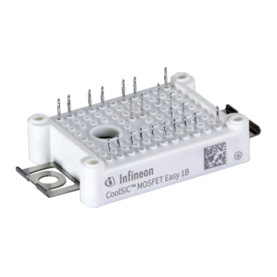
EconoPACK™ series. The Easy PressFIT pin provides a solution for modules without a baseplate. It should be noted in the case of the Easy PressFIT geometry that it has been used for decades in a wide variety of applications, and has been adapted for use in the various modules. -
Page 3: General Information On Power Module Handling
Assembly Instructions for the Easy -PressFIT Modules General information on power module handling This section describes forces on module housing – DCB push-out The power module is not designed to withstand forces on the module housing as shown in the example of Figure 3. -
Page 4: Requirements For Printed Circuit Boards
Metallization of pin Tin (galvanic) In order to ensure that the PressFIT contact sits securely in the PCB, the specification of the hole given in Table 1 must be adhered to. If the specification of PressFIT holes is limited to only the finished dimension (i.e., the metallized hole), different drill sizes could be used depending on the PCB manufacturer and production philosophy, and also different metallization thicknesses could be provided. - Page 5 A distance of 5 mm is recommended, similar to Infineon’s Econo PressFIT power modules. A PressFIT module can be replaced up to two times. This means that a PCB can be used in total three times. Correct handling of the components is essential.
-
Page 6: The Press-In Process
This section deals with the necessary press-in forces and tools for the modules. The PressFIT module is inserted in a PCB by pressing it in. PressFIT can be performed using a toggle lever press or a machine. A press-in tool that records the necessary force and the travel distance is recommended. -
Page 7: Press-In Tools For Easy Modules With Thermal Interface Material
Assembly Instructions for the Easy -PressFIT Modules Each of the tools has two parts. The first part presses against the underside of the module, and the second part holds the PCB in place to be pressed against. No components can be placed in the mounting areas of this special type of press-fitting tool. This prevents damage during the press-fitting process. - Page 8 Assembly Instructions for the Easy -PressFIT Modules Easy2B with TIM Figure 8 The structure of the presented TIM surface is only exemplary and not fixed for all products within the Easy family. The stamp should not touch the TIM material during press-in. That is why the stamp only touches the substrate areas without TIM.
-
Page 9: Press-In Forces And Speed
For Easy3B the maximum applied force should not exceed 8 kN. The press-fitting speed should not be lower than 25 mm/min according to IEC 60352-5. Infineon recommends a press-in speed of about 100 mm/min. The typical press-in speed for automated assembly lines is up to 450 mm/min. -
Page 10: The Press-Out Process
This section deals with the necessary press-out forces and tools for the modules. PressFIT modules are removed with the appropriate tools as shown in Figure 10 and Figure 11. The PCB is placed with the PressFIT module on the device tray. Force is applied with the extrusion plate on the PressFIT pins that protrude from the PCB. -
Page 11: Press-Out Forces
Assembly Instructions for the Easy -PressFIT Modules Press-out tools for Easy1B (left) and Easy2B (right) modules Figure 11 The drawing can be adjusted according to requirements and the tools produced by a manufacturer of choice. Press-out forces To press a module out of a PCB, a force of approximately >40 N has to be applied for each pin in the module. -
Page 12: Quality Of Pressfit Contacts
As an advanced technology on the market, the PressFIT makes it possible to improve reliability up to a factor of 100 compared to manually soldered contacts and other contact types. The results of the reliability analyses in the Siemens norm SN 29500-5 demonstrate the factor. - Page 13 Extract from qualification test Figure 12 Further details on the individual tests can be found in various publications, such as "Reliability of PressFIT connections" at www.infineon.com. Application Note <Revision 2.4>...
-
Page 14: Mounting A Pcb To The Module
Assembly Instructions for the Easy -PressFIT Modules Mounting a PCB to the module For mounting a PCB onto the module, additional screws can be used if desired. These screws will be tightened into the stand-offs of the module. An electronically controlled, or a slowly turning electric screwdriver, with n ≤ 300 rpm, is the preferred mounting tool. -
Page 15: Condition Of The Heat Sink For Module Assembly
Assembly Instructions for the Easy -PressFIT Modules Condition of the heat sink for module assembly The power loss occurring in the module has to be dissipated via heat sink in order not to exceed the maximum permissible temperature T specified in the datasheets during operation. -
Page 16: Applying The Thermal Grease
Assembly Instructions for the Easy -PressFIT Modules Applying the thermal grease Due to the individual surface shape (e.g. roughness and flatness) of the heat sink and the module, the lower surface of the module and the surface of heat sink do not touch across the entire area. Therefore a certain localized separation between the two components cannot be avoided. -
Page 17: Assembling The Module On Heat Sink
Assembly Instructions for the Easy -PressFIT Modules Assembling the module on heat sink Assembling Easy1B/2B module on heat sink The module is mounted onto the heat sink using M4 screws. It is also possible to use an additional flat washer. - Page 18 Assembly Instructions for the Easy -PressFIT Modules Module fastening options Figure 15 Alternatively, one screw can be applied initially. It is important that the module does not lift up. To prevent this, tighten the first screw loosely to avoid a press force to the clamp (Figure 16a). Then, tighten the second screw completely (Figure 16b).
-
Page 19: Assembling Easy3B Module On Heat Sink
As per technical literature Assembling Easy3B module on heat sink For the assembly of the Easy3B module to the heatsink, Infineon recommends the use of DIN M5 screws, in combination with a M5 washer. Position the module correctly to the heat sink, so that the mounting area of the module is congruent with the threaded holes in the heat sink. - Page 20 Assembly Instructions for the Easy -PressFIT Modules Step 1 Step 2 Step 3 Module fastening steps Figure 18 The following values are recommended for the mounting process: Table 5 Recommended parameters for heat sink mounting Description Values Mounting screw Recommended mounting torque = 1.5 Nm...
-
Page 21: System Considerations
Assembly Instructions for the Easy -PressFIT Modules System considerations If the module is correctly mounted to the heat sink and to the PCB, the screw clamps will apply the necessary pressure. This pressure, together with the correct amount of thermal grease, will ensure a low thermal resistance and an optimal thermal flow between the module and the heat sink. -
Page 22: Clearance And Creepage Distances
Assembly Instructions for the Easy -PressFIT Modules Clearance and creepage distances When defining the layout of the PCB, application specific standards, mainly regarding clearance and creepage distances, have to be considered. This is particularly important for the area of the screw clamp, which is located under the PCB. - Page 23 Assembly Instructions for the Easy -PressFIT Modules In any case, the application-specific clearance and creepage distances have to be checked and compared to relevant standards and guaranteed by suitable constructive means, if required. Application Note <Revision 2.4> <<2019-06-17>>...
-
Page 24: Multi-Module And Automotive Application
PCB or unwanted forces on the modules and PressFIT pins. Please note that the following instructions shall be regarded as additional information to the general mounting instructions. - Page 25 Assembly Instructions for the Easy -PressFIT Modules Application Note <Revision 2.4> <<2019-06-17>>...
-
Page 26: Modules And Pcb Mounting On The Heat Sink
Assembly Instructions for the Easy -PressFIT Modules Press-in of the power modules (drawing not true to scale) Figure 22 12.2 Modules and PCB mounting on the heat sink After the power module is pressed into the PCB (see Figure 23a), the PCB with the module has to be mounted to the cooling system. - Page 27 Assembly Instructions for the Easy -PressFIT Modules Mounting example of the PCB and module to the cooling system (drawing not true to scale) Figure 23 The Figure 24 shows a zoom of the final system assembly. Depending on the height of the module, a small air gap remains between module and PCB.
-
Page 28: Press-In And Mouting Only Easy3B Modules With Pcb And Heat Sink
Assembly Instructions for the Easy -PressFIT Modules Zoom illustration of final system assembly (drawing not true to scale) Figure 24 Please note that using this press concept with a remaining air gap does not allow the PCB to be screwed down to the stand-offs (guiding holes) as shown in chapter 6. - Page 29 Assembly Instructions for the Easy -PressFIT Modules In Figure 26a, the Easy3B module(s) is pressed into the PCB. Figure 26b shows the process where the PCB with the pre-assembled modules is placed on the cooling system, and the modules are fixed with screws. Please refer to Chapter 9.2 for detailed information on assembly of the Easy3B modules on the heat sink.
- Page 30 Assembly Instructions for the Easy -PressFIT Modules Revision History Major changes since the last revision Page or reference Description of change Chapter 3.1 Insertion of illustration about press-in tools for Easy3B Chapter 9.2 Insertion of assemblying Easy3B module on heatsink Chapter 12.3...
- Page 31 Infineon Technologies hereby disclaims dangerous substances. For information on the types any and all warranties and liabilities of any kind in question please contact your nearest Infineon (including without limitation warranties of non- © 2019 Infineon Technologies AG. Technologies office.
Need help?
Do you have a question about the PressFIT and is the answer not in the manual?
Questions and answers