
Related Manuals for Infineon GTM TIM Capture 1


Summary of Contents for Infineon GTM TIM Capture 1
- Page 1 GTM_TIM_Capture_1 PWM input capturing via TIM AURIX™ TC2xx Microcontroller Training V1.0.0 Please read the Important Notice and Warnings at the end of this document...
-
Page 2: Scope Of Work
The TIM is used in capture mode. The data from the captured PWM signal is used to calculate the PWM signal frequency and duty cycle in software. The frequency and the duty cycle are then stored in variables. 2020-01-17 Copyright © Infineon Technologies AG 2020. All rights reserved. - Page 3 The Clock Management Unit (CMU) is responsible for clock generation of the GTM. The Configurable Clock Generation Subunit (CFGU) provides eight clock sources for the GTM submodules: TIM, TBU, MON and ATOM. 2020-01-17 Copyright © Infineon Technologies AG 2020. All rights reserved.
- Page 4 The Clock Management Unit (CMU) is responsible for clock generation of the GTM. The Fixed Clock Generation (FXU) is one of its subunits and it provides five predefined non-configurable clocks for GTM modules, including the TOM. 2020-01-17 Copyright © Infineon Technologies AG 2020. All rights reserved.
-
Page 5: Hardware Setup
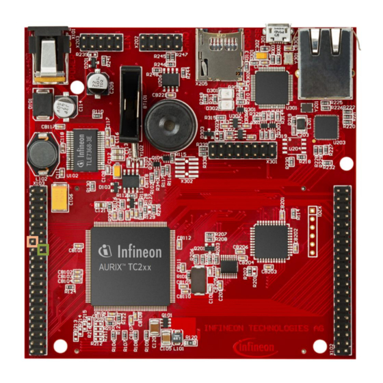
Hardware setup This code example has been developed for the board KIT_AURIX_TC297_TFT_BC-Step. Connect the TIM input port pin P02.0 with the TOM output port pin P02.3. 2020-01-17 Copyright © Infineon Technologies AG 2020. All rights reserved. - Page 6 After setting the configuration parameters, the function IfxGtm_Tim_In_init() applies the user configuration to the module All the functions used for the configuration of the TIM are provided by the iLLD header IfxGtm_Tim_In.h. 2020-01-17 Copyright © Infineon Technologies AG 2020. All rights reserved.
- Page 7 – Selection of the output port pin – synchronousUpdateEnable – Enabling of Synchronous Update of the timer – clock – Selection of the clock used for the generation of the PWM 2020-01-17 Copyright © Infineon Technologies AG 2020. All rights reserved.
- Page 8 › Start the PWM with the function IfxGtm_Tom_Pwm_start() All the functions used for the configuration of the TOM are provided by the iLLD header IfxGtm_Tom_Pwm.h. 2020-01-17 Copyright © Infineon Technologies AG 2020. All rights reserved.
- Page 9 In this example: ������������ = = 50000 ���������� ⇒ 8 ���� 125 ���� FXU clock 1 Frequency of the clock PWM signal Period of PWM Duty cycle of the PWM 2020-01-17 Copyright © Infineon Technologies AG 2020. All rights reserved.
- Page 10 Calculate the PWM frequency with the formula: frequency(Hz) = 1 / period(s) › Get the PWM duty cycle by calling the iLLD function IfxGtm_Tim_In_getDutyPercent() All the iLLD functions above are provided by the iLLD header IfxGtm_Tim_In.h 2020-01-17 Copyright © Infineon Technologies AG 2020. All rights reserved.
- Page 11 After code compilation and flashing the device, perform the following steps: › Add the variables g_measuredPwmFreqHz and g_measuredDutyCycle to the Watch Expressions on the debugger › Suspend the program to check the value of the variables 2020-01-17 Copyright © Infineon Technologies AG 2020. All rights reserved.
- Page 12 More code examples can be found on the GIT repository: › https://github.com/Infineon/AURIX_code_examples › For additional trainings, visit our webpage: › https://www.infineon.com/aurix-expert-training › For questions and support, use the AURIX™ Forum: › https://www.infineonforums.com/forums/13-Aurix-Forum 2020-01-17 Copyright © Infineon Technologies AG 2020. All rights reserved.
- Page 13 Infineon Technologies in in personal injury. customer’s applications. The data contained in this document is exclusively intended for technically trained staff.
Need help?
Do you have a question about the GTM TIM Capture 1 and is the answer not in the manual?
Questions and answers