
Related Manuals for Infineon ASCLIN LIN Master 1


Summary of Contents for Infineon ASCLIN LIN Master 1
- Page 1 ASCLIN_LIN_Master_1 LIN master communication via ASCLIN module AURIX™ TC2xx Microcontroller Training V1.0.0 Please read the Important Notice and Warnings at the end of this document...
-
Page 2: Scope Of Work
An ASCLIN module is configured as LIN master to send “Hello World!” The string “Hello World!” is sent via an ASCLIN module configured as LIN master. The signal can be visualized using an oscilloscope. 2019-10-17 Copyright © Infineon Technologies AG 2019. All rights reserved. - Page 3 A LIN frame consists of two parts: – The header, which is always sent by the LIN Master – The response, which is sent either by the LIN Master or the addressed LIN Slave 2019-10-17 Copyright © Infineon Technologies AG 2019. All rights reserved.
-
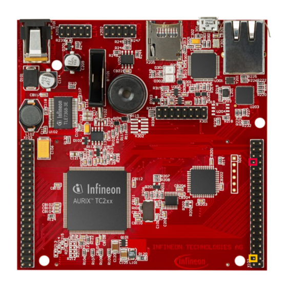
Page 4: Hardware Setup
Hardware setup This code example has been developed for the board KIT_AURIX_TC297_TFT_BC-Step. The port pin P15.5 (LIN-TX/RX) should be connected to an oscilloscope probe. TX/RX Ground 2019-10-17 Copyright © Infineon Technologies AG 2019. All rights reserved. - Page 5 The pin configuration is set using the predefined structure IfxAsclin_Lin_Pins. The ASCLIN module is initialized with IfxAsclin_Lin_initModule(). All functions required for the configuration of the ASCLIN module are provided by the iLLD header IfxAsclin_Lin.h. 2019-10-17 Copyright © Infineon Technologies AG 2019. All rights reserved.
- Page 6 The transmission of header is checked by using the parameter txHeaderEnd of the structure acknowledgmentFlags. The frame is sent with the function IfxAsclin_Lin_sendResponse(). The functions above are provided by the iLLD header IfxAsclin_Lin.h. 2019-10-17 Copyright © Infineon Technologies AG 2019. All rights reserved.
- Page 7 › Connect the oscilloscope probe to the TX/RX pin (P15.5) › Reset and run the program by pressing the PORST push button › Check the oscilloscope for the LIN signal: 2019-10-17 Copyright © Infineon Technologies AG 2019. All rights reserved.
- Page 8 Run and Test › In the signal both the header and the frame „Hello World!“ can be observed: › Header › Frame „Hello World!“ 2019-10-17 Copyright © Infineon Technologies AG 2019. All rights reserved.
- Page 9 More code examples can be found on the GIT repository: › https://github.com/Infineon/AURIX_code_examples › For additional trainings, visit our webpage: › https://www.infineon.com/aurix-expert-training › For questions and support, use the AURIX™ Forum: › https://www.infineonforums.com/forums/13-Aurix-Forum 2019-10-17 Copyright © Infineon Technologies AG 2019. All rights reserved.
- Page 10 Infineon Technologies in in personal injury. customer’s applications. The data contained in this document is exclusively intended for technically trained staff.
Need help?
Do you have a question about the ASCLIN LIN Master 1 and is the answer not in the manual?
Questions and answers