
Subscribe to Our Youtube Channel
Related Manuals for Infineon GPT12 PWM Capture 1


Summary of Contents for Infineon GPT12 PWM Capture 1
- Page 1 GPT12_PWM_Capture_1 Capture of PWM signal via GPT12 AURIX™ TC2xx Microcontroller Training V1.0.0 Please read the Important Notice and Warnings at the end of this document...
-
Page 2: Scope Of Work
GPT12 timers are configured in capture mode. The data from the captured PWM signal is used to calculate the PWM frequency in software. The frequency is then stored in a variable. 2019-10-17 Copyright © Infineon Technologies AG 2019. All rights reserved. - Page 3 Additionally, timer T2 and T4 can be used as capture or reload registers for the core timer T3. › In this example, Timer T2 (Capture Mode) captures the value of timer T3 (Timer Mode). 2019-10-17 Copyright © Infineon Technologies AG 2019. All rights reserved.
-
Page 4: Hardware Setup
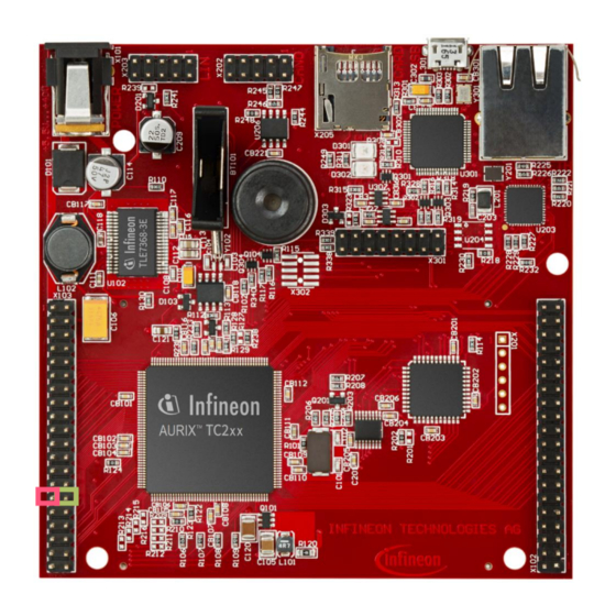
This code example has been developed for the board KIT_AURIX_TC297_TFT_BC-Step. Connect the two pins P00.8 (PWM signal) and P00.7 (GPT1 T2 input) to each other. input pin A of PWM signal timer T2 2019-10-17 Copyright © Infineon Technologies AG 2019. All rights reserved. - Page 5 The capture event is configured to be on the rising edge of the input pin with the function IfxGpt12_T2_setCaptureInputMode(). › IfxGpt12_T3_run() starts the core timer T3. The functions above are provided by the iLLD header IfxGpt12.h. 2019-10-17 Copyright © Infineon Technologies AG 2019. All rights reserved.
- Page 6 The above mentioned functions are provided by the iLLD header IfxSrc.h. › The method implementing the ISR needs to be assigned a priority and a CPU core responsible for its execution. This is done with the macro IFX_INTERRUPT(isr, vectabNum, priority). 2019-10-17 Copyright © Infineon Technologies AG 2019. All rights reserved.
- Page 7 Interrupt on each rising edge: Period of timer T3 overflow T3 Count (value is incremented with frequency of timer T3) Period of PWM signal PWM Signal 2019-10-17 Copyright © Infineon Technologies AG 2019. All rights reserved.
- Page 8 Overflow of timer T3 after ≈ 0.0026 s (65535 * 40 ns) which equals ≈ 381 Hz. › The total amount of increments can be calculated by comparing the current value of timer T2 with the value of timer T2 one PWM period ago e.g. 1000. 2019-10-17 Copyright © Infineon Technologies AG 2019. All rights reserved.
- Page 9 Calculation of the PWM frequency by dividing the frequency of timer T3 by the total amount of increments during one PWM period: – 25 MHz / 500000 = 50 Hz 2019-10-17 Copyright © Infineon Technologies AG 2019. All rights reserved.
- Page 10 (between 0 and 65535) PWM Signal (50 Hz) Period of PWM signal 0.02 s 7 overflows of timer T3 during one PWM period Interrupt on previous rising edge Interrupt on actual rising edge 2019-10-17 Copyright © Infineon Technologies AG 2019. All rights reserved.
- Page 11 For changing the frequency of the PWM signal the global parameter g_generatedPwmFreqHz can be modified. The calculation of the two timeout values for toggling the pin state is done by software. 2019-10-17 Copyright © Infineon Technologies AG 2019. All rights reserved.
- Page 12 Check parameter g_measuredPwmFreqHz in the debugger. Its value should be similar to the parameter g_generatedPwmFreqHz. Change the parameter g_generatedPwmFreqHz and check if g_measuredPwmFreqHz changes accordingly. PWM signal input pin A of timer T2 2019-10-17 Copyright © Infineon Technologies AG 2019. All rights reserved.
- Page 13 More code examples can be found on the GIT repository: › https://github.com/Infineon/AURIX_code_examples › For additional trainings, visit our webpage: › https://www.infineon.com/aurix-expert-training › For questions and support, use the AURIX™ Forum: › https://www.infineonforums.com/forums/13-Aurix-Forum 2019-10-17 Copyright © Infineon Technologies AG 2019. All rights reserved.
- Page 14 Infineon Technologies in in personal injury. customer’s applications. The data contained in this document is exclusively intended for technically trained staff.
Need help?
Do you have a question about the GPT12 PWM Capture 1 and is the answer not in the manual?
Questions and answers