Table of Contents
Advertisement
complements
INDEX
By Section
Product
Product Name
Code
HEIGHT ADJUSTABLE TABLES
COMPLEMENTS
Rectangular - Increment
YHRE
Rectangular with Split Surface - Increm. YHRS
Corner- Increment
YHCC
Corner with Split Surface - Increment
YHCS
Rectangular - Top Surface Crank
YHRE
Rectangular with Split Surface - Top
Surface Crank
YHRS
Corner- Top Surface Crank
YHCC
Rectangular - Standard Range Electric
YHRE
Rectangular with Split Surface -
Standard Range Electric
YHRS
Corner - Standard Range Electric
YHCC
Corner with Split Surface - Standard
Range Electric
YHCS
Rectangular - Standard Range Electric
YHRE
Rectangular with Split Surface -
Standard Range Electric
YHRS
Corner - Standard Range Electric
YHCC
Corner with Split Surface - Standard
Range Electric
YHCS
E- Chain Vertical Wire Manager
YEEC
Journal E-Chain
YEEC
E-Chain Vertical Wire Manager for Navigate for upStage built-in
YEEE
E-Chain Vertical Wire Manager for Journal YEEE
E-Chain Vertical Wire Manager for Navigate, hiSpace and complements
YEEE
E-Chain Vertical Wire Manager for HAB for Navigate
YEEE
Modesty Panel
YHMP
Wire Tray
YHWT
Height Adjustable Table Casters kit
YHCA
Jan 2020
*Click on the desired Installation Guide to jump to the Guide
page.
Guide
Last
No.
Updated
Product Name
LIVELLO
Table adjustment - Standard Switch
101a
Sept 2017
Table adjustment with Display Switch
Table adjustment with Logic Data
Livello Height Adjustable Table -
Extended Corner - Standard Range Elec.
101b
May 2018
Extended Corner - Extended Range Elec.
Livello Height Adjustable Workstation
Table - Standard Range Electric
Livello Height Adjustable Workstation
101c
Jan 2018
Table - Extended Range Electric
Livello Height Adjustable Table - Corner
Standard Range Electric
Extended Range Electric
Freestanding
Livello Height Adjustable Table - Corner
101d
Sept 2019
Top Surface Crank
Worstation Table Top Surface Crank
Freestanding Top Surface Crank
Livello Height Adjustable Workstation
Table - Counterbalance
Freestanding - Counterbalance
102a
Sept 2017
Upstage Integrated Height Adjustable
102b
Sept 2017
Table
102c
Sept 2018
Upstage Freestanding Height
102d
Sept 2018
Adjustable Table
102e
Sept 2018
Standard Mount Cable Tray
102f
Jan 2019
Modesty Mount Cable Tray
103a
Sept 2017
Modesty Panel
103b
Sept 2017
104
Sept 2018
Product
Guide
Last
Code
No.
Updated
Product Name
HISPACE
NO-CODE 111a
Sept 2017
HiSpace Height Adjustable Table -
NO-CODE 111b
Sept 2017
Recatangle - Electric
NO-CODE 111c
Sept 2017
HiSpace Height Adjustable Table -
Base - Electric
112
Sept 2017
HiSpace Height Adjustable Table -
LVER
Integrated - Electric
LVER
HiSpace Height Adjustable Table -
113
Sept 2017
Freestanding - Electric
LVWR
HiSpace Height Adjustable Table -
Recatangle - Under Worksurface Crank YSRE
LVWR
HiSpace Height Adjustable Table -
Base - Under Worksurface Crank
LVCC
HiSpace Height Adjustable Table -
LVCC
Integrated - Under Worksurface Crank YSHT
LVFD
HiSpace Height Adjustable Table -
114
Sept 2017
Freestanding - Under Worksurface CrankYSHU
LVCC
Worksurface Wire Loom
LVWR
LVFD
115
Sept 2019
LVWR
LVFD
LVHT
LVHU
116
Sept 2017
LVCTS
LVCTM
UNSM
Product
Guide
Last
Code
No.
Updated
Dec 2019
130
YSRE
YSYS
YSHT
YSHU
131
Sept 2017
YSYS
132
Sept 2017
YESL
PAGE 1 OF 3
Advertisement
Table of Contents

Related Manuals for Teknion Complements Series


Summary of Contents for Teknion Complements Series
- Page 1 complements INDEX *Click on the desired Installation Guide to jump to the Guide By Section page. Product Guide Last Product Guide Last Product Guide Last Product Name Code Updated Product Name Code Updated Product Name Code Updated HEIGHT ADJUSTABLE TABLES LIVELLO HISPACE COMPLEMENTS...
- Page 2 complements INDEX *Click on the desired Installation Guide to jump to the Guide By Section page. Product Guide Last Product Guide Last Product Guide Last Product Name Code Updated Product Name Code Updated Product Name Code Updated NAVIGATE ERGONOMIC ACCESSORIES ERGONOMIC ACCESSORIES Counterbalance Dual Arm Keyboard Support...
- Page 3 complements INDEX *Click on the desired Installation Guide to jump to the Guide By Section page. Product Guide Last Product Guide Last Product Name Code Updated Product Name Code Updated LIGHTING ELECTRICAL NO INSTALLATION GUIDE Conflux Desk Lamps 403b Sept 2017 Electrical Height Adjustable Accessory Combo YLCB...
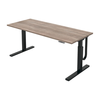
- Page 4 complements Installation Guides Section: HEIGHT ADJUSTABLE TABLES (COMPLEMENTS) Date: Sept 2017 Page No: 1 of 3 Description: HEIGHT ADJUSTABLE TABLE - INCREMENT COM_101a Rev. No: 2 Rectangular - Increment(YHRE), Part and Product Identification Rectangular with Split Surface - Increment (YHRS), Corner - Increment (YHCC), Corner with Split Surface - Increment (YHCS) A - Modesty Brace Assembly (N09-5758) x1...
- Page 5 complements Installation Guides Section: HEIGHT ADJUSTABLE TABLES (COMPLEMENTS) Date: Sept 2017 Page No: 2 of 3 Description: HEIGHT ADJUSTABLE TABLE - INCREMENT COM_101a CONNECT LEGS DETAIL 1 STEP 1: Connect Legs with Leg Connecting Bar. Secure with hardware. INSTALL TABLE TOP DETAIL 2 3.5"...
-
Page 6: Adjust Height
complements Installation Guides Section: HEIGHT ADJUSTABLE TABLES (COMPLEMENTS) Date: Sept 2017 Page No: 3 of 3 Description: HEIGHT ADJUSTABLE TABLE - INCREMENT COM_101a REMOVE SCREWS AND WASHERS ADJUST HEIGHT STEP 3: Remove screws and washers. STEP 4: Push worksurface up to desire height. SECURE HEIGHT NOTES STEP 5: Replace screws and washers. - Page 7 complements Installation Guides Section: HEIGHT ADJUSTABLE TABLES (COMPLEMENTS) Date: May 2018 Page No: 1 of 4 Description: HEIGHT ADJUSTABLE TABLE - TOP SURFACE CRANK COM_101b Rev. No: 4 Rectangular - Top Surface Crank (YHRE), Rectangular with Split Surface - Top Part and Product Identification Surface Crank (YHRS), Corner -Top Surface Crank (YHCC), Corner with Split Surface - Top Surface Crank (YHCS)
-
Page 8: Base Assembly
complements Installation Guides Section: HEIGHT ADJUSTABLE TABLES (COMPLEMENTS) Date: May 2018 Page No: 2 of 4 Description: HEIGHT ADJUSTABLE TABLE - TOP SURFACE CRANK COM_101b BASE ASSEMBLY INSERT BUSHING STEP 1: Place Base Assembly on Floor. WORKSURFACE B = 9" 30"... - Page 9 complements Installation Guides Section: HEIGHT ADJUSTABLE TABLES (COMPLEMENTS) Date: May 2018 Page No: 3 of 4 Description: HEIGHT ADJUSTABLE TABLE - TOP SURFACE CRANK COM_101b PLACE WORKSURFACE ON BASE ASSEMBLY FASTEN WORKSURFACE STEP 5: After proper placement of the Worksurafce, Fasten it with the Wood Screws provided. INSTALL CRANK HANDLE HOLDER STEP 4: Place Worksuarface on Base Assembly.
- Page 10 complements Installation Guides Section: HEIGHT ADJUSTABLE TABLES (COMPLEMENTS) Date: May 2018 Page No: 4 of 4 Description: HEIGHT ADJUSTABLE TABLE - TOP SURFACE CRANK COM_101b INSTALL CRANK HANDLE STORE CRANK HANDLE STEP 7: Insert Crank Handle Bushing and Crank Handle. Test Table function and level. REMOVE CRANK HANDLE When Crank Handle is not in use, store it inside Handle...
- Page 11 complements Installation Guides Section: HEIGHT ADJUSTABLE TABLES (COMPLEMENTS) Date: Jan 2018 Page No: 1 of 4 Description: HEIGHT ADJUSTABLE TABLE - STANDARD & EXTENDED RANGE ELECTRIC COM_101c Rev. No: 7 Rectangular - Std./Ext. Range Electric (YHRE), Part and Product Identification Rectangular with Split Surface - Std./Ext.
- Page 12 complements Installation Guides Section: HEIGHT ADJUSTABLE TABLES (COMPLEMENTS) Date: Jan 2018 Page No: 2 of 4 Description: HEIGHT ADJUSTABLE TABLE - STANDARD & EXTENDED RANGE ELECTRIC COM_101c INSTALL LEVELER OR CASTER NOTE: Proceed with this step NOTE: Proceed with this step ONLY if Caster is specified.
- Page 13 complements Installation Guides Section: HEIGHT ADJUSTABLE TABLES (COMPLEMENTS) Date: Jan 2018 Page No: 3 of 4 Description: HEIGHT ADJUSTABLE TABLE - STANDARD & EXTENDED RANGE ELECTRIC COM_101c INSTALL CONNECTING BAR SECURE CONNECTING BAR STEP 2: Attach Legs Connecting Bar to Legs. STEP 3: Secure in place using Machine Screws and Washers.
- Page 14 complements Installation Guides Section: HEIGHT ADJUSTABLE TABLES (COMPLEMENTS) Date: Jan 2018 Page No: 4 of 4 Description: HEIGHT ADJUSTABLE TABLE - STANDARD & EXTENDED RANGE ELECTRIC COM_101c INSTALL ELECTRICS INSTALL CABLE MANAGEMENT STEP 6: Attach Switch to the underside of the Table Top using pre drilled holes for location. STEP 7: Peel the tape off from Cable Management units.
- Page 15 complements Installation Guides Section: HEIGHT ADJUSTMENT TABLES (COMPLEMENTS) Date: Sept 2019 Page No: 1 of 16 Description: HEIGHT ADJUSTMENT TABLE - COUNTER - BALANCE - TROUBLE SHOOTING COM_101d Rev. No: 6 Rectangular - Counter-Balance (YHRE), Rectangular with Split Part and Product Identification Surface - Counter-Balance (YHRS), Corner - Counter-Balance (YHCC), Corner with Split Surface - Counter-Balance (YHCS) A - H Frame...
-
Page 16: Attach Feet
complements Installation Guides Section: HEIGHT ADJUSTMENT TABLES (COMPLEMENTS) Date: Sept 2019 Page No: 2 of 16 Description: HEIGHT ADJUSTMENT TABLE - COUNTER - BALANCE - TROUBLE SHOOTING COM_101d INSTALL STRUTS ATTACH FEET NOTE: H-Frame up-side-down. STEP 1: Install Struts on H-Frame with Screws as shown. STEP 2: Flip H-Frame up-side-down. - Page 17 complements Installation Guides Section: HEIGHT ADJUSTMENT TABLES (COMPLEMENTS) Date: Sept 2019 Page No: 3 of 16 Description: HEIGHT ADJUSTMENT TABLE - COUNTER - BALANCE - TROUBLE SHOOTING COM_101d WORKSURFACE ASSEMBLY STEP 3: Keep H-Frame and Worksurface up-side-down. Align pilot holes on Struts with the Worksurface as shown, then secure them with Screws.
-
Page 18: Paddle Assembly
complements Installation Guides Section: HEIGHT ADJUSTMENT TABLES (COMPLEMENTS) Date: Sept 2019 Page No: 4 of 16 Description: HEIGHT ADJUSTMENT TABLE - COUNTER - BALANCE - TROUBLE SHOOTING COM_101d PADDLE ASSEMBLY ATTACH HANDLE HOLDER NOTE: Please refer to Specification Drawing for location to install Paddle. Paddle installing on right handed side of the Table shown. - Page 19 complements Installation Guides Section: HEIGHT ADJUSTMENT TABLES (COMPLEMENTS) Date: Sept 2019 Page No: 5 of 16 Description: HEIGHT ADJUSTMENT TABLE - COUNTER - BALANCE - TROUBLE SHOOTING COM_101d INSERT HANDLE STORE HANDLE Underside View NOTE: Please refer to Operation Guides for Table height adjustment instructions.
- Page 20 complements Installation Guides Section: HEIGHT ADJUSTMENT TABLES (COMPLEMENTS) Date: Sept 2019 Page No: 6 of 16 Description: HEIGHT ADJUSTMENT TABLE - COUNTER - BALANCE - TROUBLE SHOOTING COM_101d LEVELING INSERT GROMMET & ATTACH E-CHAIN LEVELER If E-Chain is specified, please refer to Installation Guide No.
- Page 21 complements Installation Guides Section: HEIGHT ADJUSTMENT TABLES (COMPLEMENTS) Date: Sept 2019 Page No: 7 of 16 Description: HEIGHT ADJUSTMENT TABLE - COUNTER - BALANCE - TROUBLE SHOOTING COM_101d BRACKET INSTALLATION (WITH GROMMET) BRACKET INSTALLATION ( WITHOUT GROMMET) STEP 10a: Use provided self-tap Screws to fasten Brackets under the Worksurface. STEP 10b: Use provided self-tap Screws to fasten Brackets under the Worksurface.
-
Page 22: Side View
complements Installation Guides Section: HEIGHT ADJUSTMENT TABLES (COMPLEMENTS) Date: Sept 2019 Page No: 8 of 16 Description: HEIGHT ADJUSTMENT TABLE - COUNTER - BALANCE - TROUBLE SHOOTING COM_101d SIDE VIEW FRONT VIEW (TABLE WITH GROMMET) FRONT VIEW (TABLE WITHOUT GROMMMET) NOTE: Make sure the Bracket will not interfere with the Cross Bar on the H-frame. - Page 23 complements Installation Guides Section: HEIGHT ADJUSTMENT TABLES (COMPLEMENTS) Date: Sept 2019 Page No: 9 of 16 Description: HEIGHT ADJUSTMENT TABLE - COUNTER - BALANCE - TROUBLE SHOOTING COM_101d ATTACH POWER BAR (WITH GROMMET) ATTACH POWER BAR ( WITHOUT GROMMET) Underside View Underside View STEP 11: Attach Power Bar into the Bracket as shown.
- Page 24 complements Installation Guides Section: HEIGHT ADJUSTMENT TABLES (COMPLEMENTS) Date: Sept 2019 Page No: 10 of 16 Description: HEIGHT ADJUSTMENT TABLE - COUNTER - BALANCE - TROUBLE SHOOTING COM_101d SIDE VIEW FRONT VIEW (TABLE WITH GROMMET) NOTE: The Bracket should be clipped at the center of Power Bar. FRONT VIEW (TABLE WITHOUT GROMMET) Detail View NOTE: Make sure the Power Bar is fully clipped into the Bracket.
- Page 25 complements Installation Guides Section: HEIGHT ADJUSTMENT TABLES (COMPLEMENTS) Date: Sept 2019 Page No: 11 of 16 Description: HEIGHT ADJUSTMENT TABLE - COUNTER - BALANCE - TROUBLE SHOOTING COM_101d WIRING (TABLE WITH GROMMET) Underside View STEP 12a: Please refer to the above diagram for Cable routing for Table with Grommet.
- Page 26 complements Installation Guides Section: HEIGHT ADJUSTMENT TABLES (COMPLEMENTS) Date: Sept 2019 Page No: 12 of 16 Description: HEIGHT ADJUSTMENT TABLE - COUNTER - BALANCE - TROUBLE SHOOTING COM_101d WIRING (TABLE WITHOUT GROMMET) Underside View STEP 12b: Please refer to the above diagram for Cable routing for Table without Grommet.
- Page 27 complements Installation Guides Section: HEIGHT ADJUSTMENT TABLES (COMPLEMENTS) Date: Sept 2019 Page No: 13 of 16 Description: HEIGHT ADJUSTMENT TABLE - COUNTER - BALANCE - TROUBLE SHOOTING COM_101d COUNTER-BALANCE ADJUSTMENT (INITIAL SET-UP) CHARGING INSTRUCTIONS: 1. INSTALL THE TABLE WORKSURFACE. 2. PRESS AND HOLD THE RELEASE PEDAL. 3.
- Page 28 complements Installation Guides Section: HEIGHT ADJUSTMENT TABLES (COMPLEMENTS) Date: Sept 2019 Page No: 14 of 16 Description: HEIGHT ADJUSTMENT TABLE - COUNTER - BALANCE - TROUBLE SHOOTING COM_101d PRESS TABLE USING RELEASE MECHANISM NOTE: Rotate Counter-Balance Adjustment Handle toward "-" if it's too tight, rotate toward "+"...
-
Page 29: Adding Weight
complements Installation Guides Section: HEIGHT ADJUSTMENT TABLES (COMPLEMENTS) Date: Sept 2019 Page No: 15 of 16 Description: HEIGHT ADJUSTMENT TABLE - COUNTER - BALANCE - TROUBLE SHOOTING COM_101d ADJUST HEIGHT ADDING WEIGHT NOTE: Worksurface should be easy to move up and down. Please refer to Step 2 on Page 8 to add or release pressure on Counter-Balance if necessary. - Page 30 3. Improper use and set up will impact the warranty. 4. If the product is not functioning properly after Troubleshooting, please contact your authorized Teknion dealer. Maximum load for the table is 120 lbs. excluding the Worksurface.
- Page 31 complements Installation Guides Section: HEIGHT ADJUSTABLE TABLES Date: Sept 2017 Page No: 1 of 7 Description: COMPLEMENTS, LIVELLO & ABILITY E-CHAIN VERTICAL WIRE MANAGER COM_102a Rev. No: 2 E-Chain (YEEC) Part and Product Identification A1 - E-Chain x1 A1 - E-Chain x1 A2 - E-Chain (B02-0514) x1 Bottom Link...
- Page 32 complements Installation Guides Section: HEIGHT ADJUSTABLE TABLES Date: Sept 2017 Page No: 2 of 7 Description: COMPLEMENTS, LIVELLO & ABILITY E-CHAIN VERTICAL WIRE MANAGER COM_102a INSTALL E-CHAIN Push Cable inside E-Chain STEP 1: Insert Cables through E-Chain and secure cables with Cable Tie Wrap. Lower assembly to Wire Manager Cover and snap in place.
- Page 33 complements Installation Guides Section: HEIGHT ADJUSTABLE TABLES Date: Sept 2017 Page No: 3 of 7 Description: COMPLEMENTS, LIVELLO & ABILITY E-CHAIN VERTICAL WIRE MANAGER COM_102a INSTALL E-CHAIN COVER Side View Side View Finished Finished Floor Floor Wire Manager Cover STEP 2: Attach Wire Cover at an angle. Install bottom portion of Wire Cover First and then install top portion of Wire Cover.
- Page 34 complements Installation Guides Section: HEIGHT ADJUSTABLE TABLES Date: Sept 2017 Page No: 4 of 7 Description: COMPLEMENTS, LIVELLO & ABILITY E-CHAIN VERTICAL WIRE MANAGER COM_102a INSTALL E-CHAIN STEP 3: Secure cables with Cable Tie Wrap. Install Clip as shown and fasten with Screws provided.
- Page 35 complements Installation Guides Section: HEIGHT ADJUSTABLE TABLES Date: Sept 2017 Page No: 5 of 7 Description: COMPLEMENTS, LIVELLO & ABILITY E-CHAIN VERTICAL WIRE MANAGER COM_102a INSTALL E-CHAIN STEP 4: Secure cables with Cable Tie Wrap. Install Clips as shown and fasten with Screws provided.
- Page 36 complements Installation Guides Section: HEIGHT ADJUSTABLE TABLES Date: Sept 2017 Page No: 6 of 7 Description: COMPLEMENTS, LIVELLO & ABILITY E-CHAIN VERTICAL WIRE MANAGER COM_102a E-CHAIN HAS TO BE STRAIGHT CORRECT INSTALLATION DETAIL...
- Page 37 complements Installation Guides Section: HEIGHT ADJUSTABLE TABLES Date: Sept 2017 Page No: 1 of 2 Description: JOURNAL E-CHAIN VERTICAL WIRE MANAGER COM_102b Rev. No: 1 Journal E-Chain (YEEC) Part and Product Identification A1 - E-Chain A2 - E-Chain (B02-0514) x1 Bottom Link (B02-0541) x1 A4 - Cable Manager...
- Page 38 complements Installation Guides Section: HEIGHT ADJUSTABLE TABLES Date: Sept 2017 Page No: 2 of 2 Description: JOURNAL E-CHAIN VERTICAL WIRE MANAGER COM_102b INSTALL E-CHAIN Back of Post Location Push Cable inside E-Chain Side of Post Location STEP 1: Insert Cables through E-Chain and secure cables with Cable Tie Wrap. Lower assembly to Wire Manager Cover and snap in place. Install Links as shown and fasten with Screws provided.
- Page 39 complements Installation Guides Section: H.A.TABLES ACCESSORIES Date: Sept 2018 Page No: 1 of 3 Description: E-CHAIN VERTICAL WIRE MANAGER COM_102c Rev. No: 0 Navigate Built-In Stage E-Chain Vertical Wire Manager (YEEE11) Part and Product Identification A1 - E-Chain Assembly N09-5693 x1 A2 - E-Chain Mounting Bracket Navigate Upstage A16-7047 x1...
-
Page 40: Wire Management
complements Installation Guides Section: H.A.TABLES ACCESSORIES Date: Sept 2018 Page No: 2 of 3 Description: E-CHAIN VERTICAL WIRE MANAGER COM_102c REMOVE STAGE COVER WIRE MANAGEMENT STEP 1: The Cover of the Built-In Stage should be removed in order to attach the Wire Manager. - Page 41 complements Installation Guides Section: H.A.TABLES ACCESSORIES Date: Sept 2018 Page No: 3 of 3 Description: E-CHAIN VERTICAL WIRE MANAGER COM_102c INSTALL THE E-CHAIN MOUNTING BRACKET WIRE MANAGEMENT STEP 5: Attach the Retainer Clip onto the E-Chain assembly and mount the whole assembly to the Pilot holes on the Built-In Stage using two wood screws and tie the wire with cable tie and pull excess wire through the Grommet on the Built-In Stage.
- Page 42 complements Installation Guides Section: H.A. TABLES ACCESSORIES Date: Sept 2018 Page No: 1 of 2 Description: E-CHAIN VERTICAL WIRE MANAGER COM_102d Rev. No: 1 Journal E-Chain (YEEE06) Part and Product Identification A1 - E-Chain Assembly (B02-05637) x1 A2 - E-Chain Bottom Link (B02-0541) x1 A3 - E-Chain Top Link (B02-0542) x1...
- Page 43 complements Installation Guides Section: H.A. TABLES ACCESSORIES Date: Sept 2018 Page No: 2 of 2 Description: E-CHAIN VERTICAL WIRE MANAGER COM_102d INSTALL E-CHAIN Back of Post Location Push Cable inside E-Chain Side of Post Location STEP 1: Insert Cables through E-Chain and secure cables with Cable Tie Wrap. Lower assembly to Wire Manager Cover and snap in place. Install Links as shown and fasten with Screws provided.
- Page 44 complements Installation Guides Section: H.A. TABLES ACCESSORIES Date: Sept 2018 Page No: 1 of 6 Description: COMPLEMENTS, NAVIGATE & hiSPACE E-CHAIN VERTICAL WIRE MANAGER COM_102e Rev. No: 2 E-Chain Vertical Wire Manager (YEEE01), (YEEE02), (YEEE03), (YEEE07), Part and Product Identification (YEEE08), (YEEE10) and (YEEE12) A1 - E-Chain x1 A1 - E-Chain x1...
- Page 45 complements Installation Guides Section: H.A.TABLES ACCESSORIES Date: Sept 2018 Page No: 2 of 6 Description: COMPLEMENTS, NAVIGATE & hiSPACE E-CHAIN VERTICAL WIRE MANAGER COM_102e INSTALL E-CHAIN Push Cable inside E-Chain STEP 1: Insert Cables through E-Chain and secure cables with Cable Tie Wrap. Lower assembly to Wire Manager Cover and snap in place.
- Page 46 complements Installation Guides Section: H.A.TABLES ACCESSORIES Date: Sept 2018 Page No: 3 of 6 Description: COMPLEMENTS, NAVIGATE & hiSPACE E-CHAIN VERTICAL WIRE MANAGER COM_102e INSTALL E-CHAIN COVER Side View Side View Finished Finished Floor Floor Wire Manager Cover STEP 2: Attach Wire Cover at an angle. Install bottom portion of Wire Cover First and then install top portion of Wire Cover.
- Page 47 complements Installation Guides Section: H.A.TABLE ACCESSORIES Date: Sept 2018 Page No: 4 of 6 Description: COMPLEMENTS, NAVIGATE & hiSPACE E-CHAIN VERTICAL WIRE MANAGER COM_102e INSTALL E-CHAIN STEP 3: Secure cables with Cable Tie Wrap. Install Clip as shown and fasten with Screws provided.
- Page 48 complements Installation Guides Section: H.A.TABLES ACCESSORIES Date: Sept 2018 Page No: 5 of 6 Description: COMPLEMENTS, NAVIGATE & hiSPCAE E-CHAIN VERTICAL WIRE MANAGER COM_102e INSTALL E-CHAIN STEP 4: Secure cables with Cable Tie Wrap. Install Clips as shown and fasten with Screws provided.
- Page 49 complements Installation Guides Section: H.A.TABLES ACCESSORIES Date: Sept 2018 Page No: 6 of 6 Description: COMPLEMENTS, NAVAIGATE & hiSPACE E-CHAIN VERTICAL WIRE MANAGER COM_102e E-CHAIN HAS TO BE STRAIGHT CORRECT INSTALLATION DETAIL...
- Page 50 Robertson Screw (E01-1028) x2 C - WD Screw Pan Quad # 12 x 7/8" Black Oxide (E04-0087) x2 D - E-Chain Cable Tie (B02-0545) x1 E - LV Cable Manager Retainer For Customer Support please contact Clip product.support@teknion.com (A16-3890) x1...
- Page 51 complements Installation Guides Section: ELECTRICS Date: Jan 2019 Page No: 2 of 6 Description: E-CHAIN COM_102f INSTALL BOTTOM LINK INSTALL REINFORCEMENT CLIP Cable Tray Underside View STEP 1: Fasten Bottom Link to underside of Cable Tray. Make sure to lineup holes of Cable STEP 2: Place the Reinforcement Clip on top of the Top Link and connect the E-Chain to the Tray to holes of the Bottom Link.
- Page 52 complements Installation Guides Section: ELECTRICS Date: Jan 2019 Page No: 3 of 6 Description: E-CHAIN COM_102f INSTALL TOP LINK Pilot Holes Side View WorkSurface User Side Underside View Worksurface STEP 3: Install Top Link Assembly to the bottom of Worksurface. Make sure to align pilot holes to holes on top of the Top Link.
- Page 53 complements Installation Guides Section: ELECTRICS Date: Jan 2019 Page No: 4 of 6 Description: E-CHAIN COM_102f ATTACHE E-CHAIN TO TOP AND BOTTOM LINKS cable Cable STEP 4: Push Cable into E-Chain. STEP 5: Attach E-chain to Top Link STEP 6: Secure cables with Cable Tie.
- Page 54 complements Installation Guides Section: ELECTRICS Date: Jan 2019 Page No: 5 of 6 Description: E-CHAIN COM_102f NOTE Worksurface Make sure the E-Chain is installed straight. Side View...
- Page 55 complements Installation Guides Section: ELECTRICS Date: Jan 2019 Page No: 6 of 6 Description: E-CHAIN COM_102f NOTE M-Clips Data Cover Wire Management Bracket Installers to determine the layout for the data, wire management bracket and m-clips in the hatched area.
- Page 56 complements Installation Guides Section: HEIGHT ADJUSTABLE TABLES Date: Sept 2017 Page No: 1 of 2 Description: EXTENDED CORNER TABLES ACCESSORIES COM_103a Rev. No: 1 Modesty Panel (YHMP) Part and Product Identification Livello Height Adjustable Workstation Table used as example A1 - Solid User Side A2 - Square Solo Pattern B - WD Screw Pan Quad...
- Page 57 complements Installation Guides Section: HEIGHT ADJUSTABLE TABLES Date: Sept 2017 Page No: 2 of 2 Description: EXTENDED CORNER TABLES ACCESSORIES COM_103a POSITIONING UNDER WORKSURFACES FASTEN MODESTY PANEL Modesty Panel (AQMP) must be mounted to the underside of the worksurface, flush with outsie edge.
- Page 58 complements Installation Guides Section: HEIGHT ADJUSTABLE TABLES Date: Sept 2017 Page No: 1 of 2 Description: EXTENDED CORNER TABLES ACCESSORIES COM_103b Rev. No: 1 Wire Tray (YHWT) Part and Product Identification Livello Height Adjustable Workstation Table used as example A1 - Wire Tray Livello 42"...
- Page 59 complements Installation Guides Section: HEIGHT ADJUSTABLE TABLES Date: Sept 2017 Page No: 2 of 2 Description: EXTENDED CORNER TABLES ACCESSORIES COM_103b POSITIONING UNDER WORKSURFACES FASTEN WIRE TRAY WITH SCREWS PROVIDED User Side 1/2" Wire Tray (YHWT) must be mounted to the underside of the worksurfaces, centered 1/2"...
- Page 60 complements Installation Guides Section: HEIGHT ADJUSTABLE TABLES (COMPLEMENTS) Date: Sept 2017 Page No: 1 of 2 Description: LOCKABLE CASTERS COM_104 Rev. No: 1 Lockable Casters (YHCA) Part and Product Identification A - Caster Lockable (D06-4115) x4 *Ordered Separately NOTE: Height Adjustable Counter Balance Standard Range(LVWR) is shown as an example.
- Page 61 complements Installation Guides Section: HEIGHT ADJUSTABLE TABLES (COMPLEMENTS) Date: Sept 2017 Page No: 2 of 2 Description: LOCKABLE CASTERS COM_104 REMOVE LEVELER INSTALL CASTER NOTE: Casters gets installed on the outer hole. NOTE: Ensure the surface is clean with no debris when flipping the table upside-down.
- Page 62 complements Installation Guides Section: HEIGHT ADJUSTABLE TABLES (LIVELLO) Date: Sept 2017 Page No: 1 of 1 Description: ELECTRICAL TABLE HEIGHT ADJUSTMENT USING STANDARD SWITCH COM_111a IMPORTANT: READ INSTRUCTIONS BEFORE OPERATING TABLE Press and hold the DOWN or UP arrow button to move the table to the desired height. Set-up instructions (initialization procedure) and trouble shooting tips: When you are using the table for the first time, you must INITIALIZE the table legs.
- Page 63 complements Installation Guides Section: HEIGHT ADJUSTABLE TABLES (LIVELLO) Date: Sept 2017 Page No: 1 of 1 Description: HOW TO ADJUST THE TABLE USING DISPLAY SWITCH COM_111b IMPORTANT: READ INSTRUCTIONS BEFORE OPERATING TABLE GENERAL OPERATION: Press and hold the DOWN or UP button to move the table to the desired location. MEMORY POSITIONS: DISPLAY 1.
- Page 64 complements Installation Guides Section: HEIGHT ADJUSTABLE TABLES (LIVELLO) Date: Sept 2017 Page No: 1 of 1 Description: HOW TO ADJUST THE TABLE USING LOGIC DATA COM_111c IMPORTANT: READ INSTRUCTIONS BEFORE OPERATING TABLE GENERAL OPERATION: Press and hold the DOWN or UP button to move the table to the desired location. MEMORY POSITIONS: 1.
- Page 65 complements Installation Guides Section: HEIGHT ADJUSTABLE TABLES (LIVELLO) Date: Sept 2017 Page No: 1 of 9 Description: ADJUSTABLE TABLE - EXTENDED CORNER COM_112 Rev. No: 1 Part and Product Identification Extended Corner (LVER) A - Extended Corner Worksurface (C05-9704) x1 NOTE: Extended Corner A1 - Run-off Worksurface with Return worksurface on...
- Page 66 complements Installation Guides Section: HEIGHT ADJUSTABLE TABLES (LIVELLO) Date: Sept 2017 Page No: 2 of 9 Description: ADJUSTABLE TABLE - EXTENDED CORNER COM_112 ASSEMBLING CHANNELS TO CORNER CHANNEL Longer Channel Shorter Channel for Return (A1) for Return (A2) NOTE: Follow illustration for installation of Return to left side of Run-off.
- Page 67 complements Installation Guides Section: HEIGHT ADJUSTABLE TABLES (LIVELLO) Date: Sept 2017 Page No: 3 of 9 Description: ADJUSTABLE TABLE - EXTENDED CORNER COM_112 INSTALLING LEGS TO CHANNELS INSTALLING LEGS TO CHANNELS STEP 2: Insert Legs into the Channel as sown above. STEP 3: Fasten Legs onto the Channel with the Screws provided.
- Page 68 complements Installation Guides Section: HEIGHT ADJUSTABLE TABLES (LIVELLO) Date: Sept 2017 Page No: 4 of 9 Description: ADJUSTABLE TABLE - EXTENDED CORNER COM_112 DETAIL DETAIL (MIDDLE LEG)
- Page 69 complements Installation Guides Section: HEIGHT ADJUSTABLE TABLES (LIVELLO) Date: Sept 2017 Page No: 5 of 9 Description: ADJUSTABLE TABLE - EXTENDED CORNER COM_112 INSTALL FEET TO LEGS DETAIL STEP 4: Install Feet to the Frame and secure with the Screws provided.
- Page 70 complements Installation Guides Section: HEIGHT ADJUSTABLE TABLES (LIVELLO) Date: Sept 2017 Page No: 6 of 9 Description: ADJUSTABLE TABLE - EXTENDED CORNER COM_112 INSTALLING STRUTS WIRE MANAGEMNET STEP 5: Install Struts to the Frame as shown above and secure with the Screws provided. STEP 6: Use the above image to install the Wires through the Frame.
-
Page 71: Installing Brackets
complements Installation Guides Section: HEIGHT ADJUSTABLE TABLES (LIVELLO) Date: Sept 2017 Page No: 7 of 9 Description: ADJUSTABLE TABLE - EXTENDED CORNER COM_112 LOWER WORKSURFACE INSTALLING BRACKETS Side Underside View STEP 7: Lower the Worksurface on top of the Frame aligning the pilot holes on the STEP 8: Install Bracket onto the Worksurface as shown above. - Page 72 complements Installation Guides Section: HEIGHT ADJUSTABLE TABLES (LIVELLO) Date: Sept 2017 Page No: 8 of 9 Description: ADJUSTABLE TABLE - EXTENDED CORNER COM_112 SECURING BOX AND SWITCH Side Underside View Underside View NOTE: General location to Side Underside View fasten Control Box and Switch. STEP 9: Secure the Box and Switch onto the Worksurface using the Screws provided.
- Page 73 complements Installation Guides Section: HEIGHT ADJUSTABLE TABLES (LIVELLO) Date: Feb, 2017 Page No: 9 of 9 Description: ADJUSTABLE TABLE - EXTENDED CORNER COM_112 SECURE WORKSURFACE Back Underside View NOTE: Middle leg detail Back Underside View STEP 10: Fasten the Brackets and secure the Worksurface onto the Frame using the Screws provided.
- Page 74 complements Installation Guides Section: HEIGHT ADJUSTABLE TABLES (LIVELLO) Date: Aug 2017 Page No: 1 of 6 Description: ADJUSTABLE WORKSTATION TABLE - ELECTRIC STANDARD, EXTENDED & CERDENZA RANGE COM_113 Rev. No: 4 Part and Product Identification Standard/Extended Range Electric Table (LVWR & LVCC) &...
- Page 75 complements Installation Guides Section: HEIGHT ADJUSTABLE TABLES (LIVELLO) Date: Aug 2017 Page No: 2 of 6 Description: ADJUSTABLE WORKSTATION TABLE - STANDARD & EXTENDED RANGE COM_113 INSTALL LEG TO CHANNEL STEP 1: Install Legs to Channel and Feet to Legs. Fasten with screws provided.
- Page 76 complements Installation Guides Section: HEIGHT ADJUSTABLE TABLES (LIVELLO) Date: Aug 2017 Page No: 3 of 6 Description: ADJUSTABLE WORKSTATION TABLE - STANDARD & EXTENDED RANGE COM_113 INSTALL STRUTS TO LEGS STEP 2: Attach Folded Struts to Legs.
- Page 77 complements Installation Guides Section: HEIGHT ADJUSTABLE TABLES (LIVELLO) Date: Aug 2017 Page No: 4 of 6 Description: ADJUSTABLE WORKSTATION TABLE - STANDARD & EXTENDED RANGE COM_113 PLACE CONTROL BOXES INSIDE OF CHANNEL NOTE: Do not force Motor Cable in to the Control Box and Leg Connection.
- Page 78 complements Installation Guides Section: HEIGHT ADJUSTABLE TABLES (LIVELLO) Date: Aug 2017 Page No: 5 of 6 Description: ADJUSTABLE WORKSTATION TABLE - STANDARD & EXTENDED RANGE COM_113 INSTALL WORKSURFACES AND SWITCHES STEP 4: Install Switch with screws provided Align pilot holes from Worksurface to holes from Top Frame Strut.
-
Page 79: Wire Management
complements Installation Guides Section: HEIGHT ADJUSTABLE TABLES (LIVELLO) Date: Aug 2017 Page No: 6 of 6 Description: ADJUSTABLE WORKSTATION TABLE - STANDARD & EXTENDED RANGE COM_113 WIRE MANAGEMENT NOTE: Place Wire Management as shown as diagram C1 - Cable Clamp B4 - 3/16"... - Page 80 complements Installation Guides Section: HEIGHT ADJUSTABLE TABLES (LIVELLO) Date: Sept 2017 Page No: 1 of 8 Description: TABLE ASSEMBLY COM_114 Rev. No: 2 Corner (LVCC), Workstation Table (LVWR) & Freestanding Part and Product Identification (LVFD) A - Livello Top Frame B - Livello Workstation Strut Channel (N09-5735\30) x2...
- Page 81 complements Installation Guides Section: HEIGHT ADJUSTABLE TABLES (LIVELLO) Date: Sept 2017 Page No: 2 of 8 Description: TABLE ASSEMBLY COM_114 INSTALL SHAFT INTO CHANNEL LOWER BRACKET TO CHANNEL STEP 1: Assemble Shaft and Bushing into Channel. Secure with screws provided. STEP 2: Lower Bracket to Channel.
- Page 82 complements Installation Guides Section: HEIGHT ADJUSTABLE TABLES (LIVELLO) Date: Sept 2017 Page No: 3 of 8 Description: TABLE ASSEMBLY COM_114 FASTEN BRACKET AND CHANNEL STEP 3: Fasten Bracket and Channel together with Screws provided.
- Page 83 complements Installation Guides Section: HEIGHT ADJUSTABLE TABLES (LIVELLO) Date: Sept 2017 Page No: 4 of 8 Description: TABLE ASSEMBLY COM_114 INSTALL LEG TO CHANNEL View Left Hand Configuration Right Hand Configuration STEP 4: Install Legs to Channel and fasten with screws provided.
- Page 84 complements Installation Guides Section: HEIGHT ADJUSTABLE TABLES (LIVELLO) Date: Sept 2017 Page No: 5 of 8 Description: TABLE ASSEMBLY COM_114 INSTALL FEET TO LEGS STEP 5: Install Feet to Legs and secure with screws provided.
- Page 85 complements Installation Guides Section: HEIGHT ADJUSTABLE TABLES (LIVELLO) Date: Sept 2017 Page No: 6 of 8 Description: TABLE ASSEMBLY COM_114 SNAP CAPS INTO PLACE STEP 6: Snap the Top Channel End Cap in place as shown on illustration.
- Page 86 complements Installation Guides Section: HEIGHT ADJUSTABLE TABLES (LIVELLO) Date: Sept 2017 Page No: 7 of 8 Description: TABLE ASSEMBLY COM_114 INSTALL CAP AND WORKSURFACE TO BRACKET Install to underside of worksurface NOTE: Insert Crank to Holder when not in use STEP 7: Install Cap and worksurface to Bracket with screws provided.
- Page 87 complements Installation Guides Section: HEIGHT ADJUSTABLE TABLES (LIVELLO) Date: Sept 2017 Page No: 8 of 8 Description: TABLE ASSEMBLY COM_114 INSTALL CRANK OR CAP STEP 8: Install Bushing and Crank on top of Worksurface. Install Cap when Crank is not in use.
- Page 88 complements Installation Guides Section: HEIGHT ADJUSTABLE TABLES (LIVELLO) Date: Sept 2019 Page No: 1 of 10 Description: ADJUSTABLE WORKSTATION TABLE - COUNTERBALANCE COM_115 Rev. No: 6 Workstation Table (LVWR), Freestanding (LVFD), Part and Product Identification Upstage Integrated Height Adjustable Table (LVHT) & Upstage Freestanding Height Adjustable Table (LVHU) A1 - Counter Balance Frame (N09-5535) x1...
-
Page 89: Attach Feet
complements Installation Guides Section: HEIGHT ADJUSTABLE TABLES (LIVELLO) Date: Sept 2019 Page No: 2 of 10 Description: ADJUSTABLE WORKSTATION TABLE - COUNTERBALANCE COM_115 INSTALL BRACKETS TO FRAME ATTACH FEET STEP 1: Install the Livello Struts on the frame as shown above. Secure it with M5 Screws using STEP 2: Flip the frame up-side down and install the Foot Castings onto the frame with the the M5 Allen key Bit provided. -
Page 90: Installing The Frame
complements Installation Guides Section: HEIGHT ADJUSTABLE TABLES (LIVELLO) Date: Sept 2019 Page No: 3 of 10 Description: ADJUSTABLE WORKSTATION TABLE - COUNTERBALANCE COM_115 INSTALLING THE FRAME INSTALLING RELEASE PADDLE Pilot Holes NOTE: Lay Worksurface face down on floor with care to not damage the finish. STEP 3: Align the holes in the Struts with the Pilot Holes in the Worksurface. - Page 91 complements Installation Guides Section: HEIGHT ADJUSTABLE TABLES (LIVELLO) Date: Sept 2019 Page No: 4 of 10 Description: ADJUSTABLE WORKSTATION TABLE - COUNTERBALANCE COM_115 REMOVING THE RELEASE PIN Use the Plastic Snap-in Plug provided to plug the exposed hole left after removing the release pin.
- Page 92 complements Installation Guides Section: HEIGHT ADJUSTABLE TABLES (LIVELLO) Date: Sept 2019 Page No: 5 of 10 Description: ADJUSTABLE WORKSTATION TABLE - COUNTERBALANCE COM_115 INSERT HANDLE COUNTER BALANCE ADJUSTMENT NOTE: Ensure there is no load NOTE: Rotate the Charge Handle clockwise for placed on the Worksurface while approximately 40 rotations to add charge and following this procedure.
- Page 93 complements Installation Guides Section: HEIGHT ADJUSTABLE TABLES (LIVELLO) Date: Sept 2019 Page No: 6 of 10 Description: ADJUSTABLE WORKSTATION TABLE - COUNTERBALANCE COM_115 CHECK RELEASE MECHANISM PROPER LOAD ADJUSTMENT If the Table can not be unlocked by pushing down or lifting up while the Release Mechanism is pressed, turn the Barrel COUNTER CLOCKWISE.
- Page 94 complements Installation Guides Section: HEIGHT ADJUSTABLE TABLES (LIVELLO) Date: Sept 2019 Page No: 7 of 10 Description: ADJUSTABLE WORKSTATION TABLE - COUNTERBALANCE COM_115 APPLY LOAD UNLOCK HEIGHT ADJUSTMENT STEP 12a: If adding weight, for every 5 lbs, rotate the CLOCKWISE 8 times.
- Page 95 complements Installation Guides Section: HEIGHT ADJUSTABLE TABLES (LIVELLO) Date: Sept 2019 Page No: 8 of 10 Description: ADJUSTABLE WORKSTATION TABLE - COUNTERBALANCE COM_115 SNAP CLIPS TO CHARGE HANDLE FASTEN TO UNDERSIDE OF WORKSURFACE Underside View STEP 13: Snap Clips onto Charge Handle. STEP 14: Fasten to the Underside of Worksurface using the screws provided.
- Page 96 complements Installation Guides Section: HEIGHT ADJUSTABLE TABLES (LIVELLO) Date: Sept 2019 Page No: 9 of 10 Description: ADJUSTABLE WORKSTATION TABLE - COUNTERBALANCE COM_115 INSTALLING GROMMET Cut out STEP 15: Insert Grommet into the Cut out in the Worksurface as shown above.
-
Page 97: Troubleshooting
complements Installation Guides Section: Section: HEIGHT ADJUSTABLE TABLES (LIVELLO) Date: Sept 2019 Page No: 10 of 10 Description: ADJUSTABLE WORKSTATION TABLE - COUNTERBALANCE COM_115 TROUBLESHOOTING SYMPTOM REFER TO STEP # - ENSURE TABLE HAS ENOUGH CHARGE STEP 10 - REDUCE TABLE TENSION BY MOVING THE TABLE LOCKED AND WILL NOT MOVE HANDLE COUNTERCLOCKWISE ABOUT 25 TIMES. - Page 98 complements Installation Guides Section: HEIGHT ADJUSTABLE TABLES Date: Sept 2017 Page No: 1 of 3 Description: LIVELLO CABLE TRAYS AND MODESTY PANEL INSTALLATION COM_116 Rev. No: 1 Standard Mount Cable Tray (LVCTS), Modesty Mount Cable Tray (LVCTM), Part and Product Identification Modesty Panel (UNSM) A1 - Livello Standard Mount Cable Tray Assy...
- Page 99 complements Installation Guides Section: HEIGHT ADJUSTABLE TABLES Date: Sept 2017 Page No: 2 of 3 Description: LIVELLO CABLE TRAY INSTALLATION COM_116 INSTALLING STANDARD TRAY INSTALLING MODESTY TRAY STEP 1a: Install the Cable Tray onto the Worksurface as shown above. STEP 1b: Install the Cable Tray onto the Worksurface as shown above.
- Page 100 complements Installation Guides Section: HEIGHT ADJUSTABLE TABLES Date: Sept 2017 Page No: 3 of 3 Description: LIVELLO CABLE TRAY INSTALLATION COM_116 INSTALLING MODESTY SCREEN INSTALLING MODESTY SCREEN NOTE: Hold Modesty Screen in place until it has been secured to Worksurface. NOTE: Refer to Installation Guide DIS_301b for the installation of the Modesty Screen.
- Page 101 complements Installation Guides Section: HEIGHT ADJUSTABLE TABLES (HISPACE) Date: Dec 2019 Page No: 1 of 9 Description: HEIGHT-ADJUSTABLE TABLE - ELECTRIC COM_130 Rev. No: 7 HiSpace Height-Adjustable Table - Rectangular (YSRE), HiSpace Part and Product Identification Height-Adjustable Table - Base (YSYS9), HiSpace Height-Adjustable Table Upstage Integrated Rectangular (YSHT) &...
-
Page 102: Attach Feet
complements Installation Guides Section: HEIGHT ADJUSTABLE TABLES (HISPACE) Date: Dec 2019 Page No: 2 of 9 Description: HEIGHT-ADJUSTABLE TABLE COM_130 INSTALL BRACKETS TO FRAME ATTACH FEET STEP 1: Install Leveling Pads to foot. STEP 2: Install Foot to Leg... - Page 103 complements Installation Guides Installation Guides Section: HEIGHT ADJUSTABLE TABLES (HISPACE) Date: Dec 2019 Page No: 3 of 9 Description: HEIGHT-ADJUSTABLE TABLE COM_130 INSTALL STRUT AND CROSS TUBE STEP 3: Install Strut and Cross Tubes as shown.
- Page 104 complements Installation Guides Installation Guides Section: HEIGHT ADJUSTABLE TABLES (HISPACE) Date: Dec 2019 Page No: 4 of 9 Description: HEIGHT-ADJUSTABLE TABLE COM_130 INSERT EXTENSION CHANNEL 9" 9" Underside View STEP 4: Insert Extension channel inside Tube and fasten from underneath with Set Screws.
- Page 105 complements Installation Guides Installation Guides Section: HEIGHT ADJUSTABLE TABLES (HISPACE) Date: Dec 2019 Page No: 5 of 9 Description: HEIGHT-ADJUSTABLE TABLE COM_130 INSERT EXTENSION CHANNEL Release Pin Underside View NOTE: Please refer to Page 6 for Distance Information STEP 5: Fit other half to the extension channel to other end of base. NOTE: Please refer to Page 6 for Distance Information...
- Page 106 complements Installation Guides Installation Guides Section: HEIGHT ADJUSTABLE TABLES (HISPACE) Date: Dec 2019 Page No: 6 of 9 Description: HEIGHT-ADJUSTABLE TABLE COM_130 BASE SIZE AND DISTANCE Base Size 48" Base Size 54" 1092.8 mm 1245.2 mm Base Size 60" Base Size 66" & 72" 1397.6 mm 1550 mm...
-
Page 107: Install Switch
complements Installation Guides Section: HEIGHT ADJUSTABLE TABLES (HISPACE) Date: Dec 2019 Page No: 7 of 9 Description: HEIGHT-ADJUSTABLE TABLE COM_130 INSTALL SWITCH INSTALL BASE STEP 6: Put Worksurface on clean and soft mat and install Display Switch with Screws STEP 7: Install base to underside of Worksurface. Make sure to fasten at Pilot holes shown. provided. -
Page 108: Electrical Cables
complements Installation Guides Section: HEIGHT ADJUSTABLE TABLES (HISPACE) Date: Dec 2019 Page No: 8 of 9 Description: HEIGHT-ADJUSTABLE TABLE COM_130 INSTALL CONTROL BOX ELECTRICAL CABLES STEP 8: Install Control Box with Screws provided. Make sure to fasten at Pilot holes. STEP 9: Plug in all electrical wires as shown. - Page 109 complements Installation Guides Installation Guides Section: HEIGHT ADJUSTABLE TABLES (HISPACE) Date: Dec 2019 Page No: 9 of 9 Description: HEIGHT-ADJUSTABLE TABLE COM_130 INSTALL CABLE CLIPS Recommended locations for Cable Clips. STEP 10: Install Cable Clips using Screws provided.
- Page 110 complements Installation Guides Section: HEIGHT ADJUSTABLE TABLES (HISPACE) Date: Sept 2017 Page No: 1 of 9 Description: HEIGHT-ADJUSTABLE TABLE - UNDER WORKSURFACE CRANK COM_131 Rev. No: 2 Rectangular (YSRE), Base (YSYS6), Upstage Integrated Part and Product Identification Rectangular (YSHT) & Upstage Freestanding Rectangular (YSHU) A - Worksurface x1 B1 - Hex Bar for Crank B10 - Leg...
- Page 111 complements Installation Guides Section: HEIGHT ADJUSTABLE TABLES (HISPACE) Date: Sept 2017 Page No: 2 of 9 Description: HEIGHT-ADJUSTABLE TABLE - UNDER WORKSURFACE CRANK COM_131 INSTALL LEVELERS TO FOOT ATTACH FEET STEP 1: Install Leveling pads to foot. STEP 2: Install Foot to Leg...
- Page 112 complements Installation Guides Section: HEIGHT ADJUSTABLE TABLES (HISPACE) Date: Sept 2017 Page No: 3 of 9 Description: HEIGHT-ADJUSTABLE TABLE - UNDER WORKSURFACE CRANK COM_131 INSTALL STRUT AND CROSS TUBES STEP 3: Install Strut and Cross Tubes as shown.
- Page 113 complements Installation Guides Section: HEIGHT ADJUSTABLE TABLES (HISPACE) Date: Sept 2017 Page No: 4 of 9 Description: HEIGHT-ADJUSTABLE TABLE - UNDER WORKSURFACE CRANK COM_131 INSERT EXTENSION CHANNEL 9" ℄ Underside Please refer to Page 6 for 9" View Distance Information. STEP 4: Insert Extension Channel inside Tube and fasten from underneath with Set Screws.
- Page 114 complements Installation Guides Section: HEIGHT ADJUSTABLE TABLES (HISPACE) Date: Sept 2017 Page No: 5 of 9 Description: HEIGHT-ADJUSTABLE TABLE - UNDER WORKSURFACE CRANK COM_131 INSERT EXTENSION CHANNEL Underside View Please refer to Page 6 for Distance Information. STEP 5: Fit other half to the extension channel to other end of base. Please refer to Page 6 for Distance Information.
- Page 115 complements Installation Guides Section: HEIGHT ADJUSTABLE TABLES (HISPACE) Date: Sept 2017 Page No: 6 of 9 Description: HEIGHT-ADJUSTABLE TABLE - UNDER WORKSURFACE CRANK COM_131 BASE SIZE AND DISTANCE Base Size: 48" Base Size: 54" 1092.8 mm 1245.2 mm Base Size: 60" Base Size: 66"...
- Page 116 complements Installation Guides Section: HEIGHT ADJUSTABLE TABLES (HISPACE) Date: Sept 2017 Page No: 7 of 9 Description: HEIGHT-ADJUSTABLE TABLE - UNDER WORKSURFACE CRANK COM_131 ASSEMBLE HEX BAR INSERT BAR TO GEAR BOX STEP 6: Put Worksurface on clean and soft mat and install Display Switch with Screws STEP 7: Install base to underside of Worksurface.
- Page 117 complements Installation Guides Section: HEIGHT ADJUSTABLE TABLES (HISPACE) Date: Sept 2017 Page No: 8 of 9 Description: HEIGHT-ADJUSTABLE TABLE - UNDER WORKSURFACE CRANK COM_131 INSERT HEX BAR INTO GEAR BOX INSTALL WORKSURFACE STEP 8: Insert Hex Bar into Gear Box. Bar can be installed on the Left or Right side STEP 9: Align frame as shown to Pilot holes on underside of Worksurface and fasten with according to end user preference.
- Page 118 complements Installation Guides Section: HEIGHT ADJUSTABLE TABLES (HISPACE) Date: Sept 2017 Page No: 9 of 9 Description: HEIGHT-ADJUSTABLE TABLE - UNDER WORKSURFACE CRANK COM_131 INSTALL HAND CRANK STEP 10: Install Hand Crank and fasten to Worksurface as shown on illustration.
- Page 119 complements Installation Guides Section: ELECTRICS Date: Sept 2017 Page No: 1 of 5 Description: HISPACE - UNDER WORKSURFACE COVER AND CABLE TRAY COVER COM_132 Rev. No: 3 Worksurface Wire Loom- Hispace (YESL) Part and Product Identification A1 - Tray Cover - Full (A16-3588) x qty.
- Page 120 complements Installation Guides Section: ELECTRICS Date: Sept 2017 Page No: 2 of 5 Description: HISPACE - UNDER WORKSURFACE COVER AND CABLE TRAY COVER COM_132 INSTALL TRAY DIVIDER INSTALL HALF TRAY COVER STEP 1: Align the holes of Tray Divider with those on Frame and secure in place with Cross STEP 2: Lower Half Tray Cover on an angle to install.
- Page 121 complements Installation Guides Section: ELECTRICS Date: Sept 2017 Page No: 3 of 5 Description: HISPACE - UNDER WORKSURFACE COVER AND CABLE TRAY COVER COM_132 INSTALL FULL TRAY COVER STEP 3: Lower Full Tray Cover on an angle to install.
- Page 122 complements Installation Guides Section: ELECTRICS Date: Sept 2017 Page No: 4 of 5 Description: HISPACE - UNDER WORKSURFACE COVER AND CABLE TRAY COVER COM_132 INSTALL WIRE LOOMS INSTALL WIRE LOOMS NOTE: Only Worksurface, Power Module and Wire Loom Assembly is shown. NOTE: For Worksurface &...
- Page 123 complements Installation Guides Section: ELECTRICS Date: Sept 2017 Page No: 5 of 5 Description: HISPACE - UNDER WORKSURFACE COVER AND CABLE TRAY COVER COM_132 HANG WIRING COVER FASTEN COVER Underside View Underside View NOTE: Worksurface and Wire Loom Assembly is not shown. STEP 6: Hang Wiring Cover off of Worksurface Channel.
- Page 124 complements Installation Guides Section: H.A. TABLES Date: Sept 2019 Page No: 1 of 6 Description: COMPLEMENTS NAVIGATE TABLE - COUNTERBALANCE COM_150a Rev. No: 2 Navigate Height Adjustable Counter Balance (YAH_1), Part and Product Identification Worksurface for Navigate (WBH), Worksurface with Radius A6 - Leveller Corners (WJH) &...
-
Page 125: Install Brackets
complements Installation Guides Section: H.A. TABLES Date: Sept 2019 Page No: 2 of 6 Description: COMPLEMENTS NAVIGATE TABLE - COUNTERBALANCE COM_150a INSTALL BRACKETS INSTALL FOOT AND LEVELLER STEP 1: Install Brackets with Machine Screws as shown above. STEP 2: Install Foot with Machine Screws provided. Install two (2) levellers on each Foot as shown above. - Page 126 complements Installation Guides Section: H.A. TABLES Date: Sept 2019 Page No: 3 of 6 Description: COMPLEMENTS NAVIGATE TABLE - COUNTERBALANCE COM_150a INSTALL FRAME INSTALL MECHANISM STEP 4: Install the Mechanism with woodscrew provided. RELEASE SAFETY PIN Safety Pin STEP 3: Place the Worksurface on a CLEAN Surface. Place the Frame onto the Worksurface STEP 5: Remove the Safety Pin then insert the Plug where the Safety Pin used to be.
- Page 127 complements Installation Guides Section: H.A. TABLES Date: Sept 2019 Page No: 4 of 6 Description: COMPLEMENTS NAVIGATE TABLE - COUNTERBALANCE COM_150a APPLY LOAD AND TEST HEIGHT ADJUSTABILITY ADJUST LOAD AS NEEDED NOTE: In case the Release Mechanism does not work, adjust the Cable Tension by rotating the Cable Tension Nut counter-clockwise and then clockwise NOTE: Ensure the load applied to the...
-
Page 128: Install Handle
complements Installation Guides Section: H.A. TABLES Date: Sept 2019 Page No: 5 of 6 Description: COMPLEMENTS NAVIGATE TABLE - COUNTERBALANCE COM_150a ADJUST LOAD AS REQUIRED INSTALL HANDLE STEP 8: If the mechanism does not unlock, rotate the rod counter-clockwise eight (8) times to STEP 9: Insert Clips onto the rod as shown on the top illustration. - Page 129 complements Installation Guides Section: H.A. TABLES Date: Sept 2019 Page No: 6 of 6 Description: COMPLEMENTS NAVIGATE TABLE - COUNTERBALANCE COM_150a INSTALL BRACKET COVER INSTALL RECTANGULAR GROMMET (OPTIONAL) NOTE: Refer to COM_151a for Cable Organizer (YEYA) Refer to COM_151b for Cable Management (YEYS) Refer to COM_102c for E-Chain (YEEE) STEP 10: Install Bracket Cover by putting the cover on the Bracket as shown above.
- Page 130 complements Installation Guides Section: H.A. TABLES Date: Jan 2020 Page No: 1 of 7 Description: COMPLEMENTS NAVIGATE TABLE - ELECTRIC COM_150b Rev. No: 2 Navigate Height Adjustable - Electric (YAH_7 & YAH_9) Part and Product Identification & Worksurface for Navigate (WBH & WJH) Worksurface (WBH) x1 A - Radius WS...
- Page 131 complements Installation Guides Section: H.A. TABLES Date: Jan 2020 Page No: 2 of 7 Description: COMPLEMENTS NAVIGATE TABLE - ELECTRIC COM_150b INSTALL H.A. LEGS SECURE H.A. LEGS STEP 1: Slide Height-Adjustable Legs onto the Cross Beam as shown above. STEP 2: Install Screws as shown above to secure Leg assembly.
- Page 132 complements Installation Guides Section: H.A. TABLES Date: Jan 2020 Page No: 3 of 7 Description: COMPLEMENTS NAVIGATE TABLE - ELECTRIC COM_150b INSTALL FOOT AND LEVEL INSTALL STRUT STEP 3: Install Foot and Level assembly as shown above. STEP 4: Install Strut onto the Frame assembly.
- Page 133 complements Installation Guides Section: H.A. TABLES Date: Jan 2020 Page No: 4 of 7 Description: COMPLEMENTS NAVIGATE TABLE - ELECTRIC COM_150b INSTALL STRUT COVER INSTALL ELECTRICAL WIRE NOTE: Make Sure the Anti Collision Dongle is attached to the Control Box. STEP 5: Install Strut Cover using the Screws provided.
-
Page 134: Install Worksurface
complements Installation Guides Section: H.A. TABLES Date: Jan 2020 Page No: 5 of 7 Description: COMPLEMENTS NAVIGATE TABLE - ELECTRIC COM_150b INSTALL WORKSURFACE STEP 7: Install worksurface as shown above. Secure Frame Assembly, Switch and Control Box. then install Control Box Cover onto the Cross Beam. - Page 135 complements Installation Guides Section: H.A. TABLES Date: Jan 2020 Page No: 6 of 7 Description: COMPLEMENTS NAVIGATE TABLE - ELECTRIC COM_150b INSTALL E-CHAIN STEP 8: Install E-Chain. Refer to COM_102c.
-
Page 136: Wire Management
complements Installation Guides Section: H.A. TABLES Date: Jan 2020 Page No: 7 of 7 Description: COMPLEMENTS NAVIGATE TABLE - ELECTRIC COM_150b WIRE MANAGEMENT NOTE: Place Wire Management as shown as diagram M6 - Cable Clamp M4 - Wire Clamp Right Hand Side Left Hand Side STEP 9: Install Wire and Cable Clamps in recommended locations. - Page 137 complements Installation Guides Section: H.A.TABLES ACCESSORIES Date: Jan 2020 Page No: 1 of 3 Description: CABLE ORGANIZER COM_151a Rev. No: 04 Felt Cover Cable Organizer (YEYA) Part and Product Identification NOTE: Large Cable Organizer with Felt Cover (YEYA03) is shown as example A1 - Cable Organizer (N09-8069S) x1 A2 - Felt Cover...
- Page 138 complements Installation Guides Section: H.A.TABLES ACCESSORIES Date: Jan 2020 Page No: 2 of 3 Description: CABLE ORGANIZER COM_151a ATTACH CABLE ORGANIZER WIRE MANAGEMENT Pilot Hole NOTE: Pilot holes further from the back edge only to be used with YEYA01 STEP 1: Install the Cable Organizer onto the Worksurface using the Wood Screws to secure STEP 2: The Wires are to be wound around the Cable Organizer as illustrated in this image the part.
- Page 139 complements Installation Guides Section: H.A.TABLES ACCESSORIES Date: Jan 2020 Page No: 3 of 3 Description: CABLE ORGANIZER COM_151a WIRE MANAGEMENT WITH A CHARGER ATTACH FELT COVER TO CABLE ORGANIZER NOTE: The Felt Cover's Side with Cut-Out should be facing the User Edge Side.
- Page 140 complements Installation Guides Section: H.A.TABLES ACCESSORIES Date: Jan 2020 Page No: 1 of 3 Description: CABLE MANAGEMENT TRAY COM_151b Rev. No: 02 Dual Plastic Tray Cable Management (YEYS) Part and Product Identification NOTE: Dual Plastic Tray Cable Management with Powerbar A1 - Plastic Wire Manager (YEYS01) is Shown as Example (B02-0746) x2...
- Page 141 complements Installation Guides Section: H.A.TABLES ACCESSORIES Date: Jan 2020 Page No: 2 of 3 Description: CABLE MANAGEMENT TRAY COM_151b INSTALL WIRE MANAGER AND YEPD2A BRACKET ATTACH POWER BAR NOTE: The Location of the Wire Manager and YEPD2A Bracket is to be decided by the User according to their need.
- Page 142 complements Installation Guides Section: H.A.TABLES ACCESSORIES Date: Jan 2020 Page No: 3 of 3 Description: CABLE MANAGEMENT TRAY COM_151b WIRE MANAGEMENT WIRE MANAGEMENT STEP 4: Place the folded wires on the Plastic Wire Manager STEP 3: The excess Wires should be folded/arranged as illustrated in order to be secured properly onto the Plastic Wire Manager...
- Page 143 complements Installation Guides Section: H.A.TABLES Date: Jan 2020 Page No: 1 of 7 Description: COMPLEMENTS NAVIGATE MEETING TABLE - ELECTRIC COM_152 Rev. No: 1 Navigate Meeting Electric Table (YRH_7S_72_96 & YRH_7S_108_120 ) Part and Product Identification NOTE: YRHR7s_36_72 is used as an example.
- Page 144 complements Installation Guides Section: H.A.TABLES Date: Jan 2020 Page No: 2 of 7 Description: COMPLEMENTS NAVIGATE MEETING TABLE - ELECTRIC COM_152 INSTALL H.A.LEGS SECURE H.A.LEGS STEP 1: Side Height-Adjustable Legs onto the Cross Beam as shown above. STEP 2: Install Screws as shown above to Secure Leg assembly.
- Page 145 complements Installation Guides Section: H.A.TABLES Date: Jan 2020 Page No: 3 of 7 Description: COMPLEMENTS NAVIGATE MEETING TABLE - ELECTRIC COM_152 INSTALL FOOT AND LEVELER INSTALL STRUT STEP 3: Install Foot and Leveler assembly as shown above. STEP 4: Install Strut onto the Frame assembly.
- Page 146 complements Installation Guides Section: H.A.TABLES Date: Jan 2020 Page No: 4 of 7 Description: COMPLEMNTS NAVIGATE MEETING TABLE - ELECTRIC COM_152 INSTALL ELECTRIC WIRE INSTALL STRUT NOTE: Make Sure the Anti Collision Dongle is attached to the Control Box. STEP 5: Connect all the Electric wires onto the Control Box as shown. STEP 6: Install Strut Cover using the Screw Provided.
- Page 147 complemnts Installation Guides Section: H.A.TABLES Date: Jan 2020 Page No: 5 of 7 Description: COMPLEMNTS NAVIGATE MEETING TABLE - ELECTRIC COM_152 INSTALL WORKSUFACE INSTALL E-CHAIN (OPTIONAL) Note: For E-Chain Installtion refer to COM_102c. Note: E-Chain has to be ordered separately. Note: Push the Cable through the Cutout on the Bottom of the Cross beam.
- Page 148 complements Installation Guides Section: H.A.TABLES Date: Jan 2020 Page No: 6 of 7 Description: COMPLEMENTS NAVIGATE MEETING TABLE-ELECTRIC COM_152 INSTALL GROMMET (OPTIONAL) Grommet STEP 9: If Grommet option is specified, Push the Grommet into the Cut-out as Shown.
- Page 149 complements Installation Guides Section: H.A.TABLES Date: Jan 2020 Page No: 7 of 7 Description: COMPLEMNTS NAVIGATE MEETING TABLE - ELECTRIC COM_152 YRH_7S 108-120 (OPTIONAL) NOTE: The installation for the tables of 108" - 120" width is same as the tables of width 72"...
- Page 150 complements Installation Guides Section: HEIGHT ADJUSTABLE TABLES (NAVIGATE) Date: Jan 2020 Page No: 1 of 10 Description: COMPLEMENTS NAVIGATE TABLE - ELECTRIC COM_153 Rev. No: 1 Complements Navigate HA Extended Corner (YJH) Part and Product Identification A - Navigate WS B2 - Top Mount Right (C07-3890x) x1 (N09-8339) x1...
- Page 151 complements Installation Guides Section: HEIGHT ADJUSTABLE TABLES (NAVIGATE) Date: Jan 2020 Page No: 2 of 10 Description: COMPLEMENTS NAVIGATE TABLE - ELECTRIC COM_153 ASSEMBLING CHANNELS TO CORNER CHANNEL STEP 1: Align pilot holes from Corner Channel to the other pilot holes from two channels. Fasten with screws provided.
- Page 152 complements Installation Guides Section: HEIGHT ADJUSTABLE TABLES (NAVIGATE) Date: Jan 2020 Page No: 3 of 10 Description: COMPLEMENTS NAVIGATE TABLE - ELECTRIC COM_153 INSTALL LEGS TO CHANNELS INSTALL LEGS TO CHANNELS STEP 2: Insert Legs into the Channel as shown above. STEP 3: Fasten Legs onto the Channel with screws provided.
-
Page 153: Detail View
complements Installation Guides Section: HEIGHT ADJUSTABLE TABLES (NAVIGATE) Date: Jan 2020 Page No: 4 of 10 Description: COMPLEMENTS NAVIGATE TABLE - ELECTRIC COM_153 DETAIL VIEW DETAIL VIEW (MIDDLE LEG) - Page 154 complements Installation Guides Section: HEIGHT ADJUSTABLE TABLES (NAVIGATE) Date: Jan 2020 Page No: 5 of 10 Description: COMPLEMENTS NAVIGATE TABLE - ELECTRIC COM_153 INSTALL FEET TO LEGS DETAIL VIEW STEP 4: Install feet to the Frame and fasten with screws provided...
- Page 155 complements Installation Guides Section: HEIGHT ADJUSTABLE TABLES (NAVIGATE) Date: Jan 2020 Page No: 6 of 10 Description: COMPLEMENTS NAVIGATE TABLE - ELECTRIC COM_153 INSTALL STRUTS INSTALL STRUTS COVER STEP 5: Install Struts to the Frame as shown and fasten with screws provided. STEP 6: Install Struts Cover to the Frame as shown and fasten with screws provided.
-
Page 156: Wire Management
complements Installation Guides Section: HEIGHT ADJUSTABLE TABLES (NAVIGATE) Date: Jan 2020 Page No: 7 of 10 Description: COMPLEMENTS NAVIGATE TABLE - ELECTRIC COM_153 WIRE MANAGEMENT NOTE: Make sure that the dongle is connected to the Control Box. STEP 7: Connect and organize all the wires as shown. -
Page 157: Worksurface Installation
complements Installation Guides Section: HEIGHT ADJUSTABLE TABLES (NAVIGATE) Date: Jan 2020 Page No: 8 of 10 Description: COMPLEMENTS NAVIGATE TABLE - ELECTRIC COM_153 WORKSURFACE INSTALLATION BRACKETS INSTALLATION STEP 8: Lower the Worksurface on top of the Frame aligning pilot holes as shown. Then STEP 9: Install Brackets onto the Worksurface as shown. - Page 158 complements Installation Guides Section: HEIGHT ADJUSTABLE TABLES (NAVIGATE) Date: Jan 2020 Page No: 9 of 10 Description: COMPLEMENTS NAVIGATE TABLE - ELECTRIC COM_153 FASTEN WORKSURFACE STEP 10: Fasten the Brackets and secure the Worksurface onto the Frame using the screws provided.
- Page 159 complements Installation Guides Section: COMPLEMENTS NAVIGATE TABLE - ELECTRIC Date: Jan 2020 Page No: 10 of 10 Description: HEIGHT ADJUSTABLE TABLES (NAVIGATE) COM_153 INSTALL E-CHAIN WIRE MANAGEMENT NOTE: For e-chain installation refer to COM_102c NOTE: Place Wire Management as shown as diagram M6 - Cable Clamp M4 - Wire Clamp E-Chain...
- Page 160 complements Installation Guides Date: Jan 2020 Page: 1 of 13 Section: HEIGHT-ADJUSTABLE TABLE COM_154 Rev. 2 Navigate Freestanding Gable Leg Table (YTH) Note: YTH 2952 is Shown as Example...
- Page 161 complements Installation Guides Date: Jan 2020 Page: 2 of 13 Section: HEIGHT-ADJUSTABLE TABLE COM_154 Part & Product Identification ITEM ITEM PREVIEW DESCRIPTION PART NO. PREVIEW DESCRIPTION PART NO. 8. Navigate Gable Table Hardware Kit - X05-0428 x1 SCRW 1/4-20X5/8 ZNC PN CROSS BEAM A16-7182-X QD MCHN (690150)
- Page 162 complements Installation Guides Date: Jan 2020 Page: 3 of 13 Section: HEIGHT-ADJUSTABLE TABLE COM_154 Part & Product Identification ITEM NO. PREVIEW DESCRIPTION PART NUMBER QTY. 13. E-CHAIN ASSEMBLY FOR NAVIGATE GABLE LEG T-STYLE - OPTIONAL (N09-8832) 13.1 E-CHAIN ASSEMBLY N09-5693 13.2 CABLE MANAGER RETAINER CLIP A16-3890...
- Page 163 complements Installation Guides Date: Jan 2020 Page: 4 of 13 Section: HEIGHT-ADJUSTABLE TABLE COM_154 ATTACH GABLE LEGS SECURE GABLE LEGS STEP 1: Slide and Align the Gable Legs onto the Cross Beam as Shown. STEP 2: Install Screws as Shown above to Secure the Leg assembly.
- Page 164 complements Installation Guides Date: Jan 2020 Page: 5 of 13 Section: HEIGHT-ADJUSTABLE TABLE COM_154 INSTALL ELECTRIC WIRE REMOVE ACCESS DOOR STEP 3: Connect all the Electric wires onto the Control Box as shown. STEP 4a: Place the electric wires and components, Move the assembly to the Maximum Height and remove the Access Door from Gable Leg assembly by pushing as Shown.
- Page 165 complements Installation Guides Date: Jan 2020 Page: 6 of 13 Section: HEIGHT-ADJUSTABLE TABLE COM_154 REMOVE SIDE PANEL INSTALL E-CHAIN MANAGER ( IF APPLICABLE) 13.1 13.5 NOTE: Perform Step 4c if E-Chain Manager option is selected STEP 4b: Loosen the screws by rotating Counter-Clockwise and remove them. Slide and Pull STEP 4c: Insert the E-Chain Manager inside the Gable Leg.
- Page 166 complements Installation Guides Date: Jan 2020 Page: 7 of 13 Section: HEIGHT-ADJUSTABLE TABLE COM_154 WIRE MANAGEMENT E-Chain Top Link Pilot Hole 13.3 NOTE: Power Cord Wire is hidden for Illustration Purpose. STEP 4d: Insert the Power Cord Wire through the Grommet Hole on the Corss Beam, Push and Insert wire through the E-Chain attached to the Gable Leg. Install Clip as shown and fasten with the screws provided.
- Page 167 complements Installation Guides Date: Jan 2020 Page: 8 of 13 Section: HEIGHT-ADJUSTABLE TABLE COM_154 WIRE MANAGEMENT ATTACH ACCESS DOOR NOTE: Other Components are Hidden for Illustration Purpose. 13.5 STEP 4e: Pull the Power Cord Wire through the E-Chain Cover and the Cut-out. STEP 5: Tilt and insert the top portion of the Access Door.
- Page 168 complements Installation Guides Date: Jan 2020 Page: 9 of 13 Section:HEIGHT-ADJUSTABLE TABLE COM_154 REMOVE OTHER SIDE PANEL AND ATTACH POWER BAR HOLE COVER STEP 6: Remove the Side Panel from the Other Gable Leg assembly by following the same procedure as shown in Step 4b. Attach the Power Bar Hole as shown Cover if Power Bar is not specified.
-
Page 169: Install Worksurface
complements Installation Guides Date: Jan 2020 Page: 10 of 13 Section: HEIGHT-ADJUSTABLE TABLE COM_154 INSTALL WORKSURFACE NOTE: Top Gable Assembly and E-Chain Assembly are hidden for Illustration Purpose. Worksurface Mounting Hole STEP 7: Install Worksurface as Shown above. Secure Switch and Control Box Cover onto the Cross Beam. - Page 170 complements Installation Guides Date: Jan 2020 Page: 11 of 13 Section: HEIGHT-ADJUSTABLE TABLE COM_154 MOUNT SWITCH AND CONTROL BOX COVER STEP 8: Mount Switch to the worksurface and Attach Control Box Cover onto the Cross Beam as shown.
- Page 171 complements Installation Guides Date: Jan 2020 Page: 12 of 13 Section: HEIGHT-ADJUSTABLE TABLE COM_154 REINSTALL SIDE PANEL Slot STEP 9: Place the Side Panel of the Gable onto the provided slot and Secure it by fastening the Screws Clockwise.
-
Page 172: Optional Product
complements Installation Guides Date: Jan 2020 Page: 13 of 13 Section: HEIGHT-ADJUSTABLE TABLE COM_154 OPTIONAL PRODUCT NOTE 1: For Cable Organizer installation, refer to Complements Install Guide "COM_151a" NOTE 2: For Dual Tray Cable Management installation, refer to Complements Install Guide "COM_151b"... - Page 173 complements Installation Guides Date: Jan 2020 Page: 1 of 16 Section: NAVIGATE COM_155 Rev. Navigate 120 Height-Adjustable Base Only, and Rectangular Height-Adjustable Worksurface for Navigate 120 NOTE: If YEYA is specified, refer to COM_151a NOTE: If YEYS is specified, refer to COM_151b 2.10 1.10 2.11...
- Page 174 complements Installation Guides Date: Jan 2020 Page: 2 of 16 Section: NAVIGATE COM_155 Part & Product Identification ITEM ITEM PREVIEW DESCRIPTION PART NUMBER QTY. PREVIEW DESCRIPTION PART NUMBER QTY. 1. NAVIGATE 120 SINGLE SIDED CORNER FOOT, NAVIGATE 3-PT A25-0646 TABLE NAVIGATE STANDARD RANGE N09-7918...
- Page 175 complements Installation Guides Date: Jan 2020 Page: 3 of 16 Section: NAVIGATE COM_155 Part & Product Identification ITEM ITEM PREVIEW DESCRIPTION PART NUMBER QTY. PREVIEW DESCRIPTION PART NUMBER QTY. HARDWARE KIT, CITYLINE NAVIGATE 120 (X05-0510X) (690123-XM) FLAT QUAD WD. SCREW E04-0090 6 X 5/8 TYP A ZINC SCRW 1/4-20X5/8...
- Page 176 complements Installation Guides Date: Jan 2020 Page: 4 of 16 Section: NAVIGATE COM_155 Part & Product Identification ITEM ITEM PREVIEW DESCRIPTION PART NUMBER QTY. PREVIEW DESCRIPTION PART NUMBER QTY. MOTOR CABLE N09-8402\05 PVC FREE, 500MM (P-DPF1K00-010006) LINAK N09-5796 UNDERSURFACE UP/DOWN SWITCH MOTOR CABLE N09-8402\10 PVC FREE, 1000MM...
- Page 177 complements Installation Guides Date: Jan 2020 Page: 5 of 16 Section: NAVIGATE COM_155 Part & Product Identification ITEM ITEM PREVIEW DESCRIPTION PART NUMBER QTY. PREVIEW DESCRIPTION PART NUMBER QTY. (P-E320-029) 16 FT POWER N09-5615 CORD NAVIGATE 120 WORKSURFACE RADIUS CORNERS Power Bar Hole NAVIGATE 120 B02-0736...
- Page 178 complements Installation Guides Date: Jan 2020 Page: 6 of 16 Section: NAVIGATE COM_155 INSTALL FEET AND LEVELERS ATTATCH FEET TO HEIGHT ADJUSTABLE LEGS 2.11 2.11 STEP 1: Install Levelers to Feet. STEP 2: Attatch Feet Assembly to Height Adjustable Legs with Screws provided.
- Page 179 complements Installation Guides Date: Jan 2020 Page: 7 of 16 Section: NAVIGATE COM_155 INSTALL HEIGHT ADJUSTABLE LEGS ATTATCH STRUTS STEP 3: Slide Height-Adjustable Leg Assemblies into the Cross Beam as shown above and STEP 4: Attatch Struts to Leg Assemblies with Screws provided as shown above. fasten with screws provided.
- Page 180 complements Installation Guides Date: Jan 2020 Page: 8 of 16 Section: NAVIGATE COM_155 ATTATCH STRUT COVER INSTALL TOP MOUNT STEP 5: Attatch Strut Cover as shown above, and fasten with screws provided. STEP 6: Install Top Mount as shown above, fasten with screws provided.
- Page 181 complements Installation Guides Date: Jan 2020 Page: 9 of 16 Section: NAVIGATE COM_155 SLIDE CROSS BEAMS AND ALIGN WITH TOP MOUNT STEP 7: Slide Cross Beams and align them with Top Mount as shown above.
- Page 182 complements Installation Guides Date: Jan 2020 Page: 10 of 16 Section: NAVIGATE COM_155 FASTEN SCREWS STEP 8: Fasten Screws as shown above.
- Page 183 complements Installation Guides Date: Jan 2020 Page: 11 of 16 Section: NAVIGATE COM_155 PLACE POWER BOX PLACE POWER BOX COVER STEP 9a:Place Power Box as shown above. Fasten with screws provided. STEP 9b: Place Power Box Cover as shown above. Fasten with screws provided.
-
Page 184: Wire Connection
complements Installation Guides Date: Jan 2020 Page: 12 of 16 Section: NAVIGATE COM_155 WIRE CONNECTION 2.10 STEP 10: Connect all the wires as shown above. - Page 185 complements Installation Guides Date: Jan 2020 Page: 13 of 16 Section: NAVIGATE COM_155 INSTALL WORKSURFACE AND SWITCH 2.14 STEP 10: Install Worksruface and Switch as shown above, with screws provided...
- Page 186 complements Installation Guides Date: Jan 2020 Page: 14 of 16 Section: NAVIGATE COM_155 ATTACH CABLE CLAMPS Rear View Front View 1.13.6 STEP 11: Using Wire/Cable Clips and screws, organize wires as shown above.
- Page 187 complements Installation Guides Date: Jan 2020 Page: 15 of 16 Section: NAVIGATE COM_155 ATTATCH CONTROL BOX COVER 1.10 STEP 12: Attatch Control Box Cover as shown above.
- Page 188 complements Installation Guides Date: Jan 2020 Page: 16 of 16 Section: NAVIGATE COM_155 CABLE ORGANIZER (OPTIONAL) PLASTIC TRAY CABLE MANAGEMENT (OPTIONAL) NOTE: Refer to COM_151a for Cable Organizer installation NOTE: Refer to COM_151a for Cable Organizer installation STEP 13a: Refer to COM_151a for Cable Organizer. STEP 13b: Refer to COM_151b for Dual Plastic Tray Cable Management.
- Page 189 complements Installation Guides Section: ERGONOMICS AND ACCESSORIES Date: Sept 2019 Page No: 1 of 4 Description: DUAL ARM KEYBOARD SUPPORT COM_201 Rev. No: 1 Dual Arm Keyboard Support Fixed Mechanism(YKKW1), Part and Product Identification Dual Arm keyboard Support Retractable Mechanism(YKKW2) Fixed Mechanism shown as an example on this page.
- Page 190 complements Installation Guides Section: ERGONOMICS AND ACCESSORIES Date: Sept 2019 Page No: 2 of 4 Description: DUAL ARM KEYBOARD SUPPORT COM_201 INSTALL PALMREST INSTALL KEYBOARD TRAY STEP 1: Install Palmrest onto the Keyboard Tray with the screws provided. STEP 2: Install assembled Keyboard Tray onto the Dual Arm Keyboard Mechanism with screws provided.
- Page 191 complements Installation Guides Section: ERGONOMICS AND ACCESSORIES Date: Sept 2019 Page No: 3 of 4 Description: DUAL ARM KEYBOARD SUPPORT COM_201 INSTALL ASSEMBLED FIXED MECHANISM ON WORKSURFACE 1" NOTE: There must be 1" gap between the tray and the worksurface when the Keyboard Tray is aligned with the worksurface.
- Page 192 complements Installation Guides Installation Guides Section: ERGONOMICS AND ACCESSORIES Date: Sept 2019 Page No: 4 of 4 Description: DUAL ARM KEYBOARD SUPPORT COM_201 INSTALL RETRACTABLE MECHANISM ON WORKSURFACE Cable Tension NOTE: In case the Release Mechanism does not work, adjust the Cable Tension by rotating the Cable Tension Nut counter-clockwise and then clockwise d"...
- Page 193 complements Installation Guides Section: ERGONOMICS AND ACCESSORIES Date: Sept 2017 Page No: 1 of 2 Description: CORNER CREATOR INSTALLATION COM_202 Rev. No: 3 Corner Creator (YKCC) Part and Product Identification A - Corner Creator YKCC x1 B - WD Screw Pan Quad #12x7/8" Black Oxide (E04-0087) x2...
- Page 194 complements Installation Guides Section: ERGONOMICS AND ACCESSORIES Date: Sept 2017 Page No: 2 of 2 Description: CORNER CREATOR INSTALLATION COM_202 INSTALLING CORNER CREATOR FASTENING CORNER CREATOR Worksurface STEP 1: Insert the Corner Creator into the Corner as shown above. STEP 2: Fasten the Corner Creator onto the Worksurface using the Screws provided.
- Page 195 complements Installation Guides Section: ERGONOMICS & ACCESSORIES Date: Sept 2017 Page No: 1 of 2 Description: CORNER KEYBOARD MOUNT COM_203 Rev. No: 2 Corner Keyboard Mount (YKCK) Part and Product Identification A - YKCK Weldment (N09-5541) x1 B - WD Screw Pan Quad #12 x7/8" Black Oxide (E04-0087) x2...
- Page 196 complements Installation Guides Section: ERGONOMICS & ACCESSORIES Date: Sept 2017 Page No: 2 of 2 Description: CORNER KEYBOARD MOUNT COM_203 CORNER KEYBOARD MOUNT INSTALLATION CORNER KEYBOARD MOUNT WITH TRACK Step 1b : Line up the 2 front holes of the Track to the 2 front holes of the Corner Keyboard Mount Step 2b : Install (2) 1/4 -20 x 5/8"...
- Page 197 complements Installation Guides Section: ERGONOMICS AND ACCESSORIES Date: Sept 2017 Page No: 1 of 1 Description: PORKY COM_205 Rev. No: 2 Porky (TXP) Part and Product Identification A - CPU Tray (TXP) X 1 B - CPU Wire Management (A15-2030) x1 C - 1/4"...
- Page 198 complements Installation Guides Section: ERGONOMICS AND ACCESSORIES Date: Sept 2017 Page No: 1 of 1 Description: KEYBOARD SUPPORT BACKSTOP INSTALLATION COM_206 Rev. No: 2 Keyboard Support Backstop (YKST) Part and Product Identification A1 - ABS Plastic Injection Moulded (B02-0559) x1 A2 - Pan Quad Scrw #10 X 3/4 IN TYP A (E01-0991) x2...
- Page 199 complements Installation Guides Section: ERGONOMICS AND ACCESSORIES Date: Sept 2017 Page No: 1 of 5 Description: MAST MANUAL ARM - BOLT THRU MOUNT COM_207a Rev. No: 5 Mast Manual Arm with Bolt Thru Mount (YMSTM) Part and Product Identification A - Mast Manual Arm (N09-5900)x1 VESA Plate Mounting Kit(optional) (must be ordered seperately) C - Black Spacer...
- Page 200 complements Installation Guides Section: ERGONOMICS AND ACCESSORIES Date: Sept 2017 Page No: 2 of 5 Description: MAST MANUAL ARM - BOLT THRU MOUNT COM_207a DRILL HOLE INSTALL STANCHION WORKSURFACE WORKSURFACE STEP 1: Pre-drill a "(12.7mm) diameter hole on worksurface as per specification drawings. (See Application Guide for Guidelines.) NOTE: Make sure the distance from the back edge of the worksurface to the center of the drilled hole is minimum of 3".
- Page 201 complements Installation Guides Section: ERGONOMICS AND ACCESSORIES Date: Sept 2017 Page No: 3 of 5 Description: MAST MANUAL ARM - BOLT THRU MOUNT COM_207a INSERT ARM VESA PLATE ASSEMBLY Knob STEP 4: Slide Manual Arm into Stanchion channel, and rotate the Knurled Knob to secure it in STEP 5: Screw VESA Plate to the back of computer monitor and fasten by turning the Knob desired location.
- Page 202 complements Installation Guides Section: ERGONOMICS AND ACCESSORIES Date: Sept 2017 Page No: 4 of 5 Description: MAST MANUAL ARM - BOLT THRU MOUNT COM_207a VESA PLATE ASSEMBLY (OPTIONAL) INSERT VESA PLATE AND CABLE MANAGEMENT STEP 5b: This step is optional. If inserts in the monitor are recessed use longer Screws and STEP 6: Slide VESA Plate on Manual Arm, make sure the spring tab clicks into the secure hole.
- Page 203 complements Installation Guides Section: ERGONOMICS AND ACCESSORIES Date: Sept 2017 Page No: 5 of 5 Description: MAST MANUAL ARM - BOLT THRU MOUNT COM_207a INSERT CAP AND CABLE STEP 7: Press Cap on top of the stanchion, insert cable to clips under Manual Arm and Cable Management.
- Page 204 complements Installation Guides Section: ERGONOMICS AND ACCESSORIES Date: Sept 2017 Page No: 1 of 5 Description: MAST MANUAL ARM - EDGE CLAMP MOUNT COM_207b Rev. No: 5 Part and Product Identification Mast Manual Arm with Edge Clamp Mount (YMSTM) A - Mast Manual Arm (N09-5900)x1 VESA Plate Mounting Kit(optional) (must be ordered seperately) C - Black Spacer...
-
Page 205: Mounting Clamp
complements Installation Guides Section: ERGONOMICS AND ACCESSORIES Date: Sept 2017 Page No: 2 of 5 Description: MAST MANUAL ARM - EDGE CLAMP MOUNT COM_207b STANDARD EDGE CLAMP ASSEMBLY MOUNTING CLAMP NOTE: Use upper pilot holes for 1" thick Worksurface, use bottom for thicker. - Page 206 complements Installation Guides Section: ERGONOMICS AND ACCESSORIES Date: Sept 2017 Page No: 3 of 5 Description: MAST MANUAL ARM - EDGE CLAMP MOUNT COM_207b MAST MANUAL ARM ASSEMBLY VESA PLATE TO TV ASSEMBLY Knob STEP 3: Slide Manual Arm into Stanchion channel, and rotate the Knurled Knob to secure it in STEP 4: Screw VESA Plate to the back of computer monitor and fasten by turning the Knob desired location.
- Page 207 complements Installation Guides Section: ERGONOMICS AND ACCESSORIES Date: Sept 2017 Page No: 4 of 5 Description: MAST MANUAL ARM - EDGE CLAMP MOUNT COM_207b VESA PLATE TO TV ASSEMBLY (OPTIONAL) INSERT VESA PLATE AND CABLE MANAGEMENT STEP 4b: This step is optional. If inserts in the monitor are recessed use longer Screws and STEP 5: Slide VESA Plate on Manual Arm, make sure the spring tab clicks into the secure hole.
- Page 208 complements Installation Guides Section: ERGONOMICS AND ACCESSORIES Date: Sept 2017 Page No: 5 of 5 Description: MAST MANUAL ARM - EDGE CLAMP MOUNT COM_207b INSERT CAP AND CABLE STEP 6: Press Cap on top of the stanchion, insert cable to clips under Manual Arm and Cable Management.
- Page 209 complements Installation Guides Section: ERGONOMICS AND ACCESSORIES Date: Sept 2017 Page No: 1 of 5 Description: MAST MANUAL ARM - ROUND GROMMET COM_207c Rev. No: 5 Mast Manual Arm with Round Grommet (YMSTM) Part and Product Identification A - Mast Manual Arm (N09-5900)x1 VESA Plate Mounting Kit(optional) (must be ordered seperately) C - Black Spacer...
- Page 210 complements Installation Guides Section: ERGONOMICS AND ACCESSORIES Date: Sept 2017 Page No: 2 of 5 Description: MAST MANUAL ARM - ROUND GROMMET COM_207c DRILL HOLE INSTALL STANCHION WORKSURFACE STEP 1: Pre-drilled 2.75" (70mm) diam. hole. Location on the Worksurface as per specification drawings.
- Page 211 complements Installation Guides Section: ERGONOMICS AND ACCESSORIES Date: Sept 2017 Page No: 3 of 5 Description: MAST MANUAL ARM - ROUND GROMMET COM_207c INSERT ARM VESA PLATE ASSEMBLY Knob STEP 4: Slide Manual Arm into Stanchion channel, and rotate the Knurled Knob to secure it in STEP 5: Screw VESA Plate to the back of computer monitor and fasten by turning the Knob desired location.
- Page 212 complements Installation Guides Section: ERGONOMICS AND ACCESSORIES Date: Sept 2017 Page No: 4 of 5 Description: MAST MANUAL ARM - ROUND GROMMET COM_207c VESA PLATE ASSEMBLY (OPTIONAL) INSERT VESA PLATE AND CABLE MANAGEMENT STEP 5b: This step is optional. If inserts in the monitor are recessed use longer Screws and STEP 6: Slide VESA Plate on Manual Arm, make sure the spring tab clicks into the secure hole.
- Page 213 complements Installation Guides Section: ERGONOMICS AND ACCESSORIES Date: Sept 2017 Page No: 5 of 5 Description: MAST MANUAL ARM - ROUND GROMMET COM_207c INSERT CAP AND CABLE STEP 7: Press Cap on top of the stanchion, insert cable to clips under Manual Arm and Cable Management.
- Page 214 complements Installation Guides Section: ERGONOMICS AND ACCESSORIES Date: Sept 2017 Page No: 1 of 5 Description: MAST MANUAL ARM - EXPANSION GROMMET COM_207d Rev. No: 5 Mast Manual Arm with Expansion Grommet (YMSTM) Part and Product Identification A - Mast Manual Arm (N09-5900)x1 VESA Plate Mounting Kit(optional) (must be ordered seperately) C - Black Spacer...
- Page 215 complements Installation Guides Section: ERGONOMICS AND ACCESSORIES Date: Sept 2017 Page No: 2 of 5 Description: MAST MANUAL ARM - EXPANSION GROMMET COM_207d EXPANSION MOUNT ASSEMBLY MANUAL ARM ASSEMBLY STEP 1: Remove the diamond cover on Worksurface and place Casting(B1) into cut-out, then STEP 2: Slide Manual Arm into Stanchion channel, and rotate the Knurled Knob to secure it in insert Stanchion(F1) onto the Casting(B1).
- Page 216 complements Installation Guides Section: ERGONOMICS AND ACCESSORIES Date: Sept 2017 Page No: 3 of 5 Description: MAST MANUAL ARM - EXPANSION GROMMET COM_207d VESA PLATE ASSEMBLY (OPTIONAL) VESA PLATE ASSEMBLY Knob STEP 3: Screw VESA Plate to the back of computer monitor and fasten by turning the Knob STEP 3b: This step is optional.
- Page 217 complements Installation Guides Section: ERGONOMICS AND ACCESSORIES Date: Sept 2017 Page No: 4 of 5 Description: MAST MANUAL ARM - EXPANSION GROMMET COM_207d INSERT VESA PLATE AND CABLE MANAGEMENT STEP 4: Slide VESA Plate on Manual Arm, make sure the spring tab clicks into the secure hole. (Optional) Insert Cable Management from the back of the stanchion.
- Page 218 complements Installation Guides Section: ERGONOMICS AND ACCESSORIES Date: Sept 2017 Page No: 5 of 5 Description: MAST MANUAL ARM - EXPANSION GROMMET COM_207d INSERT CAP AND CABLE STEP 5: Press Cap on top of the stanchion, insert cable to clips under Manual Arm and Cable Management.
- Page 219 complements Installation Guides Section: ERGONOMICS AND ACCESSORIES Date: Sept 2017 Page No: 1 of 9 Description: MAST MANUAL ARM - INTERPRET CENTER RAIL MOUNT COM_207e Rev. No: 5 Mast Manual Arm with Interpret Center Rail Mount (YMSTM) Part and Product Identification A - Mast Manual Arm (N09-5900)x1 VESA Plate Mounting Kit(optional) (must be ordered seperately)
- Page 220 complements Installation Guides Section: ERGONOMICS AND ACCESSORIES Date: Sept 2017 Page No: 2 of 9 Description: MAST MANUAL ARM - INTERPRET CENTER RAIL MOUNT COM_207e MOUNTING CASTING ASSEMBLY MOUNTING NUTS ASSEMBLY Underside View STEP 1: Insert Casting onto Cover. STEP 2: Secure Mounting Nuts to Casting with Screws.
- Page 221 complements Installation Guides Section: ERGONOMICS AND ACCESSORIES Date: Sept 2017 Page No: 3 of 9 Description: MAST MANUAL ARM - INTERPRET CENTER RAIL MOUNT COM_207e ATTACH STANCHION LOCKING STANCHION NOTE: Stanchion can be mount in two position as shown. Please refer to Specification drawing. Top View STEP 3: Attach Stanchion onto Casting.
- Page 222 complements Installation Guides Section: Section Date: Sept 2017 Page No: 4 of 9 Description: MAST MANUAL ARM - INTERPRET CENTER RAIL MOUNT COM_207e MOUNT CASTING Detail View CENTER RAIL View CENTER RAIL STEP 5: Mount Casting on Center Rail by inserting Mounting Nuts into Channel. NOTE: Please rotate Mounting Nuts in correct position as shown before mounting Casting.
- Page 223 complements Installation Guides Section: Section Date: Sept 2017 Page No: 5 of 9 Description: MAST MANUAL ARM - INTERPRET CENTER RAIL MOUNT COM_207e LOCK CASTING Detail View CENTER RAIL View CENTER RAIL STEP 6: Lock Casting on Center Rail by rotating Nuts in position as shown.
- Page 224 complements Installation Guides Section: ERGONOMICS AND ACCESSORIES Date: Sept 2017 Page No: 6 of 9 Description: MAST MANUAL ARM - INTERPRET CENTER RAIL MOUNT COM_207e MOUNTING STANCHION LOCKING STANCHION Detail View KNURLED KNOB Detail View NOTE: Single Arm configuration shown as example. STEP 7: Slide Manual Arm into Stanchion channel.
- Page 225 complements Installation Guides Section: ERGONOMICS AND ACCESSORIES Date: Sept 2017 Page No: 7 of 9 Description: MAST MANUAL ARM - INTERPRET CENTER RAIL MOUNT COM_207e VESA PLATE ASSEMBLY (OPTIONAL) VESA PLATE ASSEMBLY KNOB STEP 9: Screw VESA Plate to the back of computer monitor and fasten with shorter set of STEP 9b: This step is optional.
- Page 226 complements Installation Guides Section: ERGONOMICS AND ACCESSORIES Date: Sept 2017 Page No: 8 of 9 Description: MAST MANUAL ARM - INTERPRET CENTER RAIL MOUNT COM_207e INSERT VESA PLATE AND CABLE MANAGEMENT STEP 10: Slide VESA Plate on Manual Arm, make sure the spring tab clicks into the secure hole. (Optional) Insert Cable Management to the back of the stanchion.
- Page 227 complements Installation Guides Section: ERGONOMICS AND ACCESSORIES Date: Sept 2017 Page No: 9 of 9 Description: MAST MANUAL ARM - INTERPRET CENTER RAIL MOUNT COM_207e INSERT STANCHION CAP INSERT CABLE STEP 11: Insert Stanchion Cap onto Stanchion. STEP 12: Insert cable into clips under Manual Arm and Cable Management Extrusions.
- Page 228 complements Installation Guides Section: ERGONOMICS AND ACCESSORIES Date: Sept 2017 Page No: 1 of 6 Description: MAST MANUAL ARM - MARKETPLACE SINGLE CLAMP COM_208a Rev. No: 5 Mast Manual Arm with Marketplace Single Clamp (YMSTM) Part and Product Identification A - Mast Manual Arm (N09-5900)x1 VESA Plate Mounting Kit(optional) (must be ordered seperately) x1 D - Black Spacer...
- Page 229 complements Installation Guides Section: ERGONOMICS AND ACCESSORIES Date: Sept 2017 Page No: 2 of 6 Description: MAST MANUAL ARM - MARKETPLACE SINGLE CLAMP COM_208a MARKETPLACE TRUSS CLAMP ASSEMBLY MAST STANCHION ASSEMBLY STEP 1: Remove Screws from pre-assembled Truss Clamp. MARKETPLACE TRUSS CLAMP LEVELING d = d STEP 2: Attach the clamp to Marketplace Truss at the specified location and secure it loosely.
- Page 230 complements Installation Guides Section: ERGONOMICS AND ACCESSORIES Date: Sept 2017 Page No: 3 of 6 Description: MAST MANUAL ARM - MARKETPLACE SINGLE CLAMP COM_208a STANCHION PLATE ASSEMBLY MANUAL ARM INSTALLATION STEP 4: Screw Stanchion Plate onto the Clamp by using the four Screws. STEP 5: Insert Mast Manual Arm to the Stanchion channel.
- Page 231 complements Installation Guides Section: ERGONOMICS AND ACCESSORIES Date: Sept 2017 Page No: 4 of 6 Description: MAST MANUAL ARM - MARKETPLACE SINGLE CLAMP COM_208a VESA PLATE TO TV ASSEMBLY VESA PLATE TO TV ASSEMBLY (OPTIONAL) Knob STEP 6: Screw VESA Plate to the back of computer monitor and fasten by turning the Knob STEP 7: This step is optional.
- Page 232 complements Installation Guides Section: ERGONOMICS AND ACCESSORIES Date: Sept 2017 Page No: 5 of 6 Description: MAST MANUAL ARM - MARKETPLACE SINGLE CLAMP COM_208a VESA PLATE INSTALLATION WIRE MANAGEMENT ASSEMBLY STEP 8: Slide VESA Plate on Manual Arm, make sure the spring tab clicks into the secure hole. STEP 9: Insert Cable Management from the back of the stanchion.
- Page 233 complements Installation Guides Section: ERGONOMICS AND ACCESSORIES Date: Sept 2017 Page No: 6 of 6 Description: MAST MANUAL ARM - MARKETPLACE SINGLE CLAMP COM_208a STANCHION CAP & WIRE MANAGEMENT underside view STEP 10: Press Cap on top of stanchion. Insert cable to clips under manual arm and Cable Management.
- Page 234 complements Installation Guides Section: ERGONOMICS AND ACCESSORIES Date: Sept 2017 Page No: 1 of 6 Description: MAST MANUAL ARM - MARKETPLACE BACK-2-BACK CLAMP COM_208b Rev. No: 4 Mast Manual Arm with Marketplace Back-2-Back Clamp (YMSTM) Part and Product Identification D - Mast VESA Plate (N09-5826) x4 NOTE: 2 Mast Stanchion Tri with 4 Arms and Cable Management shown.
- Page 235 complements Installation Guides Section: ERGONOMICS AND ACCESSORIES Date: Sept 2017 Page No: 2 of 6 Description: MAST MANUAL ARM - MARKETPLACE BACK-2-BACK COM_208b OPENING CLAMP CLAMP INSTALLING TRUSS Level STEP 1: Unscrew and open the pre-assembled Marketplace Truss Clam. STEP 2: Mount the Clamp to the Marketplace Truss in specified location and secure loosely with the Socket Head Cap Screws.
- Page 236 complements Installation Guides Section: ERGONOMICS AND ACCESSORIES Date: Sept 2017 Page No: 3 of 6 Description: MAST MANUAL ARM - MARKETPLACE BACK-2-BACK COM_208b STANCHIONS TO PLATE STANCHION PLATE TO CLAMP Underside View Truss STEP 3: Secure the Stanchions to Stanchion Plate with 30 mm Screws provided. STEP 4: Screw Stanchion Plate onto the Clamp by using four 12 mm Screws.
- Page 237 complements Installation Guides Section: ERGONOMICS AND ACCESSORIES Date: Sept 2017 Page No: 4 of 6 Description: MAST MANUAL ARM - MARKETPLACE BACK-2-BACK COM_208b MANUAL ARMS INSTALLATION VESA PLATE G or H Recessed Optional Insert STEP 5: Insert Manual Arm into the Stanchion channel. When at specified height, rotate the STEP 6: Screw VESA Plate to the back of monitor.
-
Page 238: Wire Management
complements Installation Guides Section: ERGONOMICS AND ACCESSORIES Date: Sept 2017 Page No: 5 of 6 Description: MAST MANUAL ARM - MARKETPLACE BACK-2-BACK COM_208b ATTACHING MONITOR TO MANUAL ARM WIRE MANAGEMENT Clips Underside View Plan View STEP 7: Insert VESA Plate to Manual Arm, make sure the secure bolt clicks into the pilot hole. STEP 8: Insert monitor cables inside clips located under each of Manual Arms. - Page 239 complements Installation Guides Section: ERGONOMICS AND ACCESSORIES Date: Sept 2017 Page No: 6 of 6 Description: MAST MANUAL ARM - MARKETPLACE BACK-2-BACK COM_208b TOP CONNECTOR PLATE INSTALLATION MANUAL ARM BACK-2-BACK STEP 9: Align Top Connection Plate holes with openings on the top of Stanchions as shown and secure in place with two screws provided.
- Page 240 complements Installation Guides Section: ERGONOMICS AND ACCESSORIES Date: Sept 2017 Page No: 1 of 4 Description: MAST MANUAL ARM - MARKETPLACE EDGE CLAMP COM_208c Rev. No: 5 Mast Manual Arm with Marketplace Edge Clamp (YMSTM) Part and Product Identification E - Mast Manual Arm (N09-5898) x1 NOTE: Mast Stanchion Quad with Single Arm and Cable Management shown.
-
Page 241: Mounting Bracket
complements Installation Guides Section: ERGONOMICS AND ACCESSORIES Date: Jan 2017 Page No: 2 of 4 Description: MAST MANUAL ARM - MARKETPLACE EDGE CLAMP COM_208c MARKETPLACE EDGE CLAMP ASSEMBLY MOUNTING BRACKET Assembled Bracket STEP 1: Mount Stanchion[F2] on Clamp[A] by aligning two highlighted Bolts then fasten STEP 2: Mount Clamp on the back of the Worksurface edge and secure it in place by fasten 50mm Screw[A5] with appropriate Allen key. -
Page 242: Monitor Assembly
complements Installation Guides Section: ERGONOMICS AND ACCESSORIES Date: Jan 2017 Page No: 3 of 4 Description: MAST MANUAL ARM - MARKETPLACE EDGE CLAMP COM_208c MAST MANUAL ARM ASSEMBLY MONITOR ASSEMBLY Optional STEP 3: Slide Manual Arm into Stanchion channel, and rotate the Knurled Knob to secure it in STEP 4: Screw VESA Plate to the back of computer monitor and fasten with VESA Plate desired location. - Page 243 complements Installation Guides Section: ERGONOMICS AND ACCESSORIES Date: Jan 2017 Page No: 4 of 4 Description: MAST MANUAL ARM - MARKETPLACE EDGE CLAMP COM_208c VESA PLATE ASSEMBLY CABLE MANAGEMENT & CAPS ASSEMBLY Underview STEP 5: Slide VESA Plate on Manual Arm, make sure the spring tab clicks into the secure hole. STEP 6: Press Cap on top of the stanchion, insert cable to clips under Manual Arm and Cable (Optional) Insert Cable Management from the back of the stanchion.
- Page 244 complements Installation Guides Section: ERGONOMICS AND ACCESSORIES Date: Sept 2017 Page No: 1 of 8 Description: MAST DYNAMIC ARM - MARKETPLACE EDGE CLAMP / MONITOR REMOVAL COM_208d Rev. No: 7 Marketplace Dynamic Arm with Marketplace Edge Clamp (YMSTD), Part and Product Identification Marketplace Dynamic Arm Light with Marketplace Edge Clamp VESA Plate Mounting Kit (YMSTX)
- Page 245 complements Installation Guides Section: ERGONOMICS AND ACCESSORIES Date: Sept 2017 Page No: 2 of 8 Description: MAST DYNAMIC ARM - MARKETPLACE EDGE CLAMP / MONITOR REMOVAL COM_208d MARKETPLACE EDGE CLAMP ASSEMBLY MOUNTING BRACKET Underside View Dual Arm Stanchion Installation (OPTIONAL) Assembled Bracket WORKSURFACE...
- Page 246 complements Installation Guides Section: MAST DYNAMIC ARM - PARKETPLACE EDGE CLAMP / MONITOR REMOVAL Date: Sept 2017 Page No: 3 of 8 Description: ERGONOMICS AND ACCESSORIES COM_208d DYNAMIC ARM ASSEMBLY DYNAMIC ARM ASSEMBLY (OPTIONAL) STEP 3a: Cap Arm onto Bushing. STEP 3b: Align Washer with Stanchion, fasten Pin into Stanchion and cap Bushing on it.
- Page 247 complements Installation Guides Section: ERGONOMICS AND ACCESSORIES Date: Sept 2017 Page No: 4 of 8 Description: MAST DYNAMIC ARM - MARKETPLACE CLAMP/MONITOR REMOVAL COM_208d VESA PLATE ASSEMBLY OPTIONAL STEP 4: Screw VESA Plate to the back of computer monitor and fasten with shorter set of Screws provided. (Optional) If inserts in the monitor are recessed, use longer Screws and Spacers.
-
Page 248: Cable Management
complements Installation Guides Section: ERGONOMICS AND ACCESSORIES Date: Sept 2017 Page No: 5 of 8 Description: MAST DYNAMIC ARM - MARKETPLACE EDGE CLAMP / MONITOR REMOVAL COM_208d INSERT VESA PLATE & ARM ADJUSTMENT CABLE MANAGEMENT Detail View STEP 5: Slide VESA Plate on Dynamic Arm, make sure the spring tab clicks into the secure STEP 6: Rotate the Set Screw on the Back of the Stanchion Hub to adjust the stiffness of the hole. - Page 249 complements Installation Guides Section: ERGONOMICS AND ACCESSORIES Date: Sept 2017 Page No: 6 of 8 Description: MAST DYNAMIC ARM - MARKETPLACE EDGE CLAMP / MONITOR REMOVAL COM_208d INSERT VESA PLATE & ARM ADJUSTMENT CABLE MANAGEMENT Arm Wire Clip NOTE: Rotate to "+" direction for heavier monitor, "-"...
- Page 250 complements Installation Guides Section: ERGONOMICS AND ACCESSORIES Date: Sept 2017 Page No: 7 of 8 Description: MAST DYNAMIC ARM - MARKETPLACE EDGE CLAMP / MONITOR REMOVAL COM_208d EXTENDED DYNAMIC ARM UNPLUG CABLES STEP 1: Move Monitor to the highest position and make sure the Dynamic Arm is fully STEP 2: Disconnect/unplug all cables connected to the Monitor.
- Page 251 complements Installation Guides Section: ERGONOMICS AND ACCESSORIES Date: Sept 2017 Page No: 8 of 8 Description: MAST DYNAMIC ARM - MARKETPLACE EDGE CLAMP / MONITOR REMOVAL COM_208d LOOSEN SET SCREW REMOVE MONITOR Reverse View Library Green Safety Latch Set Screw Hold Monitor in highlighted area Detail View...
- Page 252 complements Installation Guides Section: ERGONOMICS AND ACCESSORIES Date: Sept 2017 Page No: 1 of 6 Description: MAST MARKETPLACE BEAM Com_209a Rev. No: 4 Mast Marketplace Beam (YMSTBM) Part and Product Identification D - Marketplace A1 - Mast Stanchion Stanchion Base Cap, Quad-Lobe (MST-305) x 2 (D06-4218)
- Page 253 complements Installation Guides Section: ERGONOMICS AND ACCESSORIES Date: Sept 2017 Page No: 2 of 6 Description: MAST MARKETPLACE BEAM Com_209a EDGE MOUNT ASSEMBLY STANCHION ASSEMBLY STEP 1: Insert Bolt from the bottom and press Cover to the Edge Mount. End Post Mid Post TRAVERSE MOUNT ASSEMBLY STEP 2: Insert Bolt through the center pilot hole on the Center Mount from the bottom.
- Page 254 complements Installation Guides Section: ERGONOMICS AND ACCESSORIES Date: Sept 2017 Page No: 3 of 6 Description: MAST MARKETPLACE BEAM Com_209a SECURE EDGE CLAMP SECURE TRAVERSE CLAMP STEP 4: Align pilot holes on Marketplace End Gable with Edge Mount and secure with two STEP 5: Align pilot holes on Traverse to Center Mount and secure by four Bolts loosely.
- Page 255 complements Installation Guides Section: ERGONOMICS AND ACCESSORIES Date: Sept 2017 Page No: 4 of 6 Description: MAST MARKETPLACE BEAM Com_209a INSERT BEAM (SINGLE BEAM) INSERT BEAM (DOUBLE BEAM) Detail Detail View View STEP 6: Slide Rail into Stanchion Channel to desired height. STEP 6a: Slide Rail into Stanchion Channel to desired height.
- Page 256 complements Installation Guides Section: ERGONOMICS AND ACCESSORIES Date: Sept 2017 Page No: 5 of 6 Description: MAST MARKETPLACE BEAM Com_209a TIGHTEN RAIL (SINGLE BEAM) TIGHTEN RAIL (DOUBLE BEAM) Detail View Detail View Core Point Screw Core Point Screw STEP 7: Tighten Cone Point Screw on both sides top and bottom to secure Rail in place. STEP 7a: Tighten Cone Point Screw on both sides top and bottom to secure Rail in place.
- Page 257 complements Installation Guides Section: ERGONOMICS AND ACCESSORIES Date: Sept 2017 Page No: 6 of 6 Description: MAST MARKETPLACE BEAM Com_209a INSERT WIRE MANAGEMENT (OPTIONAL) INSERT CAP NOTE: Vertical Wire Column- Single Sided shown. STEP 8: Insert Cable management to Stanchion. (Optional) STEP 9: Insert Cap to top of Stanchion.
- Page 258 complements Installation Guides Section: ERGONOMICS & ACCESSORIES Date: Sept 2017 Page No: 1 of 6 Description: MAST WORKSTATION BEAM Com_209b Rev. No: 5 Mast Workstation Beam (YMSTBW) Part and Product Identification A3 - Bolt Thru Clamp A1 - Mast Stanchion (D06-4176) x2 Quad (D06-4217) x2...
- Page 259 complements Installation Guides Section: ERGONOMICS & ACCESSORIES Date: Sept 2017 Page No: 2 of 6 Description: MAST WORKSTATION BEAM Com_209b BOLT TRHU & GROMMET MOUNT DRILLING DIMENSIONS Center Point Center Point Worksurface Drill All Bolt Thru Mount Holes 1/2" Drill All Grommet Mount Holes 2-3/4"...
- Page 260 complements Installation Guides Section: ERGONOMICS & ACCESSORIES Date: Sept 2017 Page No: 3 of 6 Description: MAST WORKSTATION BEAM Com_209b BOLT THRU MOUNT ASSEMBLY STANDARD EDGE CLAMP ASSEMBLY NOTE: Please refer to Installation NOTE: Please refer Page 2 for drilling Guide COM_207b for Standard dimension and location.
- Page 261 complements Installation Guides Section: ERGONOMICS & ACCESSORIES Date: Sept 2017 Page No: 4 of 6 Description: MAST WORKSTATION BEAM Com_209b ROUND GROMMET MOUNT ASSEMBLY INSERT RAIL NOTE: Please refer Page 2 for drilling dimension and location. Please refer to Installation Guide COM_207c for Round Grommet Mount installation Detail View NOTE: Standard Edge Clamp Shown.
- Page 262 complements Installation Guides Section: ERGONOMICS & ACCESSORIES Date: Sept 2017 Page No: 5 of 6 Description: MAST WORKSTATION BEAM Com_209b TIGHTEN RAIL ASSEMBLY Detail View Cone Point Screw Cone Point Screw Underside View STEP 3: Tighten Cone Point Screw on both sides top and bottom to secure Rail in place. Then tighten Stanchions fully.
- Page 263 complements Installation Guides Section: ERGONOMICS & ACCESSORIES Date: Sept 2017 Page No: 6 of 6 Description: MAST WORKSTATION BEAM Com_209b INSERT CABLE MANAGEMENT (OPTIONAL) INSERT CAP STEP 4: Insert Cable Management to Stanchion. STEP 5: Press Cap on top of the Stanchion.
- Page 264 complements Installation Guides Section: ERGONOMICS & ACCESSORIES Date: Sept 2017 Page No: 1 of 4 Description: MAST ARM - SLATWALL CLAMP COM_209c Rev. No: 6 Mast Arm on Slatwall Clamp (YMSTA) Part and Product Identification A - Slatwall Clamp (D06-4188) x1 B - Manual Arm B1 - Straight (N09-5900)
- Page 265 complements Installation Guides Section: ERGONOMICS & ACCESSORIES Date: Sept 2017 Page No: 2 of 4 Description: MAST ARM - SLATWALL CLAMP COM_209c COMPATIBLE ARM CONFIGURATION MANUAL ARM - STRAIGHT MANUAL ARM - COMPACT MANUAL ARM - KNUCKLE (N09-5900) (N09-5898) (N09-5899) DYNAMIC ARM DYNAMIC ARM ANGLED (N09-5874)
- Page 266 complements Installation Guides Section: ERGONOMICS & ACCESSORIES Date: Sept 2017 Page No: 3 of 4 Description: MAST ARM - SLATWALL CLAMP COM_209c INSERT CLAMP TIGHTEN CLAMP BEAM CLAMP BLOCK Reverse View STEP 1: Insert Catch Plates into Beam Channels. STEP 2: Fasten top screw to tighten Clamp Block to secure Clamp in place.
- Page 267 complements Installation Guides Section: ERGONOMICS & ACCESSORIES Date: Sept 2017 Page No: 4 of 4 Description: MAST ARM - SLATWALL CLAMP COM_209c INSERT ARM TIGHTEN ARM MAST ARM STEP 4: Rotate the Knurled Knob to secure Arm in place. INSERT WIRE Reverse View Wire Manager STEP 3: Insert Arm in Slatwall Clamp channel.
- Page 268 complements Installation Guides Section: ERGONOMICS AND ACCESSORIES Date: Sept 2017 Page No: 1 of 4 Description: MAST ARM - STANCHION MOUNT COM_209d Rev. No: 2 MAST Arm on Stanchion Mount (YMSTA) Part and Product Identification A - Manaul Arm A1 - Straight (N09-5900) A2 - Straight (N09-5900)
- Page 269 complements Installation Guides Section: ERGONOMICS & ACCESSORIES Date: Sept 2017 Page No: 2 of 4 Description: MAST ARM - STANCHION MOUNT COM_209d COMPATIBLE ARM CONFIGURATIONS MANUAL ARM - COMPACT MANUAL ARM - KNUCKLE (N09-5898) (N09-5899) MANUAL ARM - STRAIGHT (N09-5900) DYNAMIC ARM DYNAMIC ARM Straight (N09-5897)
- Page 270 complements Installation Guides Section: ERGONOMICS & ACCESSORIES Date: Sept 2017 Page No: 3 of 4 Description: MAST ARM - STANCHION MOUNT COM_209d INSERTING MANUAL ARM INSERTING PRIMARY CONNECTOR Stanchion Stanchion STEP 1a: Slide the Manual Arm into the Stanchion channel STEP 2: Slide the Primary Connector for the Dynamic arm into the Stanchion Channel...
- Page 271 complements Installation Guides Section: ERGONOMICS AND ACCESSORIES Date: Sept 2017 Page No: 4 of 4 Description: MAST ARM - STANCHION MOUNT COM_209d INSERT MOUNT INTO STANCHION SECURE AND INSTALL ARM Stanchion Stanchion Underside View Install Stanchion Cap. Refer to Installation B1 or B2 Guide No.
- Page 272 complements Installation Guides Section: ERGONOMICS AND ACCESSORIES Date: Jan 2017 Page No: 1 of 7 Description: MAST DYNAMIC ARM - BOLT THRU MOUNT COM_210a Rev. No: 6 Mast Dynamic Arm with Bolt Thru Mount (YMSTD) and Part and Product Identification Mast Dynamic Arm Light with Bolt Thru Mount (YMSTX) VESA Plate Mounting Kit(optional) A - Dynamic Arm (N09-5874) x1...
-
Page 273: Drill Holes
complements Installation Guides Section: ERGONOMICS AND ACCESSORIES Date: Jan 2017 Page No: 2 of 7 Description: Descriptions COM_210a DRILL HOLES ASSEMBLE STANCHION WORKSURFACE STEP 1: Pre-drill a "(12.7mm) diameter hole on Worksurface as per specification drawings. (See Application Guide for Guidelines.) NOTE: Make sure the distance from the back edge of the Worksurface to the center of the drilled hole is minimum of 3". - Page 274 complements Installation Guides Section: ERGONOMICS AND ACCESSORIES Date: Jan 2017 Page No: 3 of 7 Description: Descriptions COM_210a DYNAMIC ARM ASSEMBLY VESA PLATE ASSEMBLY VESA Plate Dual Arm Stanchion Installation (OPTIONAL) VESA Plate STEP 4: Mount Arm onto the Stanchion. STEP 5a: Screw VESA Plate to the back of computer monitor and fasten by turning the Knob clockwise.
- Page 275 complements Installation Guides Section: ERGONOMICS AND ACCESSORIES Date: Jan 2017 Page No: 4 of 7 Description: Descriptions COM_210a VESA PLATE ASSEMBLY (OPTIONAL) INSERT VESA PLATE VESA Plate STEP 5b: This step is optional. If inserts in the monitor are recessed use longer Screws and STEP 6: Slide VESA Plate on Dynamic Arm, make sure the spring tab clicks into the secure Spacers(Ordered Separately).
- Page 276 complements Installation Guides Section: ERGONOMICS AND ACCESSORIES Date: Jan 2017 Page No: 5 of 7 Description: Descriptions COM_210a ARM ROTATION STIFFNESS ADJUSTMENT ARM COUNTERBALANCE LOAD ADJUSTMENT STANCHION HUB NOTE: Rotate Allen Key to "+" direction for heavier monitor, "-" direction for lighter monitor. Stop until Arm stabilized at one position.
-
Page 277: Cable Management
complements Installation Guides Section: ERGONOMICS AND ACCESSORIES Date: Jan 2017 Page No: 6 of 7 Description: Descriptions COM_210a CABLE MANAGEMENT EXTEND DYNAMIC ARM (MONITOR REMOVAL) MONITOR REMOVAL Underside View Arm Wire Clip STEP 1: Move monitor to the highest position and make sure the arm is fully extended. NOTE: Lead cables into the Clip before clipping to Stanchion. - Page 278 complements Installation Guides Section: ERGONOMICS AND ACCESSORIES Date: Jan 2017 Page No: 7 of 7 Description: Descriptions COM_210a LOOSEN SET SCREW REMOVE MONITOR Hold Monitor in highlighted area STEP 3: Loosen the quick release override set screw if this has been tightened. Ensure the STEP 4: Hold the bottom of the monitor with one hand, depress and hold the Library Green Library Green safety latch is oriented upward.
- Page 279 complements Installation Guides Section: ERGONOMICS AND ACCESSORIES Date: Sept 2017 Page No: 1 of 9 Description: MAST DYNAMIC ARM - STANDARD EDGE CLAMP/MONITOR REMOVAL COM_201b Rev. No: 6 Mast Dynamic Arm with Standard Edge Clamp (YMSTD) and Part and Product Identification Mast Dynamic Arm Light with Standard Edge Clamp (YMSTX) A - Dynamic Arm (N09-5874) x1 B - Std.
-
Page 280: Mounting Procedure
complements Installation Guides Section: ERGONOMICS AND ACCESSORIES Date: Sept 2017 Page No: 2 of 9 Description: MAST DYNAMIC ARM - STANDARD EDGE CLAMP COM_210b STANDARD EDGE CLAMP ASSEMBLY MOUNTING PROCEDURE Underside View Dual Arm Stanchion Installation Assembled Bracket WORKSURFACE Side View STEP 1: Mount Stanchion on Clamp by aligning two highlighted Bolts then fasten 50mm Screw STEP 2: Install Clamp on the Worksurface edge and tighten Clamp Screw by using Allen Key. - Page 281 complements Installation Guides Section: ERGONOMICS AND ACCESSORIES Date: Sept 2017 Page No: 3 of 9 Description: MAST DYNAMIC ARM - STANDARD EDGE CLAMP COM_210b DYNAMIC ARM ASSEMBLY DYNAMIC ARM ASSEMBLY STEP 3a: Cap Arm onto Bushing. STEP 3b: Align Washer with Stanchion, fasten Pin into Stanchion and cap Bushing on it. Then cap Arms onto Bushing.
- Page 282 complements Installation Guides Section: ERGONOMICS AND ACCESSORIES Date: Sept 2017 Page No: 4 of 9 Description: MAST DYNAMIC ARM - STANDARD EDGE CLAMP COM_210b VESA PLATE ASSEMBLY OPTIONAL STEP 4: Screw VESA Plate to the back of computer monitor and fasten with shorter set of Screws provided. (Optional) If inserts in the monitor are recessed use longer Screws and Spacers.
- Page 283 complements Installation Guides Section: ERGONOMICS AND ACCESSORIES Date: Sept 2017 Page No: 5 of 9 Description: MAST DYNAMIC ARM - STANDARD EDGE CLAMP COM_210b INSERT VESA PLATE ARM ROTATION STIFFNESS ADJUSTMENT Detail View STANCHION HUB Detail View STEP 5: Slide VESA Plate on Dynamic Arm, make sure the spring tab clicks into the secure STEP 6: Rotate the Set Screw on the back of the Stanchion Hub to adjust the stiffness of the hole.
- Page 284 complements Installation Guides Section: ERGONOMICS AND ACCESSORIES Date: Sept 2017 Page No: 6 of 9 Description: MAST DYNAMIC ARM - STANDARD EDGE CLAMP COM_210b ARM COUNTERBALANCE LOAD ADJUSTMENT CABLE MANAGEMENT NOTE: Rotate Allen Key to "+" Underside View direction for heavier monitor, "-" direction for lighter monitor.
- Page 285 complements Installation Guides Section: ERGONOMICS AND ACCESSORIES Date: Sept 2017 Page No: 7 of 9 Description: MAST DYNAMIC ARM - STANDARD EDGE CLAMP COM_210b OPTIONAL - MOUNTING PROCEDURE WITH PANEL BEHIND WORKSURFACE Insert top bracket into the gap in between Worksurface and panel, make sure it's against the back of the Worksurface. Screw two brackets together under the Worksurface.
- Page 286 complements Installation Guides Section: ERGONOMICS AND ACCESSORIES Date: Sept 2017 Page No: 8 of 9 Description: MONITOR REMOVAL COM_210b EXTEND DYNAMIC ARM UNPLUG CABLES STEP 1: Move Monitor to the highest position and make sure the Dynamic Arm is fully STEP 2: Disconnect/unplug all cables connected to the Monitor.
- Page 287 complements Installation Guides Section: ERGONOMICS AND ACCESSORIES Date: Sept 2017 Page No: 9 of 9 Description: MONITOR REMOVAL COM_210b LOOSEN SET SCREW REMOVE MONITOR Reverse View Library Green Safety Latch Hold the Monitor in highlighted area Set Screw Detail View STEP 3: Loosen the quick release override Set Screw if this has been tightened.
- Page 288 complements Installation Guides Section: ERGONOMICS AND ACCESSORIES Date: Sept 2017 Page No: 1 of 7 Description: Mast Dynamic Arm - Round Grommet COM_210c Rev. No: 6 Mast Dynamic Arm with Round Grommet (YMSTD14, YMSTD24) Part and Product Identification Mast Dynamic Arm Light with Round Grommet (YMSTX14, YMSTX24) Mast VESA Plate (N09-5826) x1 NOTE: Mast Single Dynamic Arm...
- Page 289 complements Installation Guides Section: ERGONOMICS AND ACCESSORIES Date: Sept 2017 Page No: 2 of 7 Description: Mast Dynamic Arm - Round Grommet COM_210c DRILL HOLE INSTALL STANCHION D1 & D2 STEP 1: Pre-drilled 2.75" (70mm) diameter. hole. Location on the Worksurface as per specification drawings.
- Page 290 complements Installation Guides Section: ERGONOMICS AND ACCESSORIES Date: Sept 2017 Page No: 3 of 7 Description: Mast Dynamic Arm - Round Grommet COM_210c SINGLE ARM ASSEMBLY VESA PLATE ASSEMBLY Optional STEP 4a: Cap Arm onto Stanchion. DUAL ARM ASSEMBLY (OPTION) STEP 5: Screw VESA Plate to the back of computer monitor and fasten with shorter set of STEP 4b: Cap Arm onto Dual Stanchion.
- Page 291 complements Installation Guides Section: ERGONOMICS AND ACCESSORIES Date: Sept 2017 Page No: 4 of 7 Description: Mast Dynamic Arm - Round Grommet COM_210c INSERT VESA PLATE ARM ROTATION STIFFNESS ADJUSTMENT Detail View STANCHION HUB Detail View STEP 6: Slide VESA Plate on Dynamic Arm, make sure the spring tab clicks into the secure STEP 7: Rotate the Set Screw on the back of the Stanchion Hub to adjust the stiffness of the hole.
- Page 292 complements Installation Guides Section: ERGONOMICS AND ACCESSORIES Date: Sept 2017 Page No: 5 of 7 Description: Mast Dynamic Arm - Round Grommet COM_210c ARM COUNTERBALANCE LOAD ADJUSTMENT CABLE MANAGEMENT NOTE: Rotate Allen Key to "+" direction for heavier monitor, "-" direction for lighter monitor.
- Page 293 complements Installation Guides Section: ERGONOMICS AND ACCESSORIES Date: Sept 2017 Page No: 6 of 7 Description: Mast Dynamic Arm - Round Grommet COM_210c EXTEND DYNAMIC ARM UNPLUG CABLES STEP 12: Move Monitor to the highest position and make sure the Dynamic Arm is fully STEP 13: Disconnect/unplug all cables connected to thte Monitor.
- Page 294 complements Installation Guides Section: ERGONOMICS AND ACCESSORIES Date: Sept 2017 Page No: 7 of 7 Description: Mast Dynamic Arm - Round Grommet COM_210c INSERT VERSA PLATE ARM ROTATION STIFFNESS ADJUSTMENT Reverse View Library Green Safety Latch Set Screw Hold Monitor in highlighted area Detail View STEP 3: Loosen the quick release override Set Screw if this has been tightened.
- Page 295 complements Installation Guides Section: ERGONOMICS AND ACCESSORIES Date: Sept 2017 Page No: 1 of 7 Description: MAST DYNAMIC ARM - EXPANSION MOUNT COM_210d Rev. No: 6 Mast Dynamic Arm with Expansion Mount (YMSTD) Part and Product Identification Mast Dynamic Arm Light with Expansion Mount (YMSTX) A - Dynamic Arm High-Capacity (N09-5874) x1 Mast VESA Plate...
- Page 296 complements Installation Guides Section: ERGONOMICS AND ACCESSORIES Date: Sept 2017 Page No: 2 of 7 Description: MAST DYNAMIC ARM - EXPANSION MOUNT COM_210d EXPANSION MOUNT ASSEMBLY DYNAMIC ARM ASSEMBLY Worksurface Underside View Worksurface NOTE: Use the screw size according to the worksurface size.
- Page 297 complements Installation Guides Section: ERGONOMICS AND ACCESSORIES Date: Sept 2017 Page No: 3 of 7 Description: MAST DYNAMIC ARM - EXPANSION MOUNT COM_210d DUAL ARM ASSEMBLY VESA PLATE ASSEMBLY Optional STEP 3: Align Washer with Stanchion, fasten Pin into Stanchion and cap Bushing on it. Then STEP 4: Screw VESA Plate to the back of computer monitor and fasten with shorter set of mount Arms onto Bushings.
- Page 298 complements Installation Guides Section: ERGONOMICS AND ACCESSORIES Date: Sept 2017 Page No: 4 of 7 Description: MAST DYNAMIC ARM - EXPANSION MOUNT COM_210d INSERT VESA PLATE ARM ROTATION STIFFNESS ADJUSTMENT STANCHION HUB STEP 5: Slide VESA Plate on Dynamic Arm, make sure the spring tab clicks into the secure STEP 6: Rotate the Set Screw on the back of the Stanchion Hub to adjust the stiffness of the hole.
- Page 299 complements Installation Guides Section: ERGONOMICS AND ACCESSORIES Date: Sept 2017 Page No: 5 of 7 Description: MAST DYNAMIC ARM - EXPANSION MOUNT COM_210d ARM COUNTERBALANCE LOAD ADJUSTMENT CABLE MANAGEMENT NOTE: Rotate Allen Key to "+" direction for heavier monitor, "-" direction for lighter monitor.
- Page 300 complements Installation Guides Section: ERGONOMICS AND ACCESSORIES Date: Sept 2017 Page No: 6 of 7 Description: MONITOR REMOVAL COM_210d EXTEND DYNAMIC ARM UNPLUG CABLES STEP 1: Move Monitor to the highest position and make sure the Dynamic Arm is fully STEP 2: Disconnect/unplug all cables connected to the Monitor.
- Page 301 complements Installation Guides Section: ERGONOMICS AND ACCESSORIES Date: Sept 2017 Page No: 7 of 7 Description: MONITOR REMOVAL COM_210d LOOSEN SET SCREW REMOVE MONITOR Library Green Safety Latch Set Screw Hold Monitor in highlighted area Detail View STEP 3: Slide VESA Plate on Dynamic Arm, make sure the spring tab clicks into the secure STEP 4: Hold the bottom of the Monitor with one hand, depress and hold the Library Green hole.
- Page 302 complements Installation Guides Section: ERGONOMICS AND ACCESSORIES Date: Sept 2017 Page No: 1 of 9 Description: MAST DYNAMIC ARM - INTERPRET CENTER RAIL MOUNT / MONITOR REMOVAL COM_210e Rev. No: 5 Mast Dynamic Arm with Interpret Center Rail Mount (YMSTD), Part and Product Identification Mast Dynamic Arm Light with Interpret Center Rail Mount (YMSTX) E - Single Arm Stanchion...
- Page 303 complements Installation Guides Section: ERGONOMICS AND ACCESSORIES Date: Sept 2017 Page No: 2 of 9 Description: MAST DYNAMIC ARM - INTERPRET CENTER RAIL MOUNT / MONITOR REMOVAL COM_210e ATTACH STANCHION SECURE STANCHION Dual Arm Stanchion Installation Underside View Top View Screw from Mounting Casting Assembly Screw from Mounting...
- Page 304 complements Installation Guides Section: ERGONOMICS AND ACCESSORIES Date: Sept 2017 Page No: 3 of 9 Description: MAST DYNAMIC ARM - INTERPRET CENTER RAIL MOUNT / MONITOR REMOVAL COM_210e MOUNT CASTING LOCK CASTING Top View Top View CENTER CENTER RAIL RAIL CENTER RAIL CENTER RAIL STEP 3: Mount Casting on Center Rail by inserting Mounting Nuts into Channel.
- Page 305 complements Installation Guides Section: ERGONOMICS AND ACCESSORIES Date: Sept 2017 Page No: 4 of 9 Description: MAST DYNAMIC ARM - INTERPRET CENTER RAIL MOUNT / MONITOR REMOVAL COM_210e DYNAMIC ARM ASSEMBLY DUAL ARM SPREADER ASSEMBLY (OPTIONAL) VESA Plate VESA Plate Dual Arm Stanchion Installation STEP 5: Mount Arm onto Bushing.
- Page 306 complements Installation Guides Section: ERGONOMICS AND ACCESSORIES Date: Sept 2017 Page No: 5 of 9 Description: MAST DYNAMIC ARM - INTERPRET CENTER RAIL MOUNT / MONITOR REMOVAL COM_210e VESA PLATE ASSEMBLY (OPTIONAL) INSERT VESA PLATE STEP 6b: This step is optional. If inserts in the monitor are recessed use longer Screws and STEP 7: Slide VESA Plate on Dynamic Arm, make sure the spring tab clicks into the secure Spacers(Ordered Separately).
- Page 307 complements Installation Guides Section: ERGONOMICS AND ACCESSORIES Date: Sept 2017 Page No: 6 of 9 Description: MAST DYNAMIC ARM - INTERPRET CENTER RAIL MOUNT / MONITOR REMOVAL COM_210e ARM ROTATION STIFFNESS ADJUSTMENT ARM COUNTERBALANCE LOAD ADJUSTMENT NOTE: Rotate Allen Key to "+" direction for heavier monitor, "-"...
- Page 308 complements Installation Guides Section: ERGONOMICS AND ACCESSORIES Date: Sept 2017 Page No: 7 of 9 Description: MAST DYNAMIC ARM - INTERPRET CENTER RAIL MOUNT / MONITOR REMOVAL COM_210e CABLE MANAGEMENT Underside View Arm Wire Clip STEP 10: Insert Cable in Arm Wire Clip located under Dynamic Arm. Squeeze Cable management Clip on both sides to release it, drop cable on it then put it back. Lead cables into Stanchion Clip, then insert it to the back of Stanchion.
- Page 309 complements Installation Guides Section: ERGONOMICS AND ACCESSORIES Date: Sept 2017 Page No: 8 of 9 Description: MAST DYNAMIC ARM - INTERPRET CENTER RAIL MOUNT / MONITOR REMOVAL COM_210e EXTEND DYNAMIC ARM (MONITOR REMOVAL) UNPLUG CABLES (MONITOR REMOVAL) STEP 1: Move monitor to the highest position and make sure the arm is fully extended. STEP 2: Disconnect/unplug all cables connected to the monitor.
- Page 310 complements Installation Guides Section: ERGONOMICS AND ACCESSORIES Date: Sept 2017 Page No: 9 of 9 Description: MAST DYNAMIC ARM - INTERPRET CENTER RAIL MOUNT / MONITOR REMOVAL COM_210e LOOSEN SET SCREW REMOVE MONITOR STEP 3: Loosen the quick release override set screw if this has been tightened. Ensure the STEP 4: Hold the bottom of the monitor with one hand, depress and hold the Library Green Library Green safety latch is oriented upward.
- Page 311 complements Installation Guides Section: ERGONOMICS AND ACCESSORIES Date: Sept 2017 Page No: 1 of 5 Description: LAPTOP PLATFORM COM_212 Rev. No: 3 Laptop Platform ( YMSTL) Part and Product Identification NOTE: Laptop Platform compatible with both Dynamic Arm and Manual Arm, Dynamic Arm shown as example. A - Laptop Platform (YMSTL) x1...
- Page 312 complements Installation Guides Section: ERGONOMICS AND ACCESSORIES Date: Sept 2017 Page No: 2 of 5 Description: LAPTOP PLATFORM COM_212 REMOVE MAST VESA CONNECTION WEDGE NOTE: Laptop Platform compatible with both Dynamic Arm and Manual Arm, Dynamic Arm shown as example. STEP 1: Move Dynamic Arm in to the fully extended position as shown in the illustration above.
- Page 313 complements Installation Guides Section: ERGONOMICS AND ACCESSORIES Date: Sept 2017 Page No: 3 of 5 Description: LAPTOP PLATFORM COM_212 LAPTOP PLATFORM ATTACHMENT Reverse Side STEP 2: Insert Laptop Platform into the Swivel Joint as shown. Then tighten it with an Allen key.
- Page 314 complements Installation Guides Section: ERGONOMICS AND ACCESSORIES Date: Sept 2017 Page No: 4 of 5 Description: LAPTOP PLATFORM COM_212 ROTATE PLATFORM STEP 3: Rotate Platform to the desired angle.
- Page 315 complements Installation Guides Section: ERGONOMICS AND ACCESSORIES Date: Sept 2017 Page No: 5 of 5 Description: LAPTOP PLATFORM COM_212 SECURE ANGLE NOTE: Ensure to adjust the tilt tension to properly support the weight of the laptop. Reverse Side STEP 4: Please make sure to tighten the Mast Swivel Joint as shown to adjust the tilt tension to properly support the weight of the laptop. NOTE: Make sure to move Dynamic Arm to fully extended position when removing Platform.
- Page 316 complements Installation Guides Section: ERGONOMICS ACCESSORIES Date: Sept 2017 Page No: 1 of 4 Description: TIERS WITH OFFSET BRACKETS COM_213 Rev. No: 1 Tiers T1 Aluminum (YKT1), Tiers T2 HDPE (YKT2), Part and Product Identification Tiers T3 Small Phenolic (YKT3), Tiers T4 Large Phenolic (YKT4) &...
- Page 317 complements Installation Guides Section: ERGONOMICS ACCESSORIES Date: Sept 2017 Page No: 2 of 4 Description: TIERS WITH OFFSET BRACKETS COM_213 INSTALL BRACKETS WITH TIERS SLIDE KEYBOARD TRAY STEP 1: Install Offset Brackets with Tiers. STEP 2: Slide Keyboard Tray to the back. NOTE: Make sure Brackets are not on the way of Reinforce Beam under the Worksurface.
- Page 318 complements Installation Guides Section: ERGONOMICS ACCESSORIES Date: Sept 2017 Page No: 3 of 4 Description: TIERS WITH OFFSET BRACKETS COM_213 INSTALL BRACKETS WITH TIERS INSTALLING BRACKETS (OPTIONAL) Underside View STEP 3: Install Offset Brackets with Tiers. STEP 3: Use the Self Tapping Screws to install the Brackets.
- Page 319 complements Installation Guides Section: ERGONOMICS ACCESSORIES Date: Sept 2017 Page No: 4 of 4 Description: TIERS WITH OFFSET BRACKETS COM_213 MOUNT OFFSET BRACKET Underside View STEP 4: Fasten Brackets to the bottom of the Worksurface as shown. NOTE: Please refer to the Application Drawings for the appropriate location.
- Page 320 complements Installation Guides Section: ERGONOMIC ACCESSORIES Date: Jan. 2017 Page No: 1 of 2 Description: MONITOR STAND INSTALLATION COM_214 Rev. No: 0 Monitor Stand (YKMS) Part and Product Identification A - CRT Monitor Riser Frame (A16-3964) x2 B - 3M Bumper, SJ-5012, BLK (E03-0709) x4...
- Page 321 complements Installation Guides Section: ERGONOMICS ACCESSORIES Date: Jan. 2017 Page No: 2 of 2 Description: MONITOR STAND INSTALLATION COM_214 INSTALLING RISER FRAMES Underside View STEP 1: Stack Riser Frames ontop of each other making sure the Riser Frame with the Bumpers is at the bottom of the Stack.
- Page 322 complements Installation Guides Section: ERGONOMICS AND ACCESSORIES Date: Jan. 2017 Page No: 1 of 7 Description: TECHNOLOGY SUPPORT HOLDER COM_215 Rev. No: 0 Technology Support Holder (YKTS) Part and Product Identification A1 - Technology Support Holder, Fixed & Swivel (N09-5616) x1 A2 - Technology Support Base Assembly (N09-5646) x1...
- Page 323 complements Installation Guides Section: ERGONOMICS AND ACCESSORIES Date: Jan. 2017 Page No: 2 of 7 Description: TECHNOLOGY SUPPORT HOLDER COM_215 INSTALLING SUPPORT HOLDER INSTALLING SUPPORT HOLDER Mounting Template Pilot Holes Fixed Mount Bracket Mounting Template Drill Pilot Holes Mounting Template 17"...
- Page 324 complements Installation Guides Section: ERGONOMICS AND ACCESSORIES Date: Jan. 2017 Page No: 3 of 7 Description: TECHNOLOGY SUPPORT HOLDER COM_215 FASTENING SWIVEL SUPPORT HOLDER FASTENING RETRACTABLE SUPPORT HOLDER STEP 3a: Remove Mounting Template and Mount the Fixed Support Holder with the Screws STEP 3b: Remove Mounting Template and Mount the Retractable Support Holder with the provided.
-
Page 325: Installing Cpu
complements Installation Guides Section: ERGONOMICS AND ACCESSORIES Date: Jan. 2017 Page No: 4 of 7 Description: TECHNOLOGY SUPPORT HOLDER COM_215 RELEASE STRAP INSTALLING CPU A2/B2 A2/B2 STEP 4:Press Tab to release Strap STEP 5:PLace the Strap in the middle of the CPU. - Page 326 complements Installation Guides Section: ERGONOMICS AND ACCESSORIES Date: Jan. 2017 Page No: 5 of 7 Description: TECHNOLOGY SUPPORT HOLDER COM_215 SECURING CPU A2/B2 A2/B2 A2/B2 Allen Allen Allen STEP 6: Use the Allen Key to firmly tighten the Strap and return it to the Allen Key Storage location.
- Page 327 complements Installation Guides Section: ERGONOMICS AND ACCESSORIES Date: Jan. 2017 Page No: 6 of 7 Description: TECHNOLOGY SUPPORT HOLDER COM_215 INSTALLING GLIDE PLATE STEP 7: Slide the Glide Plate into the Swivel Support Holder.
- Page 328 complements Installation Guides Section: ERGONOMICS AND ACCESSORIES Date: Jan. 2017 Page No: 7 of 7 Description: TECHNOLOGY SUPPORT HOLDER COM_215 SECURING FIXED SUPPORT HOLDER SECURING RETRACTABLE SUPPORT HOLDER Track Face Plate STEP 8a: Secure the Track with the Screws provided. STEP 8b: Secure the Track Face Plate using the Screws provided.
- Page 329 complements Installation Guides Section: ERGONOMICS AND ACCESSORIES Date: Sept 2017 Page No: 1 of 5 Description: TK CPU HOLDER COM_216 Rev. No: 2 TK CPU Holder Installation (YKCU) Part and Product Identification A1 - YKCU Main Body (N09-5552) x1 A2 - CPU Clamp Bracket (A16-3917) x1 A3 - CPU Support Bracket (A16-3916) x1...
- Page 330 complements Installation Guides Section: ERGONOMICS AND ACCESSORIES Date: Sept 2017 Page No: 2 of 5 Description: TK CPU HOLDER COM_216 ADJUSTING THE SUPPORT BRACKET LENGTH. ADJUSTING THE SUPPORT BRACKET LENGTH. STEP 1: Remove and keep Screws from the Assembly. STEP 2: Adjust the length of the Assembly to fit the CPU by moving the Support Bracket Up or down and fasten with the Screws previously removed.
- Page 331 complements Installation Guides Section: ERGONOMICS AND ACCESSORIES Date: Sept 2017 Page No: 3 of 5 Description: TK CPU HOLDER COM_216 INSTALLING FOAM TAPE Front Side Back Side STEP 3: Peel one side of the Foam Tape to expose the adhesive side and stick it onto the Assembly around the locations shown above...
- Page 332 complements Installation Guides Section: ERGONOMICS AND ACCESSORIES Date: Sept 2017 Page No: 4 of 5 Description: TK CPU HOLDER COM_216 INSTALLING CPU HOLDER ONTO WORKSURFACE Worksurface Worksurface STEP 4: Use the Screws provided to attach the Assembly onto the underside of the Worksurface as shown above.
- Page 333 complements Installation Guides Section: ERGONOMICS AND ACCESSORIES Date: Sept 2017 Page No: 5 of 5 Description: TK CPU HOLDER COM_216 INSTALLING CPU LOCKING CLAMP BRACKET IN PLACE NOTE: Worksurface not shown for NOTE: Worksurface not shown for clarity clarity STEP 5:Slide the CPU Clamp Bracket out and Place CPU in the Assembly as shown above. STEP 6: Slide the CPU Clamp Bracket in it touches the CPU and lock it inlace using the Thumb Screw Assembly...
- Page 334 complements Installation Guides Section: ERGONOMICS AND ACCESSORIES Date: Sept 2017 Page No: 1 of 6 Description: CPU HOLDER INSTALLATION COM_217 Rev. No: 0 CPU Holder (ACPU) Part and Product Identification A - CPU Holder Fixed, w/o Lock (ACPU) x1 CPU Holder Retractable, w/o Lock (ACPU) x1 CPU Holder Retractable w/ Lock (ACPU) x1...
- Page 335 complements Installation Guides Section: ERGONOMICS AND ACCESSORIES Date: Sept 2017 Page No: 2 of 6 Description: CPU HOLDER INSTALLATION COM_217 DRILL PILOT HOLES Paper Paper Template Template STEP 1: Place mounting templates with tape at a desired location under the worksurface. Then, Drill a pilot hole with 1/16" diameter drill bit.
-
Page 336: Install Bracket
complements Installation Guides Section: ERGONOMICS AND ACCESSORIES Date: Sept 2017 Page No: 3 of 6 Description: CPU HOLDER INSTALLATION COM_217 INSTALL BRACKET STEP 2: Install Bracket with Screws provided guided by the pilot hole as shown above. - Page 337 complements Installation Guides Section: ERGONOMICS AND ACCESSORIES Date: Sept 2017 Page No: 4 of 6 Description: CPU HOLDER INSTALLATION COM_217 PLACE THE CPU ON THE LOWER BRACKET STEP 3: Place the Computer onto the Lower Bracket as shown above.
- Page 338 complements Installation Guides Section: ERGONOMICS AND ACCESSORIES Date: Sept 2017 Page No: 5 of 6 Description: CPU HOLDER INSTALLATION COM_217 PLACE THE CPU AND LOWER BRACKET STEP 4: Raise the CPU all the way to the top then Hook the Lower Bracket onto the Upper Bracket.
- Page 339 complements Installation Guides Section: ERGONOMICS AND ACCESSORIES Date: Sept 2017 Page No: 6 of 6 Description: CPU HOLDER INSTALLATION COM_217 SECURE CPU ONTO THE BRACKET Lock Thumb Screw STEP 5: Secure CPU by pushing in the Holder Arm then turning the Thumb Screw to lock it in Place. If you have the Locking Type, lock it with a Lock Key as shown above.
- Page 340 complements Installation Guides Section: SWERV MONITOR MOUNT ASSEMBLY Date: Jan 2020 Page No: 1 of 7 Description: DESK EDGE MOUNT ASSEMBLY COM_218a Rev. No: 4 Swerv Desk Edge Mount Single & Dual (YMSS) Part and Product Identification A1 - Base Cover A2 - Fixed Bracket (B02-0697) x1 (A16-6066) x1...
- Page 341 complements Installation Guides Section: SWERV MONITOR MOUNT ASSEMBLY Date: Jan 2020 Page No: 2 of 7 Description: DESK EDGE MOUNT ASSEMBLY COM_218a ASSEMBLE BRACKET ASSEMBLY PLACE THE BRACKET ON DESK NOTE: Single Arm NOTE: Dual Arm NOTE: Dual Arm NOTE: Single Arm STEP 1: Loosen thumb clamps on Lower Clamp Assembly STEP 2: Place the Bracket Assembly on the Desk LOOSEN THUMB SCREW...
- Page 342 complements Installation Guides Section: SWERV MONITOR MOUNT ASSEMBLY Date: Jan 2020 Page No: 3 of 7 Description: DESK EDGE MOUNT ASSEMBLY COM_218a MOUNT BOTTOM BRACKET SECURE BOTTOM CLAMP NOTE: Single Arm NOTE: Single Arm NOTE: Dual Arm NOTE: Dual Arm STEP 5: Place Bottom Bracket by inserting then pushing the Bottom Bracket down.
- Page 343 complements Installation Guides Section: SWERV MONITOR MOUNT ASSEMBLY Date: Jan 2020 Page No: 4 of 7 Description: DESK EDGE MOUNT ASSEMBLY COM_218a TIGHTEN THUMB SCREW ASSEMBLY ARM ASSEMBLIES NOTE: Single Arm NOTE: Dual Arm NOTE: For Dual, do this step for both Screws.
- Page 344 complements Installation Guides Section: SWERV MONITOR MOUNT ASSEMBLY Date: Jan 2020 Page No: 5 of 7 Description: DESK EDGE MOUNT ASSEMBLY COM_218a ADJUST ARM ADJUST ARM NOTE: Adjust arm so that monitor floats at all heights. NOTE: Adjust arm so that Increase (+) lift strength if monitor monitor floats at all heights.
- Page 345 complements Installation Guides Section: SWERV MONITOR MOUNT ASSEMBLY Date: Jan 2020 Page No: 6 of 7 Description: DESK EDGE MOUNT ASSEMBLY COM_218a FINE ADJUST ARM WIRE INSTALLATION AND MANAGEMENT NOTE: For Dual, do this step for both Arm. NOTE: For Dual, do this step for both Arm.
-
Page 346: Wire Management
complements Installation Guides Section: SWERV MONITOR MOUNT ASSEMBLY Date: Jan 2020 Page No: 7 of 7 Description: DESK EDGE MOUNT ASSEMBLY COM_218a WIRE MANAGEMENT FULLY INSTALLED ARMS WITH MONITOR NOTE: Single Arm NOTE: Single Arm NOTE: Dual Arm NOTE: Dual Arm STEP 12: Manage wire by putting the wires into to the Bottom Bracket as shown above. - Page 347 complements Installation Guides Section: SWERV MONITOR MOUNT ASSEMBLY Date: Jan 2020 Page No: 1 of 7 Description: THROUGH MOUNT ASSEMBLY COM_218b Rev. No: 4 Swerv Thru Mount (YMSS) Part and Product Identification A1 - Base Cover (B02-0697) x1 A2 - Base Casting (A25-0601) x1 A3 - Bottom Bracket (A16-6065) x1...
- Page 348 complements Installation Guides Section: SWERV MONITOR MOUNT ASSEMBLY Date: Jan 2020 Page No: 2 of 7 Description: THROUGH MOUNT ASSEMBLY COM_218b DRILL THRU HOLE ASSEMBLY UPPER CLAMP MOUNT 3/8" Dia Hole STEP 1: Pre-drilled 3/8" diam. hole. Location on the Worksurface as per specification drawings.
- Page 349 complements Installation Guides Section: SWERV MONITOR MOUNT ASSEMBLY Date: Jan 2020 Page No: 3 of 7 Description: THROUGH MOUNT ASSEMBLY COM_218b MOUNT CLAMP ASSEMBLY ASSEMBLE SWERV ARM STEP 5: Insert Static Arm into Clamp Assembly and Dynamic Arm into Static Arm STEP 4: Fasten Upper and Lower Clamp Assemblies together through 3/8 Drilled hole using Bolt...
- Page 350 complements Installation Guides Section: SWERV MONITOR MOUNT ASSEMBLY Date: Jan 2020 Page No: 4 of 7 Description: THROUGH MOUNT ASSEMBLY COM_218b INSTALL VESA PLATE MOUNT MONITORS STEP 6: Fasten VESA Plate onto Monitor. STEP 7: Mount Monitor on the Swerv Arm.
- Page 351 complements Installation Guides Section: SWERV MONITOR MOUNT ASSEMBLY Date: Jan 2020 Page No: 5 of 7 Description: THROUGH MOUNT ASSEMBLY COM_218b ADJUST ARM ADJUST ARM NOTE: Adjust arm so that monitor floats at all heights. Increase (+) lift strength if monitor NOTE: Adjust arm so that does not stay up when raised.
- Page 352 complements Installation Guides Section: SWERV MONITOR MOUNT ASSEMBLY Date: Jan 2020 Page No: 6 of 7 Description: THROUGH MOUNT ASSEMBLY COM_218b FINE ADJUSTING ARM INSTALL WIRE AND WIRE MANAGEMENT NOTE: For more detailed balancing, tighten bottom screw in 1/2 turn increment to provide a STEP 8: Install display and power cable as shown above.
- Page 353 complements Installation Guides Section: SWERV MONITOR MOUNT ASSEMBLY Date: Jan 2020 Page No: 7 of 7 Description: THROUGH MOUNT ASSEMBLY COM_218b WIRE MANAGEMENT STEP 9: Manage wire by putting the wires into to the Bottom Bracket as shown above.
- Page 354 complements Installation Guides Section: SWERV MONITOR MOUNT ASSEMBLY Date: Jan 2020 Page No: 1 of 6 Description: ROUND GROMMET MOUNT ASSEMBLY COM_218c Rev. No: 4 Swerv Round Grommet Mount (YMSS) Part and Product Identification A1 - Base Cover (B02-0697) x1 A2 - Base Casting (A25-0601) x1 A3 - Bottom Bracket...
- Page 355 complements Installation Guides Section: SWERV MONITOR MOUNT ASSEMBLY Date: Jan 2020 Page No: 2 of 6 Description: ROUND GROMMET MOUNT ASSEMBLY COM_218c DRILL ROUND GROMMET HOLE ASSEMBLE CLAMP Groove 2.75" Dia Hole Bottom ISO View STEP 1: Pre-drilled 2.75" (70mm) diam. hole. Location on the Worksurface as per specification drawings.
- Page 356 complements Installation Guides Section: SWERV MONITOR MOUNT ASSEMBLY Date: Jan 2020 Page No: 3 of 6 Description: ROUND GROMMET MOUNT ASSEMBLY COM_218c ROUTE WIRES INSTALL ARMS STEP 4: Route Wire through the Grommet as shown above. INSTALL BASE COVER STEP 5: Install Base Cover as shown above. STEP 6: Install Swerv Arms as shown above.
- Page 357 complements Installation Guides Section: SWERV MONITOR MOUNT ASSEMBLY Date: Jan 2020 Page No: 4 of 6 Description: ROUND GROMMET MOUNT ASSEMBLY COM_218c INSTALL VESA PLATE MOUNT MONITOR STEP 7: Install VESA Plate with Thumb Screws provided as shown above. STEP 8: Install Monitor Assembly onto the Swerv Arm.
- Page 358 complements Installation Guides Section: SWERV MONITOR MOUNT ASSEMBLY Date: Jan 2020 Page No: 5 of 6 Description: ROUND GROMMET MOUNT ASSEMBLY COM_218c ADJUST ARM ADJUST ARM NOTE: Adjust arm so that monitor floats at all heights. Increase (+) lift strength if monitor does not stay up when raised.
- Page 359 complements Installation Guides Section: SWERV MONITOR MOUNT ASSEMBLY Date: Jan 2020 Page No: 6 of 6 Description: ROUND GROMMET MOUNT ASSEMBLY COM_218c FINE ADJUST ARM INSTALL AND MANAGE WIRE NOTE: For more detailed balancing, tighten bottom screw in 1/2 turn increment to provide a STEP 9: Install Wires into the monitor.
- Page 360 complements Installation Guides Section: SWERV MONITOR MOUNT ASSEMBLY Date: Jan 2020 Page No: 1 of 6 Description: EXPANSION MOUNT ASSEMBLY COM_218d Rev. No: 3 Swerv with Expansion Mount Single & Dual (YMSS) Part and Product Identification A1 - Swerv Expansion Casting (A25-0620) x1 A2 - Grommet Mount Bar (MST-084) x1...
- Page 361 complements Installation Guides Section: SWERV MONITOR MOUNT ASSEMBLY Date: Jan 2020 Page No: 2 of 6 Description: EXPANSION MOUNT ASSEMBLY COM_218d ASSEMBLE EXPANSION MOUNT ASSEMBLE SWERV ARMS NOTE: Single Arm NOTE: Dual Arm STEP 1: Fasten Expansion Mount to Worksurface using Bolt, Washer (For Single Arm) and STEP 2: Assemble Swerv Arm Mounting Plate...
- Page 362 complements Installation Guides Section: SWERV MONITOR MOUNT ASSEMBLY Date: Jan 2020 Page No: 3 of 6 Description: EXPANSION MOUNT ASSEMBLY COM_218d MOUNT VESA PLATE MOUNT DISPLAY STEP 3: Fasten VESA plate to Display using Vesa Mount Screws STEP 4: Mount VESA Plate and Display on Dynamic Arm...
- Page 363 complements Installation Guides Section: SWERV MONITOR MOUNT ASSEMBLY Date: Jan 2020 Page No: 4 of 6 Description: EXPANSION MOUNT ASSEMBLY COM_218d ADJUST ARM ADJUST ARM NOTE: Adjust arm so that NOTE: Adjust arm so that monitor floats at all heights. monitor floats at all heights.
- Page 364 complements Installation Guides Section: SWERV MONITOR MOUNT ASSEMBLY Date: Jan 2020 Page No: 5 of 6 Description: EXPANSION MOUNT ASSEMBLY COM_218d FINE ADJUST ARM INSTALL AND ROUTE CABLE NOTE: For more detailed balancing, tighten bottom screw in 1/2 turn increment to provide a STEP 5: Press Display Cables into Dynamic Arm Wire Manager specific balance.
- Page 365 complements Installation Guides Section: SWERV MONITOR MOUNT ASSEMBLY Date: Jan 2020 Page No: 6 of 6 Description: EXPANSION MOUNT ASSEMBLY COM_218d SECURE WIRE ROUTE WIRE STEP 6: Secure Display Cables in Static Arm using Swerv Cable Cover STEP 7: Route wire through the Grommet.
- Page 366 complements Installation Guides Section: WORK FLOW ACCESSORIES Date: Sept 2017 Page No: 1 of 1 Description: PERSONAL ORGANIZERS COM_301 Rev. No: 1 Part and Product Identification A - Divisional Sorter, Letter/A4 (PAX90) A1 - Divisional Sorter, Legal (PAX91) B - Tray, Letter/A4 (PAX92) B1 - Tray, Legal (PAX93) B2 - Pencil Tray...
- Page 367 complements Installation Guides Section: WORK FLOW ACCESSORIES Date: Sept 2017 Page No: 1 of 5 Description: fx TABLE RAIL INSTALLATION COM_302 Rev. No: 1 Part and Product Identification Table Rail - Full Rail(YFXR1), 1/2 Rail(YFXR2), Combo(YFXR3) A - Table Rail - Full Rail Sub-assembly (N09-2224) x1 Table Rail - 1/2 Rail...
-
Page 368: Bracket Installation
complements Installation Guides Section: WORK FLOW ACCESSORIES Date: Sept 2017 Page No: 2 of 5 Description: fx TABLE RAIL INSTALLATION COM_302 MOUTING PLATE INSTALLATION BRACKET INSTALLATION STEP 1: Place mounting plate algin with four holes. Fasten with machine screws, insuring that STEP 2: Gently engage screen mounting plate and the bracket as shown above. -
Page 369: Align Screen
complements Installation Guides Installation Guides Section: WORK FLOW ACCESSORIES Date: Sept 2017 Page No: 3 of 5 Description: fx TABLE RAIL INSTALLATION COM_302 ALIGN SCREEN Top View NOTE: 1) Ensure 1" gap between the edge of Screen and Worksurface. 1" Worksurface STEP 3: Align Screen with the edge of the Worksurface as shown. - Page 370 complements complements Installation Guides Installation Guides Section: WORK FLOW ACCESSORIES Date: Sept 2017 Page No: 4 of 5 Description: fx TABLE RAIL INSTALLATION COM_302 FASTEN TO UNDERSIDE OF WORKSURFACE STEP 4: Fasten Brackets under the work surface with screws provided.
-
Page 371: Tighten Nuts
complements Installation Guides Section: WORK FLOW ACCESSORIES Date: Sept 2017 Page No: 5 of 5 Description: fx TABLE RAIL INSTALLATION COM_302 PLACE LEVEL ON RAIL TIGHTEN NUTS NOTE: If two or more rails are installed side by side, the height is adjustable to align the screen after being fully STEP 5: Place the level on top of the screen. - Page 372 complements Installation Guides Section: WORK FLOW ACCESSORIES Date: Sept 2017 Page No: 1 of 3 Description: fx UTILITY DRAWER INSTALLATION COM_303 Rev. No: 0 YFXU Part and Product Identification A -fx Utility Drawer (YFXU) x1 B -#10 x 0.875" Screw, Quad, Pan Head Washer (E07-0077) x6...
- Page 373 complements Installation Guides Section: WORK FLOW ACCESSORIES Date: Sept 2017 Page No: 2 of 3 Description: fx UTILITY DRAWER INSTALLATION COM_303 MEASUREMENTS POSITONING DRAWER UNDER WORKSURFACE Y=5 7/8" X =19 15/16" STEP 1: There are two critical dimensions required to install the Drawer: X- dimension between middle of cut outs on Drawer Rails and Y - dimension between center point of the smaller arc of the cut out and front face of Drawer.
- Page 374 complements Installation Guides Section: WORK FLOW ACCESSORIES Date: Sept 2017 Page No: 3 of 3 Description: fx UTILITY DRAWER INSTALLATION COM_303 OPEN DRAWER FASTEN DRAWER RAILS Underside of 0.5" Worksurface FX Plate Tight up STEP 4: Open the drawer all the way out to allow access to drawer rail. Check position of STEP 5: Fasten Drawer Rail to Worksurface and tight up 2 initial screws.
- Page 375 complements Installation Guides Section: WORK FLOW ACCESSORIES Date: Sept 2017 Page No: 1 of 2 Description: DESK MOUNTED SHELF INSTALLATION COM_306 Rev. No: 2 UNWS Part and Product Identification A - Desk Shelf Weldement (N09-1501) x1 6" 10" B - #10 x 0.875" LG Washer Head (E07-0077) x qty.
- Page 376 complements Installation Guides Section: WORK FLOW ACCESSORIES Date: Sept 2017 Page No: 2 of 2 Description: DESK MOUNTED SHELF INSTALLATION COM_306 NOTE SECURE DESK SHELF WELDING IN PLACE Desk Shelf Weldment Bottom View Side View NOTE: Depending on how many screws are specified for the Desk Shelf Weldment, STEP 1: Secure Desk Shelf Weldment in place with screws provided.
- Page 377 complements Installation Guides Section: WORK FLOW ACCESSORIES Date: Sept 2017 Page No: 1 of 3 Description: WORKSTATION SIGNAGE COM_307 Rev. No: 1 ACWS Part and Product Identification A - Panel Mount Extrusion (B11-0121) x1 B - Bumper/Connector Extrusion (B11-0122) x2 C - Non-Dirctional End Cap (B02-0081) x1 D - Velvet Polished Lexan Film...
- Page 378 complements Installation Guides Section: WORK FLOW ACCESSORIES Date: Sept 2017 Page No: 2 of 3 Description: WORKSTATION SIGNAGE COM_307 METRIC - A4 IMPERIAL - STAND. LETTER width - 21cm width - 8.5" Name height - 29.7 cm height - 11.0" MARGINS MARGINS 36 pt...
- Page 379 complements Installation Guides Section: WORK FLOW ACCESSORIES Date: Sept 2017 Page No: 3 of 3 Description: WORKSTATION SIGNAGE COM_307 Side View Side View STEP 4: Engage Panel Mounting Extrusion and Bumper/Connection Extrusion into Holder STEP 5: Use Bumper/Connection Extrusion to gang 2 signs together. Add Panel Mounting Extrusion as shown on the Side View.
- Page 380 complements Installation Guides Section: WORK FLOW ACCESSORIES Date: Sept 2017 Page No: 1 of 1 Description: COAT HOOKS COM_308 Rev. No: 1 AP100, AP600, KAP100, TAP1 Part and Product Identification Section View A - T/O/S Coat Hook (AP100) x 1 B - T/O/S All Purpose Coat Hook (AP600) x 6 Top of Panel location.
- Page 381 complements Installation Guides Section: WORK FLOW ACCESSORIES Date: Sept 2017 Page No: 1 of 1 Description: SPINNER STOOL COM_310 Rev. No: 1 NACSP Part and Product Identification A - Spinner Stool (Round) (NACSPR) 5.5" Adj. Range B - Spinner Stool (Triangular) (NACSPT)
- Page 382 complements Installation Guides Section: LIGHTING Date: Sept 2017 Page No: 1 of 3 Description: CONFLUX DESK LAMP (YLCB) COM_403b Rev. No: 3 CONFLUX DESK LAMP (YLCB) Part and Product Identification A - Head (CFX-1003) x1 B - Fixed Height Stem (CFX-1017) x1 C - Base Assembly w/ Powermat...
- Page 383 complements Installation Guides Section: LIGHTING Date: Sept 2017 Page No: 2 of 3 Description: CONFLUX DESK LAMP (YLCB) COM_403b ASSEMBLE BASE ATTACH HEAD UNIT STEP 1: Insert fixed height stem into the base STEP 2: Insert head into fixed height stem VERIFY BASE IS ATTACHED CONNECT POWER CABLE TO BASE NOTE: Make sure the...
- Page 384 complements Installation Guides Section: LIGHTING Date: Sept 2017 Page No: 3 of 3 Description: CONFLUX DESK LAMP (YLCB) COM_403b USB PORT POWERMAT OPTION NOTE: The Desk Lamp can be NOTE: An USB Port is available order with the POWERMAT option. for charging hand-held devices.
- Page 385 complements Installation Guides Section: LIGHTING Date: Sept 2017 Page No: 1 of 3 Description: CONFLUX ADJUSTABLE TASK LIGHT (YLCT) COM_403c Rev. No: 1 CONFLUX ADJUSTABLE TASK LIGHT (YLCT) Part and Product Identification A - Head (CFX-1003) x1 B - Height Adjustable Stem (CFX-1000) x1 C - Base Assembly w/ Powermat...
- Page 386 complements Installation Guides Section: LIGHTING Date: Sept 2017 Page No: 2 of 3 Description: CONFLUX ADJUSTABLE TASK LIGHT (YLCT) COM_403c INSERT STEM INTO BASE ENSURE BASE IS ATTACHED Insert with small amount of rotation will make the isertion easier. STEP 1: Insert Height Adjustable Stem into Base in a STRAIGHT DOWNWARD direction. STEP 2: When the correct insertion is completed the spring ring on the electric jack should "snap"...
-
Page 387: Power Options
complements Installation Guides Section: LIGHTING Date: Sept 2017 Page No: 3 of 3 Description: CONFLUX ADJUSTABLE TASK LIGHT (YLCT) COM_403c TRANSPORTATION POWER OPTIONS NOTE : Do not handle the Support head when Conflux light by the Stem transporting/moving. AND/OR Head alone. Ensure to support the Head AND hold the Base during transport/move. - Page 388 complements Installation Guides Section: LIGHTING Date: Sept 2017 Page No: 1 of 3 Description: CONFLUX LIGHT MOUNTING MECHANISM - WORKSURFACE EDGE CLAMP COM_403d Rev. No: 1 Worksurface Edge Clamp Installation (YLCT) Part and Product Identification A - Mount Bracket (CFX-1039-3) x1 B - Thin Foam Pad with adhesive on one side (CFX-133) x1...
- Page 389 complements Installation Guides Section: LIGHTING Date: Sept 2017 Page No: 2 of 3 Description: CONFLUX LIGHT MOUNTING MECHANISM - WORKSURFACE EDGE CLAMP COM_403d APPLY FOAM PAD AND ATTACH TO DESK SECURE TO DESK STEP 2: Secure the Mounting Bracket to the Worksurface by tightening the thumb screw. ATTACH LIGHT ASSEMBLY NOTE: Insert with small amount...
- Page 390 complements Installation Guides Section: LIGHTING Date: Sept 2017 Page No: 3 of 3 Description: INSTALLATION FOR MARKETPLACE ONLY COM_403d APPLY FOAM PAD MOUNT LIGHT ASSEMBLY STEP 1: Remove the adhesive cover from the Filler Foam Pad and attach to the under side of the Mounting Bracket.
- Page 391 complements Installation Guides Section: LIGHTING Date: Sept 2017 Page No: 1 of 2 Description: CONFLUX LIGHT MOUNTING MECHANISM - PANEL MOUNT COM_403e Rev. No: 1 Panel Mount (Leverage, YLCT) Part and Product Identification A - Mount Common (CFX-1039-456) x1 B - Panel Mount Plate - District (CFX-135) x1 B - Panel Mount Plate -...
- Page 392 complements Installation Guides Section: LIGHTING Date: Sept 2017 Page No: 2 of 2 Description: CONFLUX LIGHT MOUNTING MECHANISM - PANEL MOUNT COM_403e ATTACH BACK PLATE ATTACH LIGHT ASSEMBLY NOTE: Leverage shown NOTE: Insert with small amount of rotation will make the insertion easier.
- Page 393 complements Installation Guides Section: LIGHTING Date: Sept 2017 Page No: 1 of 2 Description: CONFLUX LIGHT MOUNTING MECHANISM - ACCESSORY RAIL MOUNT COM_403f Rev. No: 1 Accessory Rail Mount Installation (YLCT) Part and Product Identification A - Panel Mount (CFX-1026) x1...
- Page 394 complements Installation Guides Section: LIGHTING Date: Sept 2017 Page No: 2 of 2 Description: CONFLUX LIGHT MOUNTING MECHANISM - ACCESSORY RAIL MOUNT COM_403f ATTACH MOUNT TO RAIL TIGHTEN THUMB SCREW STEP 1: Bring Panel Mount to Rail. STEP 2: Rotate Thumb Screw VERIFY TIGHTENED ATTACH LIGHTING ASSEMBLY NOTE: Insert with small amount...
- Page 395 complements Installation Guides Section: LIGHTING Date: Sept 2017 Page No: 1 of 4 Description: CONFLUX UNDERCABINET LIGHT (YLCU) COM_404 Rev. No: 1 CONFLUX UNDERCABINET LIGHT (YLCU) INSTALLATION Part and Product Identification A1 - Light Assembly (CFX-1019) x1 A2 - Magnets (CFX-082) x2 B1 - Mounting Plates (CFX-113) x2...
- Page 396 complements Installation Guides Section: LIGHTING Date: Sept 2017 Page No: 2 of 4 Description: FOR UNDER METAL OVERHEADS ONLY COM_404 ATTACH MAGNETS TO LIGHT ASSEMBLY CONNECT POWER AND SECURE WIRE CAUTION! Handle this step with care to prevent fingers from being pinched. STEP 2a: Connect to Power Cord.
- Page 397 complements Installation Guides Section: LIGHTING Date: Sept 2017 Page No: 3 of 4 Description: FOR WOODEN OVERHEADS COM_404 MEASURE BETWEEN MAGNETS ATTACH MOUNTING PLATES AND LIGHT 19" 16" - 18" STEP 1a: Measure distance between centerlines of Magnets. Transfer the measurement to the underside of wood Overhead Storage DRILL HOLES IN CABINET 16"...
- Page 398 complements Installation Guides Section: LIGHTING Date: Sept 2017 Page No: 4 of 4 Description: FOR DAISY CHAIN INSTALLATON COM_404 ATTACH PIR TO UNDERSIDE OF SURFACE CONNECT POWER TO PIR MODULE CAUTION! Handle this step with care to prenvent fingers from being pinched. STEP 4: Install Magnet on the PIR Module.
- Page 399 complements Installation Guides Section: LIGHTING Date: Sept 2017 Page No: 1 of 3 Description: SANNA LAMP COM_405 Rev. No: 1 Sanna Desk Lamp (YLSD), Sanna Table Lamp (YLST) & Part and Product Identification Sanna Floor Lamp (YLSF) A1 - Shade Desk A2 - Shade Table Shade Floor B1 - Stem...
- Page 400 complements Installation Guides Section: LIGHTING Date: Sept 2017 Page No: 2 of 3 Description: SANNA LAMP FOR DESK & TABLE COM_405 FASTEN STEM TO BASE ATTACH SHADE TO STEM rubber feet Please ensure that rubber feet are surface side down. STEP 1: Use provided Allen Key and 2 machine screws to fix Stem to Base.
- Page 401 complements Installation Guides Section: LIGHTING Date: Sept 2017 Page No: 3 of 3 Description: SANNA LAMP FOR FLOOR COM_405 FASTEN STEM TO BASE ATTACH SHADE TO STEM A - US and Canada G - United Kingdom (BS1363) C - Europlug (Schuko) 1.
- Page 402 complements Installation Guides Section: LIGHTING Date: Jan 2020 Page No: 1 of 3 Description: SANNA LIGHTBAR - FREE STANDING COM_406a Rev. No: 3 Sanna Lightbar - Free Standing Mount (YLSR1) Part and Product Identification A -Lightbar x1 NOTE: Do NOT remove Bumper Strip from Light Head util AFTER the Light is fully assembled B - Stem x1...
-
Page 403: Lightbar Installation
complements Installation Guides Section: LIGHTING Date: Jan 2020 Page No: 2 of 3 Description: SANNA LIGHTBAR - FREE STANDING COM_406a INSTALLING STEM LIGHTBAR INSTALLATION NOTE: Open Lightbar as shown NOTE: Press GENTLY onto the Lightbar. Remove Bumper Strip[E] after Lightbar is installed. -
Page 404: Wire Management
complements Installation Guides Section: LIGHTING Date: Jan 2020 Page No: 3 of 3 Description: SANNA LIGHTBAR - FREE STANDING COM_406a WIRE MANAGEMENT POWER SUPPLY INFORMATION A - US and Canada G - United Kingdom (BS1363) C - Europlug (Schuko) 1. Slide Plug into Power Supply 2. - Page 405 complements Installation Guides Section: LIGHTING Date: Jan 2020 Page No: 1 of 5 Description: SANNA LIGHTBAR - DESK EDGE CLAMP COM_406b Rev. No: 3 Sanna Lightbar - Desk Edge Mount (YLSR2) Part and Product Identification A -Lightbar x1 NOTE: Do NOT remove Bumper Strip from Light Head util AFTER the Light is B - Stem x1 fully assembled...
- Page 406 complements Installation Guides Section: LIGHTING Date: Jan 2020 Page No: 2 of 5 Description: SANNA LIGHTBAR - DESK EDGE CLAMP COM_406b INSTALLING STEM ASSEMBLE DESK EDGE CLAMP STEP 1: Install Stem onto the Desk Edge Clamp along with Cable Clip and secure it together STEP 2: Slide the Bottom Edge Clamp onto the Top Edge Clamp.
- Page 407 complements Installation Guides Section: LIGHTING Date: Jan 2020 Page No: 3 of 5 Description: SANNA LIGHTBAR - DESK EDGE CLAMP COM_406b MOUNTING ON DESK EDGE SECURE DESK EDGE CLAMP NOTE: Avoid over tightening as it could damage the table. STEP 3: Place the Desk Edge Clamp at desired location of the Worksurface. STEP 4: Secure Desk Edge Clamp by turning the Clamping Knob.
-
Page 408: Cable Management
complements Installation Guides Section: LIGHTING Date: Jan 2020 Page No: 4 of 5 Description: SANNA LIGHTBAR - DESK EDGE CLAMP COM_406b INSTALL LIGHTBAR CABLE MANAGEMENT NOTE: Open Lightbar as shown NOTE: Press GENTLY onto the Lightbar. Remove Bumper Strip[E] after Lightbar is installed. -
Page 409: Power Supply Information
complements Installation Guides Section: LIGHTING Date: Jan 2020 Page No: 5 of 5 Description: SANNA LIGHTBAR - DESK EDGE CLAMP COM_406b POWER SUPPLY INFORMATION A - US and Canada G - United Kingdom (BS1363) C - Europlug (Schuko) 1. Slide Plug into Power Supply 2. - Page 410 complements Installation Guides Section: LIGHTING Date: Sept 2017 Page No: 1 of 10 Description: SANNA LIGHTBAR - THROUGH MOUNT COM_406c Rev. No: 2 Sanna Lightbar - Through Mount (YLSR3) Part and Product Identification A -Lightbar x1 NOTE: Do NOT remove protective end sleeve from Light Head until AFTER the Light is fully assembled B - Stem x1...
- Page 411 complements Installation Guides Section: LIGHTING Date: Sept 2017 Page No: 2 of 10 Description: SANNA LIGHTBAR - THROUGH MOUNT COM_406c RECOMMENDED LOCATION OF SANNA LIGHTBAR 26" 3" 48" 48" 3" 3" STEP 1: Plan where Sanna Lightbar will be located on the Worksurface. It is recommended to not install the through mount in the 26" for single monitor, 48" for two monitors working area of a desk to avoid interferences.
- Page 412 complements Installation Guides Section: LIGHTING Date: Sept 2017 Page No: 3 of 10 Description: SANNA LIGHTBAR - THROUGH MOUNT COM_406c DRILL HOLE INSTALL OUTER THROUGH MOUNT STEP 2: Drill 1" hole according to recommended location from STEP 1. Hole Saw is STEP 3: Place Outer Through Mount into the hole.
- Page 413 complements Installation Guides Section: LIGHTING Date: Sept 2017 Page No: 4 of 10 Description: SANNA LIGHTBAR - THROUGH MOUNT COM_406c DRILL HOLE INSTALL OUTER THROUGH MOUNT Underside View Underside View of Worksurface of Worksurface NOTE: Avoid over tightening as the Worksurface can be damaged. STEP 4: Install Washer and Hex Nuts.
- Page 414 complements Installation Guides Section: LIGHTING Date: Sept 2017 Page No: 5 of 10 Description: SANNA LIGHTBAR - THROUGH MOUNT COM_406c STEM INSTALLATION STEM INSTALLATION NOTE: Ensure Orange Ring is Fully Covered by Stem. Orange Ring STEP 6: Install Stem onto the Inner Through Mount. STEP 7: Slide the Cable Clip into the Stem.
- Page 415 complements Installation Guides Section: LIGHTING Date: Sept 2017 Page No: 6 of 10 Description: SANNA LIGHTBAR - THROUGH MOUNT COM_406c TEMPORARILY INSTALL STEM TO TABLE NOTE: Open Lightbar as shown NOTE: Press GENTLY onto the Lightbar. Remove Bumper Strip[E] after Lightbar is installed.
- Page 416 complements Installation Guides Section: LIGHTING Date: Sept 2017 Page No: 7 of 10 Description: SANNA LIGHTBAR - THROUGH MOUNT COM_406c REMOVE STEM FROM WORKSURFACE STEP 9: Remove Stem from Worksurface.
-
Page 417: Wire Management
complements Installation Guides Section: LIGHTING Date: Sept 2017 Page No: 8 of 10 Description: SANNA LIGHTBAR - THROUGH MOUNT COM_406c WIRE MANAGEMENT WIRE MANAGEMENT STEP 10: Manage Cable by pushing the cable into the Cable Clip. STEP 11: Route the cable into the Slot of the Inner Through Mount as shown above. -
Page 418: Cable Routing
complements Installation Guides Section: LIGHTING Date: Sept 2017 Page No: 9 of 10 Description: SANNA LIGHTBAR - THROUGH MOUNT COM_406c CABLE ROUTING INSTALL Lightbar STEP 12: Route the cable into the Outer Through Mount. STEP 13: After routing the Cable through the Outer Through Mount, Install Lightbar assembly into the Outer Through Mount. - Page 419 complements Installation Guides Section: LIGHTING Date: Sept 2017 Page No: 10 of 10 Description: SANNA LIGHTBAR - THROUGH MOUNT COM_406c SECURE LIGHTBAR POWER SUPPLY INFORMATION A - US and Canada G - United Kingdom (BS1363) C - Europlug (Schuko) 1. Slide Plug into Power Supply 2.
- Page 420 complements Installation Guides Section: LIGHTING Date: Sept 2017 Page No: 1 of 2 Description: TANGENT TASK LIGHT COM_407a Rev. No: 0 Tangent Task Light (YLTT) Part and Product Identification A - Tangent Task Light (YLTT) x1...
-
Page 421: Connect Power Supply
complements Installation Guides Section: LIGHTING Date: Sept 2017 Page No: 2 of 2 Description: TANGENT TASK LIGHT COM_407a CONNECT POWER SUPPLY POWER SUPPLY INFORMATION A - US and Canada 1. Slide Plug into Power Supply 2. To remove plug, press on the PUSH button and slide plug out PUSH STEP 1: Connect the power supply by plugging in the connectors. - Page 422 complements Installation Guides Section: LIGHTING Date: May 2018 Page No: 1 of 3 Description: DESK EDGE TANGENT LIGHT COM_407b Rev. No: 0 Tangent Task Light with Edge Clamp (YLTT2) Part and Product Identification A - Tangent Light x1 B - Upper Base Assembly x1 C - Socket Headed Cap Screw x4 D - Lower Base Assembly x1...
- Page 423 complements Installation Guides Section: LIGHTING Date: May 2018 Page No: 2 of 3 Description: DESK EDGE TANGENT LIGHT COM_407b ATTACH BASE CLAMP ASSEMBLE BOTTOM CLAMP STEP 1: Attach Baseplate to light using screws STEP 2: Attach bottom clamp...
-
Page 424: Connect Power
complements Installation Guides Section: LIGHTING Date: May 2018 Page No: 3 of 3 Description: DESK EDGE TANGENT LIGHT COM_407b ATTACH LIGHT TO DESK SECURE LIGHT STEP 4: Secure clamp using thumb screw CONNECT POWER PUSH STEP 3: Slide light onto edge of worksurface STEP 5: Install plug in power outlet and connect to light. - Page 425 complements Installation Guides Section: LIGHTING Date: Sept 2017 Page No: 1 of 3 Description: TANGENT UNDERCABINET LIGHT INSTALLATION COM_408a Rev. No: 0 Tangent Under Cabinet Light (YLTU) - Metal Cabinets Part and Product Identification A - Tangent Undercabinet Light (YLTU) x1 B - PIR Sensor x1 *Note: PIR Sensor is Optional NOTE: Open Overhead Storage (WWGMS0930NM) used as an example.
- Page 426 complements Installation Guides Section: LIGHTING Date: Sept 2017 Page No: 2 of 3 Description: TANGENT UNDERCABINET LIGHT INSTALLATION COM_408a INSTALL SENSOR INSTALL LIGHT NOTE: Only applicable if PIR Sensor is specified. STEP 1: Plug in the PIR Sensor to the Light as shown. STEP 2: Attach the Light to the bottom of the Cabinet at desired position by using the magnets NOTE: Only applicable if PIR Sensor is specified.
- Page 427 complements Installation Guides Section: LIGHTING Date: Sept 2017 Page No: 3 of 3 Description: TANGENT UNDERCABINET LIGHT INSTALLATION COM_408a CONNECT POWER SUPPLY (WITH PIR SENSOR) POWER SUPPLY INFORMATION A - US and Canada STEP 3: Connect the Power Supply by plugging in the connector as shown 1.
- Page 428 complements Installation Guides Section: LIGHTING Date: Sept 2017 Page No: 1 of 5 Description: TANGENT UNDERCABINET LIGHT INSTALLATION COM_408b Rev. No: 0 Tangent Under Cabinet Light (YLTU) - Laminate Cabinets Part and Product Identification A - Tangent Undercabinet Light (YLTU) x1 B - PIR Sensor x1 *Note: PIR Sensor is Optional C1 - Magnetic Plate...
- Page 429 complements Installation Guides Section: LIGHTING Date: Sept 2017 Page No: 2 of 5 Description: TANGENT UNDERCABINET LIGHT INSTALLATION COM_408b INSTALL SENSOR PEEL OFF PLASTIC LAYER NOTE: Only applicable if PIR Sensor is specified. STEP 1: Plug in the PIR Sensor to the Light as shown. NOTE: Only applicable if PIR Sensor is specified.
- Page 430 complements Installation Guides Section: LIGHTING Date: Sept 2017 Page No: 3 of 5 Description: TANGENT UNDERCABINET LIGHT INSTALLATION COM_408b REMOVE LIGHT FASTEN MAGNETIC PLATE NOTE1: ONLY applicable for Rough Surfaces. NOTE: Ensure that the Magnetic Plates are securely installed. NOTE2: Ensure that the Magnetic Plates are securely installed. STEP 4: Remove the Light from the Magnetic Plates.
- Page 431 complements Installation Guides Section: LIGHTING Date: Sept 2017 Page No: 4 of 5 Description: TANGENT UNDERCABINET LIGHT INSTALLATION COM_408b INSTALL LIGHT CONNECT POWER SUPPLY (WITH PIR SENSOR) STEP 7: Connect the Power Supply by plugging in the connector as shown CONNECT POWER SUPPLY (W/O PIR SENSOR) STEP 6: Install the Light back to the Magnetic Plates as shown.
- Page 432 complements Installation Guides Section: LIGHTING Date: Sept 2017 Page No: 5 of 5 Description: TANGENT UNDERCABINET LIGHT INSTALLATION COM_408b POWER SUPPLY INFORMATION A - US and Canada 1. Slide Plug into Power Supply 2. To remove plug, press on the PUSH PUSH button and slide plug out STEP 9: Insert Connector Lock into the Power Lock Supply then turn it counter clock wise to lock it in place.
- Page 433 complements Installation Guides Section: LIGHTING Date: Jan 2020 Page No: 1 of 5 Description: DESK LAMP INSTALLATION COM_409 Rev. No: 1 Complements - Zones Desk Lamp (YLZS) Part and Product Identification A - Desk Lamp Assembly (YLZS) x1 B - Thin Hex Nut (91078A240) x1 per lamp C - Desk Lamp - Free Standing (YLZS) x1...
- Page 434 complements Installation Guides Section: LIGHTNING Date: Jan 2020 Page No: 2 of 5 Description: TABLE LAMP INSTALLATION COM_409 DRILL LIGHT HOLE 0.813" ± 0.031" dia hole THROUGH MOUNT Worksurface STEP 1: Pre-drill Light hole on the Worksurface. NOTE 1: The diameter must be 0.813" ± 0.031" (20.6mm ± 0.8mm). NOTE 2: The Worksurface thickness must not exceed 1.25".
-
Page 435: Install Lamp
complements Installation Guides Section: LIGHTING Date: Jan 2020 Page No: 3 of 5 Description: TABLE LAMP INSTALLATION COM_409 ROUTE CABLE INSTALL LAMP NOTE: Ensure the Cable does not get caught in between lamp and the hole. STEP 2: Route the Cable into the Light hole. STEP 3: Install Lamp into the hole as shown above. - Page 436 complements Installation Guides Section: LIGHTING Date: Jan 2020 Page No: 4 of 5 Description: TABLE LAMP INSTALLATION COM_409 ROUTE CABLE FASTEN NUTS NOTE: Do not overtighten as it can damage the worksurface. NOTE: Ensure that Cable is through the Nut when installing. STEP 4: Route the cable through Nut to prepare to install the nut to the light.
- Page 437 complements Installation Guides Section: LIGHTING Date: Jan 2020 Page No: 5 of 5 Description: TABLE LAMP INSTALLATION COM_409 CHANGING POWER ADAPTER A - US and Canada B - United Kingdom (BS1363) C - Europlug (Schuko) 1. Slide Plug into Power Supply Plug 2.
- Page 438 complements Installation Guides Section: ELECTRICAL Date: Sept 2017 Page No: 1 of 1 Description: REMOTE POWER BAR COM_501 Rev. No: 2 XEPB Part and Product Identification A - Remote Power Bar (XEPB) x1 NOTES: The Remote Power Bar mounts to an Acceessory Rail Element, Accessory Rail (ACTR or PAR) or Transit Organizer Rail (TOR)
- Page 439 complements Installation Guides Section: ELECTRICS Date: Sept 2017 Page No: 1 of 1 Description: DESKTOP POWER BAR COM_503 Rev. No: 2 YEPC Part and Product Identification A - Desktop Power Bar (YEPC) x1...
- Page 440 complements Installation Guides Section: ELECTRICS Date: Sept 2017 Page No: 1 of 1 Description: VERTICAL WIRE MANAGER COM_504 Rev. No: 2 AEWF Part and Product Identification Vertical Wire Manager ( hardware included) (AEWF) x1...
- Page 441 complements Installation Guides Section: ELECTRICAL Date: Sept 2017 Page No: 1 of 3 Description: SECURITY BRACKET COM_505 Rev. No: 2 Security Bracket (YESB) Part and Product Identification NOTE: Interpret Single Sided Table shown as example. A - Security Bracket (A16-3913) x1 B - Pan Quad Scrw #10 X 3/4 IN Typ A (E01-0991) x3...
- Page 442 complements Installation Guides Section: ELECTRICAL Date: Sept 2017 Page No: 2 of 3 Description: SECURITY BRACKET COM_505 INSERT BRACKET (FROM BELOW) INSERT BRACKET (FROM SIDE) Underside View STEP 1a: Attach Security Bracket to Worksurface in desired location from below. STEP 1b: Attach Security Bracket to the side of the Worksurface at any desired location.
-
Page 443: Cable Management
complements Installation Guides Section: ELECTRICAL Date: Sept 2017 Page No: 3 of 3 Description: SECURITY BRACKET COM_505 SECURE BRACKET CABLE MANAGEMENT Cable Underside View STEP 2: Secure Security Bracket by fastening 3 Screws from the bottom. STEP 3: Insert Cable into the cut-out, make a loop and fish Cable to desired location. - Page 444 complements Installation Guides Section: ELECTRICS Date: Sept 2017 Page No: 1 of 2 Description: POWER ROD FOR HISPACE UNIVERSAL FRAME COM_506 Rev. No: 1 Power Rod (YEPD7) Part and Product Identification A - Clip (PB02-E162) x2 B - Slim Power Bar (YEPD) x1...
- Page 445 complements Installation Guides Section: ELECTRICS Date: Sept 2017 Page No: 2 of 2 Description: POWER ROD FOR HISPACE UNIVERSAL FRAME COM_506 HANG CLIP INSTALL SLIM POWER BAR STEP 1: Hang Clip as shown STEP 2: Snap Slim Power Rod into Clip.
- Page 446 complements Installation Guides Section: ELECTRICS Date: Sept 2017 Page No: 1 of 4 Description: POWER CUBE COM_507 Rev. No: 1 Power Cube (YEYPC) Part and Product Identification A - Power Cube (YEYPC) x1 B - Back Panel (MPA25-121) x1 C - Clamp Body (MPA25-E119) x1 D - Clamp Jaw (MPA25-E120) x1...
- Page 447 complements Installation Guides Section: ELECTRICS Date: Sept 2017 Page No: 2 of 4 Description: POWER CUBE COM_507 ASSEMBLE POWER CUBE CLAMP FASTEN POWER CUBE TO WORKSURFACE Underside View STEP 1a: Assemble Power Cube Clamp STEP 2a: Install clamp to rear of worksurface. Tighten Thumb Knob to secure in place.
- Page 448 complements Installation Guides Section: ELECTRICS Date: Sept 2017 Page No: 3 of 4 Description: POWER CUBE COM_507 ASSEMBLE POWER CUBE & GROMMET COVER INSERT POWER CUBE TO GROMMET Underside View Underside View STEP 1b: Assemble Power Cube and Grommet Cover as shown on illustration STEP 2b: Insert assembly into Grommet.
- Page 449 complements Installation Guides Section: ELECTRICS Date: Sept 2017 Page No: 4 of 4 Description: POWER CUBE COM_507 ASSEMBLE POWER CUBE & GROMMET COVER INSERT POWER CUBE TO GROMMET Underside View Underside View STEP 1c: Assemble Power Cube and Grommet Cover as shown on illustration STEP 2c: Insert assembly into Grommet.
- Page 450 complements Installation Guides Section: ELECTRICS Date: Sept 2017 Page No: 1 of 3 Description: POWER STATION COM_508 Rev. No: 1 Power Station (YEMX) Part and Product Identification A - Clamp (AE-A23-E082) x1 B - Power Bar (YEMX) x1 Hispace Frame C - M3.5 5mm Screw Reconfiguration Kit (FS-M3.5-5PPM) x4...
- Page 451 complements Installation Guides Section: ELECTRICS Date: Sept 2017 Page No: 2 of 3 Description: POWER STATION COM_508 INSTALL CLAMP INSTALL POWER BAR Underside View Underside View STEP 1: Install clamp to rear of worksurface. Tighten Thumb Knob to secure in place. STEP 2: Install Power Bar to Clamp and secure with screws provided.
- Page 452 complements Installation Guides Section: ELECTRICS Date: Sept 2017 Page No: 3 of 3 Description: POWER STATION COM_508 INSTALL TO UNDERSIDE OF WORKSURFACE INSTALL POWER BAR Underside View STEP 3: Install Power Bar to Under Worksurface Mount and secure with screws provided. STEP 4: Install Assembly to Underside of Worksurface with wood screws provided.
- Page 453 complements Installation Guides Section: ELECTRICAL Date: Jan 2018 Page No: 1 of 5 Description: USER EDGE USB INSTALLATION COM_509 Rev. No: 3 User Edge USB (YEUSB) Part and Product Identification A - USB Charging Hub NOTE: Zones Workshop Table (ZNTWS) shown as example. (YEUSB-HUB) x4 or 6 B -Power Supply with 6 Splitters (WC-PS-YEUSB-6 SPLITTER) x1...
- Page 454 complements Installation Guides Section: ELECTRICAL Date: Jan 2018 Page No: 2 of 5 Description: USER EDGE USB INSTALLATION COM_509 ROUTING THE JUMPER CABLES ROUTING THE JUMPER CABLES STEP 1: Before installing the Worksurface onto the Table's leg frame, route the Jumper Cable STEP 2: The Jumper Cable on the inside of the frame can be inserted and lined through the through the Table's frame as shown above.
-
Page 455: Installing The Power Supply
complements Installation Guides Section: ELECTRICAL Date: Jan 2018 Page No: 3 of 5 Description: USER EDGE USB INSTALLATION COM_509 INSTALLING THE POWER SUPPLY INSTALLING THE POWER SUPPLY pilot holes Note: Install the Worksurface after routing the Jumper Cables through the table frame. Note: The Bracket can be used to manage the Power Supply Cables as shown above. -
Page 456: Installing The Usb Module
complements Installation Guides Section: ELECTRICAL Date: Jan 2018 Page No: 4 of 5 Description: USER EDGE USB INSTALLATION COM_509 INSTALLING THE USB MODULE CONNECTING THE JUMPER CABLES pilot holes STEP 5: Screw down the USB Module as shown above through the pilot holes allocated on the STEP 6: Connect the Jumper cables to the USB Module as shown above. - Page 457 complements Installation Guides Section: ELECTRICAL Date: Jan 2018 Page No: 5 of 5 Description: USER EDGE USB INSTALLATION COM_509 INSTALLING THE POWER CODE STEP 7: Connect the Power Cord to the USB Module as shown above. Carefully turn the Table right side up and connect the Power Cord to the power source.
- Page 458 complements Installation Guides Section: ELECTRICS Date: May 2018 Page No: 1 of 3 Description: DESK EDGE USB INSTALLATION COM_510 Rev. No: 0 Height Adjustable USB HUB (YEUSDC) Part and Product Identification A - Connecting Cable x1 B - USB Hub x1 C - #8 X 5/8 Wood Screw x2...
- Page 459 complements Installation Guides Section: ELECTRICS Date: May 2018 Page No: 2 of 3 Description: DESK EDGE USB INSTALLATION COM_510 ROUTE POWER CABLE INSTALL WORKSURFACE STEP 1: Connect power cable to power module in Height Adjustable table and route through STEP 2: Install Worksurface clearance...
- Page 460 complements Installation Guides Section: ELECTRICS Date: May 2018 Page No: 3 of 3 Description: DESK EDGE USB INSTALLATION COM_510 INSTALL USB HUB CONNECT USB HUB TO POWER STEP 3: Install USB Hub beneath worksurface using Wood Screws STEP 4: Plug in USB Hub to Power...
- Page 461 complements Installation Guides Date: May 2019 Page: 1 of 4 Section: ELECTRICAL COM_511 Rev. 00 USB WITH UNDER WORKSURFACE MOUNT (YMSU1S_A), USB WITH EDGE MOUNT CLAMP (YMSU2S_A)
- Page 462 complements Installation Guides Date:May 2019 Page: 2 of 4 Section: ELECTRICAL COM_511 Part & Product Identification ITEM ITEM PREVIEW DESCRIPTION PART NUMBER QTY. PREVIEW DESCRIPTION PART NUMBER QTY. 1. YMSU WITH UNDER WORKSURFACE MOUNT STANDARD PLUG(YMSU1S_A) 2. YMSU WITH EDGE MOUNT CLAMP STANDARD PLUG (YMSU2S_A) YMSU USB HUB (A+C) 30 WATTS YMSUAXX-RAW...
- Page 463 complements Installation Guides Date: May 2019 Page: 3 of 4 Section: ELECTRICAL COM_511 DRILL HOLE IN WORKSURFACE (YMSU1S_A) SECURE YMSU WITH BRACKET (YMSU1S_A) NOTE: This step only applies for YMSU1S_A NOTE: YMSU with Under Worksurface Mount is shown (YMSU1S_A) 5" 4"...
- Page 464 complements Installation Guides Date: May 2019 Page: 4 of 4 Section: ELECTRICAL COM_511 SLIDE BACK PLATE INTO CLAMP (YMSU2S_A) PLACE AND SECURE BRACKET (YMSU2S_A) NOTE: YMSU withEdge Mount Clamp is shown (YMSU2S_A) NOTE: Edge Mount Clamp is shown (YMSU2S_A) STEP 1b: Slide Plate into Edge Clamp as shown.. STEP 2b: After placing edge clamp, secure with the thumb screw by turning it clockwise.
- Page 465 complements Installation Guides Date: Jan 2020 Page: 1 of 5 Section: ELECTRICAL COM_512 Rev. 0 Power Qube (YEPQ) Grommet Mount Edge Clamp Mount Underside Mount NOTE: For IEC Configurations, the Power Qube can only be connected to the Navigate PB-NAV-N09-8737 Power bar.
- Page 466 complements Installation Guides Date: Jan 2020 Page: 2 of 5 Section: ELECTRICAL COM_512 Part & Product Identification ITEM ITEM PREVIEW DESCRIPTION PART NUMBER QTY. PREVIEW DESCRIPTION PART NUMBER QTY. Power Qube (Grommet Mount, YEPQ_G, Edge Clamp Mount) YEPQ_E Power Qube (Underside Mount) YEPQ_U 2.
- Page 467 complements Installation Guides Date: Jan 2020 Page: 3 of 5 Section: ELECTRICAL COM_512 ASSEMBLE POWER CUBE & HOLE COVER SECURE POWER CUBE TO WORKSURFACE STEP 1a: Assemble the Power Cube and Grommet/Diamond Hole Cover using the Screws STEP 2a: Secure the Power Cube to the Worksurface by tightening Knob. provided.
- Page 468 complements Installation Guides Date: Jan 2020 Page: 4 of 5 Section: ELECTRICAL COM_512 ASSEMBLE POWER QUBE EDGE CLAMP FASTEN POWER QUBE TO WORKSURFACE STEP 1b: Assemble the Clamp Body to the Power Cube using the Screws provided. Slide the STEP 2b: Install Clamp to rear of worksurface. Tighten Knob to secure in place. Clamp Jaw into place.
- Page 469 complements Installation Guides Date: Jan 2020 Page: 5 of 5 Section: ELECTRICAL COM_512 ASSEMBLE UNDERSIDE SUPPORT ATTACH TO THE WORKSURFACE STEP 1c: Assemble the Underside Support by fastening with the Screws provided. Tighten STEP 2c: Attach the Power Qube to the bottom of the Worksurface using the Screws the Knobs to attach the two Support Plates.
- Page 470 complements Installation Guides Date: Jan 2020 Page: 1 of 4 Section: ELECTRICS COM_513 Rev. 0 Electric Height Adjustable DC Power Hub (YEDH)
- Page 471 complements Installation Guides Date: Jan 2020 Page: 2 of 4 Section: ELECTRICS COM_513 Part & Product Identification ITEM NO. PREVIEW DESCRIPTION PART NUMBER QTY. DC HUB 4 X 5.5DC - 24VDC 2A EACH DCHUB 1 TO 4 Molex Cable + DC 8A Molex Cable + DC 8A #8 3/4'' Wood Screw FS8-5-8-QRA...
- Page 472 complements Installation Guides Date: Jan 2020 Page: 3 of 4 Section: ELECTRICS COM_513 INSERT CABLE TO HUB STEP 1: Attach the Molex Cable to the Hub as shown above.
- Page 473 complements Installation Guides Date: Jan 2020 Page: 4 of 4 Section: ELECTRICS COM_513 SECURE HUB UNDER WORKSURFACE STEP 1: Secure the DC Power Hub under the Worksurface using Wood Screws provided.
- Page 474 complements Installation Guides Date: Sept 2018 Page: 1 of 3 Section: CASUAL SCREENS COM_550 Rev. FRAMED DESK EDGE SCREEN (GYDH)
- Page 475 complements Installation Guides Date: Sept 2018 Page: 2 of 3 Section: CASUAL SCREENS COM_550 Part & Product Identification ITEM ITEM PREVIEW DESCRIPTION PART NUMBER QTY. PREVIEW DESCRIPTION PART NUMBER QTY. 1. COMPLEMENTS FRAMED DESK EDGE SCREEN(GYDHM4270) x1 2. MOUNTING BRACKETS FRAMED FABRIC SCREEN ( X03-0276) x1 FRAME ASSY N03- DESK EDGE...
-
Page 476: Install Mounting Bracket
complements Installation Guides Date: Sept 2018 Page: 3 of 3 Section: CASUAL SCREENS COM_550 INSTALL MOUNTING BRACKET INSTALL SCREEN ASSEMBLY Side View NOTE: The clearance should be 0.5" STEP 1: Install Mounting Brackets as shown STEP 2: Install screen Assembly onto the Worksurface using the wood screws provided... - Page 477 complements Installation Guides Date: Sept 2018 Page: 1 of 4 Section: CASUAL SCREENS COM_551 Rev. FRAMED SIDE DESK EDGE SCREEN (GYSH)
- Page 478 complements Installation Guides Date: Sept 2018 Page: 2 of 4 Section: CASUAL SCREENS COM_551 Part & Product Identification ITEM ITEM PREVIEW DESCRIPTION PART NUMBER QTY. PREVIEW DESCRIPTION PART NUMBER QTY. 1. FRAMED SIDE DESK EDGE SCREEN (GYSH) x01 2. MOUNTING BRACKETS FRAMED FABRIC SCREEN (X03-0276) x1 FRAME ASSY N03- CONNECTED...
-
Page 479: Trim Removal
complements Installation Guides Date: Sept 2018 Page: 3 of 4 Section: CASUAL SCREENS COM_551 INSTALL MOUNTING BRACKET TRIM REMOVAL STEP 1: Install Mounting Kit as shown STEP 2: Remove side trim from the Desk Edge Screen... - Page 480 complements Installation Guides Date: Sept 2018 Page: 4 of 4 Section: CASUAL SCREENS COM_551 CORNER CONNECTING TRIM ASSEMBLY INSTALL SCREEN ASSEMBLY STEP 3: Assemble Side Desk Edge with Desk Edge with Corner Connectring Trim as shown STEP4: Install Screen Assembly onto the worksurface using the wood screws provided...
- Page 481 complements Installation Guides Date: Jan 2020 Page: 1 of 6 Section: CASUAL SCREENS COM_552 Rev. 01 INFINITY DESK EDGE (GXDH), COMPLEMENTS QUILTED INFINITY DESK EDGE (GQDH) NOTE: Infinity Desk Edge Screen GXDH is shown in this guide as an example.
- Page 482 complements Installation Guides Date: Jan 2020 Page: 2 of 6 Section: CASUAL SCREENS COM_552 Part & Product Identification ITEM ITEM PREVIEW DESCRIPTION PART NUMBER QTY. PREVIEW DESCRIPTION PART NUMBER QTY. 1. INFINITY DESK EDGE SCREEN, COMPLEMENTS (GXDH) or COMPLEMENTS 3. INFINITY DESK EDGE SCREEN WIRE BRKT. KIT (X06-0482\70) x1 QUILTED INFINITY DESK EDGE SCREEN (GQDH) x1 INFINITY DESK EDGE...
- Page 483 complements Installation Guides Date: Jan 2020 Page: 3 of 6 Section: CASUAL SCREENS COM_552 INSTALL WIRE BRACKET INSTALL MOUNTING BRACKETS NOTE: When Installing the Bracket to Screen, Torque Applied to Fasterner should be Controlled between 14 to 18 lb-in FLUSHED STEP 1: Install Wire Bracket on Screen Studs as shown STEP 2: Install Mounting Bracket onto the Wire Bracket as shown by loose tightening the Lock Nuts.
- Page 484 complements Installation Guides Date: Jan 2020 Page: 4 of 6 Section: CASUAL SCREENS COM_552 INSTALL SCREEN END COVERS INSTALL SCREEN ASSEMBLY NOTE: When Installing the Bracket to Screen, Torque Applied to Fasterner should be Controlled between 14 to 18 lb-in Side View 0.50 NOTE: The clearance should be 0.5"...
- Page 485 complements Installation Guides Date: Jan 2020 Page: 5 of 6 Section: CASUAL SCREENS COM_552 INSTALL PLASTIC SPACERS (OPTIONAL) Tilting Outwards STEP 5: In case Screen is tilting outwards, loosen wood screws to insert Plastic Spacer. Then, adjust the tilt angle.
- Page 486 complements Installation Guides Date: Jan 2020 Page: 6 of 6 Section: CASUAL SCREENS COM_552 INSTALL PLASTIC SPACERS (OPTIONAL) Tilting Inwards STEP 6: In case Screen is tilting inwards, loosen wood screws to insert Plastic Spacer. Then, adjust the tilt angle.
- Page 487 complements Installation Guides Date: Sept 2018 Page: 1 of 4 Section: CASUAL SCREENS COM_553 Rev. INFINITY SIDE DESK EDGE SCREEN (GXSH)
- Page 488 complements Installation Guides Date: Sept 2018 Page: 2 of 4 Section: CASUAL SCREENS COM_553 Part & Product Identification ITEM ITEM PREVIEW DESCRIPTION PART NUMBER QTY. PREVIEW DESCRIPTION PART NUMBER QTY. 2. INFINITY SIDE DESK EDGE SCREEN BRKT. KIT (X06-0483-X) x1 INFINITY SIDE DESK EDGE A16-6129\29...
- Page 489 complements Installation Guides Date: Sept 2018 Page: 3 of 4 Section: CASUAL SCREENS COM_553 INSTALL SCREEN BRACKET INSTALL MOUNTING BRACKET NOTE: when Installing the Bracket to NOTE: when Installing the Bracket to Screen, torque applied to fastener should Screen, torque applied to fastener should be controlled between 14 to 18 lb-in be controlled between 14 to 18 lb-in NOTE: 17"...
- Page 490 complements Installation Guides Date: Sept 2018 Page: 4 of 4 Section: CASUAL SCREENS COM_553 INSTALL SCREEN ASSEMBLY NOTE: 17" Only STEP 3: Install Screen Assembly onto the worksurface by using Wood Screws provided...
- Page 491 complements Installation Guides Date: Sept 2018 Page: 1 of 7 Section: INFINTIY SCREENS COM_554 Rev. 0 INFINITY CURVED DESK EDGE SCREEN (GXCH), INFINITY SCREEN ALIGNMENT CLIP (GXCC) NOTE: Configuration GXCH422035L is used as an example.
- Page 492 complements Installation Guides Date: Sept 2018 Page: 2 of 7 Section: INFINTIY SCREENS COM_554 Part & Product Identification (GXCH) ITEM PART ITEM PART PREVIEW DESCRIPTION QTY. PREVIEW DESCRIPTION NUMBER NUMBER 2. INFINTY CURVED DESK EDGE SCREEN WIRE BRACKET KIT INFINITY INFINITY N03- CURVED DESK...
- Page 493 complements Installation Guides Date: Sept 2018 Page: 3 of 7 Section: INFINTIY SCREENS COM_554 Part & Product Identification (GXCC) ITEM NO. PREVIEW DESCRIPTION PART NUMBER QTY. INFINITY A25-0641 ALIGNMENT CLIP 8-32 X 3/4 SOC SET SCREW CUP E03-0923 POINT BARE...
- Page 494 complements Installation Guides Date: Sept 2018 Page: 4 of 7 Section: INFINTIY SCREENS COM_554 INSTALL BRACKET SECURE BRACKET NOTE: When installing the Brackets to the screens, the Torque applied to the Fasteners should be controlled between 14 to 18 Lb.In. STEP 1: Install the End Bracket and Fabric Screen Mounting Bracket onto to the studs in the STEP 2: Secure the Brackets onto the Fabric Screen Screen Assembly by rotating the hex nut Screen assembly.
- Page 495 complements Installation Guides Date: Sept 2018 Page: 5 of 7 Section: INFINTIY SCREENS COM_554 MOUNT SCREEN ASSEMBLY PILOT HOLES NOTE: For illustration Purpose the Lefthand Side Leg Support is Hidden. STEP 3: Align and Mount the Whole Assembly onto the designated Pilot Holes on the Worksurface using the Wood Screws as indicated. Ensure the Brackets are Parallel to the Worsurface.
- Page 496 complements Installation Guides Date: Sept 2018 Page: 6 of 7 Section: INFINTIY SCREENS COM_554 INSTALL PLASTIC SPACER (OPTIONAL) INSTALL PLASTIC SPACER (OPTIONAL) TILTING INWARDS TILTING OUTWARDS BACK WOOD SCREW FRONT WOOD SCREW STEP 4: If the Screen is Tilting Inwards Loosen the Back Wood Screw a little and place the STEP 5: If the Screen is Tilting Outwards Loosen the Front Wood Screw a little and place Plastic Spacer under the Worksurface around the Back Wood Screw on the Bracket at the the Plastic Spacer under the Worksurface around the Front Wood Screw on the Bracket at...
- Page 497 complements Installation Guides Date: Sept 2018 Page: 7 of 7 Section: INFINTIY SCREENS COM_554 ASSEMBLE AND MOUNT CLIP TIGHTEN CLIP STEP 1: Assemble the Set Screw to the Alignment Clip by rotating Clockwise. Tighten the STEP 2: Tighten the alignment clip onto the set screw by rotating it Clockwise. part loosely and push it between the screens.
- Page 498 complements Installation Guides Section: CASUAL SCREENS Date: Sept 2019 Page No: 1 of 4 Description: CASUAL SCREENS INSTALLATION COM_555 Rev. No: 1 Study Carrel (GYKB) Part and Product Identification A - Screen Mounting Pin (A18-0251) x4 B - #10 x 0.875" Lg. Screw (E07-0077) x4 C - Mounting Bracket (N09-8285) x2...
- Page 499 complements Installation Guides Section: CASUAL SCREENS Date: Sept 2019 Page No: 2 of 4 Description: CASUAL SCREENS INSTALLATION COM_555 SCREW MOUNTING PINS SLIDE BRACKET ONTO WORKSURFACE Worksurface STEP 1: Screw Screen Mounting Pin to Brackets STEP 2: Slide Brackets onto Worksurface...
- Page 500 complements Installation Guides Section: CASUAL SCREENS Date: Sept 2019 Page No: 3 of 4 Description: CASUAL SCREENS INSTALLATION COM_555 ATTACH LONG EDGE SCREEN TO BRACKET REMOVE PLASTIC EXTRUSIONS Extrusions STEP 3: Slide Long Edge Screen onto Mounting Pins STEP 4: Remove plastic extrusions...
- Page 501 complements Installation Guides Section: CASUAL SCREENS Date: Sept 2019 Page No: 4 of 4 Description: CASUAL SCREENS INSTALLATION COM_555 MOUNT AND ATTACH SIDE SCREENS SCREW BRACKET TO WORKSURFACE STEP 5: Slide Desk Edge Side Screen onto Mounting Pins and clip Desk Edge Side Screens STEP 6: Screw Bracket onto Worksurface into place to attach to Long Edge Screen...
- Page 502 complements Installation Guides Date: May 2019 Page: 1 of 5 Section: SCREENS COM_556 Rev. 0 COMPLEMENTS SMOOTH FELT SIDE DESK EDGE SCREEN (GZSH)
- Page 503 complements Installation Guides Date: May 2019 Page: 2 of 5 Section: SCREENS COM_556 Part & Product Identification ITEM PART ITEM PART PREVIEW DESCRIPTION QTY. PREVIEW DESCRIPTION QTY. NUMBER NUMBER 2. HARDWARE KIT - SIDE DESK EDGE PET SCREEN ( X06-0579) FABRIC SCREEN A16-6026L MOUNTING BRKT.
-
Page 504: Install Mounting Brackets
complements Installation Guides Date: May 2019 Page: 3 of 5 Section: SCREENS COM_556 INSTALL MOUNTING BRACKETS INSTALL SCREEN ASSEMBLY NOTE: when Installing the Bracket to Screen, torque applied to fastener should be controlled between 14 to 18 lb-in STEP 1: Install Mounting Bracket on Screen Bracket as shown STEP 2: Install Screen Assembly onto the worksurface by using Wood Screws provided... - Page 505 complements Installation Guides Date: May 2019 Page: 4 of 5 Section: SCREENS COM_556 INSTALL PLASTIC SPACERS (OPTIONAL) Tilting Outwards STEP 3: In the case that the Screen is tilting outwards, loosen wood screws to insert Plastic Spacer. Then, adjust the tilt angle.
- Page 506 complements Installation Guides Date: May 2019 Page: 5 of 5 Section: SCREENS COM_556 INSTALL PLASTIC SPACERS (OPTIONAL) Tilting Inwards STEP 4: In the case that the Screen is tilting inwards, loosen wood screws to insert Plastic Spacer. Then, adjust the tilt angle.
- Page 507 complements Installation Guides Date: May 2019 Page: 1 of 6 Section: SCREENS COM_557 Rev. 0 COMPLEMENTS SMOOTH FELT DESK EDGE (GZDH)
- Page 508 complements Installation Guides Date: May 2019 Page: 2 of 6 Section: SCREENS COM_557 Part & Product Identification ITEM ITEM PREVIEW PREVIEW Description PART NUMBER QTY. Description PART NUMBER QTY. 2. DESK EDGE HARDWARE KIT - SMOOTH FELT SCREEN (X06- 0575-X) x 1 (For 36" W, Qty differs) INFINITY SCREEN END A16-6210...
- Page 509 complements Installation Guides Date: May 2019 Page: 3 of 6 Section: SCREENS COM_557 INSTALL MOUNTING BRACKETS INSTALL SCREEN END COVERS NOTE: When Installing the Bracket to NOTE: When Installing the Bracket to Screen, Torque Applied to Fasterner should Screen, Torque Applied to Fasterner should be Controlled between 14 to 18 lb-in be Controlled between 14 to 18 lb-in FLUSH...
- Page 510 complements Installation Guides Date: May 2019 Page: 4 of 6 Section: SCREENS COM_557 INSTALL SCREEN ASSEMBLY Side View 0.50 NOTE: The clearance should be 0.5" STEP 3: Install Screen Assembly onto the worksurface using the Wood Screws provided...
- Page 511 complements Installation Guides Date: May 2019 Page: 5 of 6 Section: SCREENS COM_557 INSTALL PLASTIC SPACERS (OPTIONAL) Tilting Outwards STEP 4: In case the Screen is tilting outwards, loosen wood screws to insert Plastic Spacer. Then, adjust the tilt angle.
- Page 512 complements Installation Guides Date: May 2019 Page: 6 of 6 Section: SCREENS COM_557 INSTALL PLASTIC SPACERS (OPTIONAL) Tilting Inwards STEP 4: In case the Screen is tilting inwards, loosen wood screws to insert Plastic Spacer. Then, adjust the tilt angle.
- Page 513 complements Installation Guides Date: Sept 2019 Page: 1 of 7 Section: SCREENS COM_558 Rev. 0 SMOOTH FELT SQUARE CURVED DESK EDGE SCREEN (GZBH), SMOOTH FELT CURVED RADIUS DESK EDGE SCREEN (GZCH)
- Page 514 complements Installation Guides Date: Sept 2019 Page: 2 of 7 Section: SCREENS COM_558 Part & Product Identification ITEM PART ITEM PART PREVIEW DESCRIPTION QTY. PREVIEW DESCRIPTION QTY. NUMBER NUMBER 2. PET CORNER SCREEN HARDWARE KIT (X06-0608X-X) x1 (41"w or wider Qty) FABRIC SCREEN A16-6026L...
- Page 515 complements Installation Guides Date: Sept 2019 Page: 3 of 7 Section: SCREENS COM_558 INSTALL MOUNTING BRACKETS NOTE: when Installing the Bracket to Screen, torque applied to fastener should be controlled between 14 to 18 lb-in STEP 1: Install Mounting Brackets to Screen Bracket as shown.
- Page 516 complements Installation Guides Date: Sept 2019 Page: 4 of 7 Section: SCREENS COM_558 ALIGN SCREEN ATTACH SCREEN TO WORKSURFACE 0.50 STEP 2: Before fastening, align Screen to create a 0.5" gab between the Worksurface and STEP 3: Attach width side of the Screen to the Worksurface using the Brackets and Screws Screen.
- Page 517 complements Installation Guides Date: Sept 2019 Page: 5 of 7 Section: SCREENS COM_558 ATTACH SCREEN TO WORKSURFACE ATTACH SCREEN TO WORKSURFACE (GZCH ONLY) NOTE: Table Base hidden for visualization purposes. STEP 4: Attach depth side of Screen to the Worksurface using the Bracket and Screws STEP 4a: Attach depth side of Screen to the Worksurface using the Bracket and Screws provided.
- Page 518 complements Installation Guides Date: Sept 2019 Page: 6 of 7 Section: SCREENS COM_558 INSTALL PLASTIC SPACERS (OPTIONAL) STEP 5: In case the Screen is tilting inwards, loosen wood screws to insert Plastic Spacer. Then, adjust the tilt angle.
- Page 519 complements Installation Guides Date: Sept 2019 Page: 7 of 7 Section: SCREENS COM_558 INSTALL PLASTIC SPACERS (OPTIONAL) STEP 5: In case the Screen is tilting outwards, loosen wood screws to insert Plastic Spacer. Then, adjust the tilt angle.
- Page 520 complements Installation Guides Date: Jan 2020 Page: 1 of 5 Section: CASUAL SCREENS COM_559 Rev. 0 Smooth Felt Square Curved Desk Edge Screen (GZBH) Left Orientation Right Orientation NOTE: Configuration GZBHM422029L is used in this guide as an example.
- Page 521 complements Installation Guides Date: Jan 2020 Page: 2 of 5 Section: CASUAL SCREENS COM_559 Part & Product Identification ITEM PART ITEM PART PREVIEW DESCRIPTION QTY. PREVIEW DESCRIPTION QTY. NUMBER NUMBER PET CORNER SCREEN HARDWARE KIT (Note: Qty differs, Qty for 29'' W Left Orientation is used for X06-0608X-X demonstration) FABRIC SCREEN MOUNTING BRKT.
- Page 522 complements Installation Guides Date: Jan 2020 Page: 3 of 5 Section: CASUAL SCREENS COM_559 INSTALL MOUNTING BRACKETS NOTE: When installing the Brackets to the screens, the Torque applied to the Fasteners should be controlled between 14 to 18 lbf-in. STEP 1: Install the Fabric Screen Mounting Brackets onto the studs in the Screen assembly.
- Page 523 complements Installation Guides Date: Jan 2020 Page: 4 of 5 Section: CASUAL SCREENS COM_559 INSTALL SCREEN ASSEMBLY Side View 0.50 Note: The clearance should be 0.5'' STEP 2: Install Screen Assembly onto the Worksurface using the Wood Screws provided.
- Page 524 complements Installation Guides Date: Jan 2020 Page: 5 of 5 Section: CASUAL SCREENS COM_559 INSTALL PLASTIC SPACER(OPTIONAL) INSTALL PLASTIC SPACER(OPTIONAL) Tilting Outwards Tilting Inwards NOTE: Front Left Leg removed for NOTE: Front Left Leg removed for clearer illustration. clearer illustration. STEP 3: If the Screen is tilting inwards, loosen the Back Wood Screw a little and place the STEP 4: If the Screen is tilting outwards, loosen the Front Wood Screw a little and place the Plastic Spacer under the Worksurface around the Back Wood Screw on the Bracket at the...
- Page 525 NAVIGATE HT. ADJ. FREESTANDING TABLE BASE ONLY IC (YCH), RECTANGULAR HEIGHT-ADUJSTABLE WORKSURFACE WITH RADIUS CORNERS FOR IC (WJC), RECTANGULAR HEIGHT-ADJUSTABLE WORKSURFACE FOR IC (WBC) NOTE1: WJC Worksurface is shown. NOTE2: To optimize the Cerebro assets, please refer to the Teknion Navigate User Guide for details. 3.1.1 3.1.4 3.1.2 3.1.5...
- Page 526 complements Installation Guides Date: Jan 2020 Page: 2 of 12 Section: CEREBRO, ELECTRICS FOR IC COM_601 Part & Product Identification ITEM ITEM PREVIEW DESCRIPTION PART NUMBER QTY. PREVIEW DESCRIPTION PART NUMBER QTY. RECT. WS FOR NAVIGATE STRUT NAVIGATE IC W\ 3.1.4 A25-0630\23 ALU CAST 23...
- Page 527 complements Installation Guides Date: Jan 2020 Page: 3 of 12 Section: CEREBRO, ELECTRICS FOR IC COM_601 Part & Product Identification ITEM ITEM PREVIEW DESCRIPTION PART NUMBER QTY. PREVIEW DESCRIPTION PART NUMBER QTY. (550105) 3/16” WIRE (720025) WD SCREW 3.1.7.4 CLAMP, YH B02-0598 3.1.7.11 PAN QUAD #8x5/8"...
- Page 528 complements Installation Guides Date: Jan 2020 Page: 4 of 12 Section: CEREBRO, ELECTRICS FOR IC COM_601 Part & Product Identification ITEM PREVIEW DESCRIPTION PART NUMBER QTY. 3.1.12 E-CHAIN, NAVIGATE FREESTANDING EXTENDED ELECTRIC YEEE10 3.1.13 NAVIGATE INTEGRATED POWER BOX WITH IEC OUTLET N09-8737 #8 x 3/8"...
- Page 529 complements Installation Guides Date: Jan 2020 Page: 5 of 12 Section: CEREBRO, ELECTRICS FOR IC COM_601 INSTALL HEIGHT-ADJUSTABLE LEGS SECURE HEIGHT ADJUSTABLE LEGS 3.1.2 3.1.1 3.1.7.2 STEP 1: Slide both Height-Adjustable Legs into the Cross Beam as shown above. STEP 2: Install Screws as shown above.
- Page 530 complements Installation Guides Date: Jan 2020 Page: 6 of 12 Section: CEREBRO, ELECTRICS FOR IC COM_601 INSTALL FEET AND LEVELERS INSTALL STRUT 3.1.4 3.1.7.9 3.1.3 3.1.7.3 3.1.7.2 STEP 3: Install Feet and Levelers assembly as shown above. STEP 4: Install Struts to the Frame assembly.
- Page 531 complements Installation Guides Date: Jan 2020 Page: 7 of 12 Section: CEREBRO, ELECTRICS FOR IC COM_601 INSTALL STRUT COVER INSTALL POWER BAR (OPTIONAL) 3.1.13 3.1.5 3.1.7.12 STEP 5: Install Strut Cover as shown with Screws provided. STEP 6a: Install Power Box as shown using Screws provided.
- Page 532 complements Installation Guides Date: Jan 2020 Page: 8 of 12 Section: CEREBRO, ELECTRICS FOR IC COM_601 INSTALL POWER BOX COVER (OPTIONAL) STEP 6b: Install Power Box Cover using Screws provided.
- Page 533 complements Installation Guides Date: Jan 2020 Page: 9 of 12 Section: CEREBRO, ELECTRICS FOR IC COM_601 CABLE MANAGEMENT & PROGRAMMING FOR CEREBRO 3.1.7.8 3.1.11 Channel 4 Channel 3 NOTE: Make sure 3.1.9 that the dongle is connected to the 3.1.8 Control Box.
- Page 534 complements Installation Guides Date: Jan 2020 Page: 10 of 12 Section: CEREBRO, ELECTRICS FOR IC COM_601 INSTALL WORKSURFACE ON FRAME ASSEMBLY 3.1.7.5 3.1.6 3.1.7.1 3.1.7.13 STEP 7: Install Screws to secure Worksurface with Frame Assembly as shown. Fasten the Switch and Control Box with the Screws provided.
- Page 535 complements Installation Guides Date: Jan 2020 Page: 11 of 12 Section: CEREBRO, ELECTRICS FOR IC COM_601 SECURE WIRING CLAMPS NOTE: Place Wire Management clamps as shown as diagram. Cable Clamp Wire Clamp 3.1.7.4 3.1.7.7 STEP 8: Install Wire and Cable Clamps in recommended locations.
- Page 536 complements Installation Guides Date: Jan 2020 Page: 12 of 12 Section: CEREBRO, ELECTRICS FOR IC COM_601 INSTALL E-CHAIN 3.1.12 STEP 9: Install E-Chain. (Refer to guide COM_102e)
- Page 537 Installation Guides Date: May 2019 Page: 1 of 10 Section: CEREBRO, ELECTRICS FOR IC COM_602 Rev.00 Swerv Integrated Cerebro Assembly (YMSZ) NOTE: To optimize Cerebro assets, refer to Teknion Navigate User Guide.
- Page 538 complements Installation Guides Date: May 2019 Page: 2 of 10 Section: CEREBRO COM_602 Part & Product Identification ITEM PART ITEM PART PREVIEW DESCRIPTION QTY. PREVIEW DESCRIPTION QTY. NUMBER NUMBER MOTOR N09- CABLE PVC 8402\05 FREE, 500MM SWERV IC N09- ACTUATOR 9181 CEREBRO B02-0769...
- Page 539 complements Installation Guides Date: May 2019 Page: 3 of 10 Section: CEREBRO COM_602a Part & Product Identification ITEM ITEM PREVIEW DESCRIPTION PART NUMBER QTY. PREVIEW DESCRIPTION PART NUMBER QTY. SWERV IC CEREBRO STATIC ARM A25-0650 BASE N09-8612 CASTING CASTING ASSEMBLY M8 X 1.25, 25mm LOW E01-1312...
- Page 540 complements Installation Guides Date:May 2019 Page: 4 of 10 Section: CEREBRO COM_602 SECURE CEREBRO ACTUATOR KIT PLACE LARGE CABLES AND GROMMET STEP 1: Place the Actuator underneath the worksurface using the screws provided. STEP 2: Before placing grommet cap, run large wires through the grommet hole. Then, place grommet cap.
- Page 541 complements Installation Guides Date: May 2019 Page: 5 of 10 Section: CEREBRO COM_602 SECURE BASE CASTING PLACE CASTING COVER STEP 4: Using screws provided, secure the Base Casting into place. STEP 5: Place Casting Cover over top of the Base Casting.
- Page 542 complements Installation Guides Date: May 2019 Page: 6 of 10 Section: CEREBRO COM_602 ASSEMBLE SWERV IC STATIC ARM CASTING SECURE DYNAMIC ARM ASSEMBLY STEP 6: Using the screw, secure the Swerv IC Static Arm Casting. Tighten the screw with STEP 7: Connect the Dynamic Arm Assembly to the arm casting. the allen key.
- Page 543 complements Installation Guides Date: May 2019 Page: 7 of 10 Section: CEREBRO COM_602 INSTALL VESA PLATE MOUNT MONITORS STEP 8: Fasten VESA Plate onto Monitor. STEP 9: Mount Monitor on the Swerv Arm.
- Page 544 complements Installation Guides Date: May 2019 Page: 8 of 10 Section: CEREBRO COM_602 ADJUST ARM ADJUST ARM NOTE: Adjust arm so that monitor floats at all heights. Increase (+) lift strength by turning NOTE: Adjust arm so that monitor floats at all heights. Decrease (-) lift strength by turning the allen key counter clockwise if monitor does not stay up when raised.
- Page 545 complements Installation Guides Date: May 2019 Page: 9 of 10 Section: CEREBRO COM_602 FINE ADJUSTING ARM INSTALL WIRE AND WIRE MANAGEMENT NOTE: For more detailed balancing, tighten bottom screw in 1/2 turn increments to provide STEP 8: Install display and power cable as shown above. Run Display Cords through Static a specific balance.
- Page 546 COM_602 CABLE MANAGEMENT & PROGRAMMING FOR CEREBRO NOTE: Connect table legs to channels 1 & 4 and leave channel 3 for the monitor arm actuator. Refer to Teknion Navigate User Guide for details. Channel 4 Channel 3 NOTE: Connect the cables to the control box by connecting the Monitor Arms (YMSZ) to Channel 3 and connecting the remaining cables for YCH to the appropriate Channels (1 & 4) as shown...
- Page 547 Freestanding Sanna Lightbar IC (YLSC) Part and Product Identification A - Lightbar x1 NOTE 1: To optimize the Cerebro assets, please refer to the Teknion Navigate User Guide. NOTE 2: Do NOT remove Bumper Strip from Light Head until AFTER the Light is fully assembled.
- Page 548 complements Installation Guides Section: Cerebro Date: Sep 2019 Page No: 2 of 3 Description: Electrics for IC COM_603a INSTALLING STEM LIGHTBAR INSTALLATION NOTE: Open Lightbar as shown NOTE: Press GENTLY onto the Lightbar. Remove Bumper Strip[E] after Lightbar is installed. NOTE: Ensure Orange Ring is Fully Covered by Stem.
-
Page 549: Wire Management
complements Installation Guides Section: Cerebro Date: Sep 2019 Page No: 3 of 3 Description: Electrics for IC COM_603a WIRE MANAGEMENT POWER SUPPLY INFORMAITON A - US and Canada 1. Slide Plug into Power Supply 2. Align Connector/Power Supply locking features 3. - Page 550 + quantity NOTE 1: For further information on optimizing the Cerebro assets, please refer A -Lightbar x1 to the Teknion Navigate User Guide . NOTE 2: Do NOT remove Bumper Strip from Light Head util AFTER the Light is fully assembled...
- Page 551 complements Installation Guides Section: Cerebro Date: Sep 2019 Page No: 2 of 5 Description: Electrics for IC DIS_603b SSEMBLE DESK EDGE CLAMP MOUNTING ON DESK EDGE STEP 1: Slide the Bottom Edge Clamp onto the Top Edge Clamp. Undo the Clamping Knob STEP 2: Place the Desk Edge Clamp at desired location of the Worksurface.
- Page 552 complements Installation Guides Section: Cerebro Date: Sep 2019 Page No: 3 of 5 Description: Electrics for IC DIS_603b SECURE DESK EDGE LAMP INSTALL STEM NOTE: Ensure Orange Ring is Fully Covered by Stem. Orange ring NOTE: Avoid over tightening as it could damage the table. STEP 3: Secure Desk Edge Clamp by turning the Clamping Knob.
- Page 553 complements Installation Guides Section: Cerebro Date: Sep 2019 Page No: 4 of 5 Description: Electrics for IC DIS_603b INSTALL LIGHTBAR CABLE MANAGEMENT NOTE: Open Lightbar as shown NOTE: Press GENTLY onto the Lightbar. Remove Bumper Strip[E] after Lightbar is installed. STEP 5: Open the Lightbar to the side.
-
Page 554: Power Supply Information
complements Installation Guides Section: Cerebro Date: Sep 2019 Page No: 5 of 5 Description: Electrics for IC DIS_603b POWER SUPPLY INFORMATION A - US and Canada 1. Slide Plug into Power Supply 2. Align Connector/Power Supply locking features 3. Insert Connector Power 4. - Page 555 Rev. No: 01 Sanna Lightbar IC Thru mount (YLSC) Part and Product Identification NOTE 1: To optimize the Cerebro assets, please refer to the Teknion A -Lightbar x1 Navigate User Guide. NOTE 2: Do NOT remove protective end sleeve from Light Head until AFTER the Light is fully assembled.
- Page 556 complements Installation Guides Section: Cerebro Date: Sep 2019 Page No: 2 of 10 Description: Electrics for IC COM_603c RECOMMENDED LOCATION OF CEREBRO SANNA LIGHTBAR 26" 3" 48" 48" 3" 3" STEP 1: Plan where Sanna Lightbar will be located on the Worksurface. It is recommended to not install the through mount in the 26" for single monitor, 48" for two monitors working area of a desk to avoid interferences.
- Page 557 complements Installation Guides Section: Cerebro Date: Sep 2019 Page No: 3 of 10 Description: Electrics for IC COM_603 DRILL HOLE INSTALL OUTER THROUGH MOUNT STEP 2: Drill 1" hole according to recommended location from STEP 1. Hole Saw is STEP 3: Place Outer Through Mount into the hole. recommended tool.
- Page 558 complements Installation Guides Section: Cerebro Date: Sep 2019 Page No: 4 of 10 Description: Electrics for IC COM_603c INSTALL OUTER THROUGH MOUNT SECURE HEX NUT Underside View Underside View of Worksurface of Worksurface NOTE: Avoid over tightening as the Worksurface can be damaged. STEP 4: Install Washer and Hex Nuts.
- Page 559 complements Installation Guides Section: Cerebro Date: Sep 2019 Page No: 5 of 10 Description: Electrics for IC COM_603c STEM INSTALLATION INSTALL CABLE CLIP NOTE: Ensure Orange Ring is Fully Covered by Stem. Orange Ring STEP 6: Install Stem onto the Inner Through Mount. STEP 7: Slide the Cable Clip into the Stem.
- Page 560 complements Installation Guides Section: Cerebro Date: Sep 2019 Page No: 6 of 10 Description: Electrics for IC COM_603c TEMPORARILY INSTALL STEM TO TABLE NOTE: Open Lightbar as shown NOTE: Press GENTLY onto the Lightbar. Remove Bumper Strip[E] after Lightbar is installed.
- Page 561 complements Installation Guides Section: Cerebro Date: Sep 2019 Page No: 7 of 10 Description: lectrics for IC COM_603c REMOVE STEM FROM WORKSURFACE STEP 9: Remove Stem from Worksurface.
- Page 562 complements Installation Guides Section: Cerebro Date: Sep 2019 Page No: 8 of 10 Description: Electrics for IC COM_603c WORE MANAGEMENT WIRE MANAGEMENT STEP 10: Manage Cable by pushing the cable into the Cable Clip. STEP 11: Route the cable into the Slot of the Inner Through Mount as shown above.
- Page 563 complements Installation Guides Section: Cerebro Date: Sep 2019 Page No: 9 of 10 Description: Electrics for IC COM_603c INSTALL LIGHTBAR CABLE ROUTING STEP 12: Route the cable into the Outer Through Mount. STEP 13: After routing the Cable through the Outer Through Mount, Install Lightbar assembly into the Outer Through Mount.
- Page 564 complements Installation Guides Section: Cerebro Date: Sep 2019 Page No: 10 of 10 Description: Electrics for IC COM_603c SECURE LIGHTBAR POWER SUPPLY INFORMATION A - US and Canada 1. Slide Plug into Power Supply 2. Align Connector/Power Supply locking features 3.
Need help?
Do you have a question about the Complements Series and is the answer not in the manual?
Questions and answers