Advertisement
Quick Links
custom wood
INDEX
By Section
Product Name
COMMUNITY TABLE
Single Section Community Table
Two Section Community Table
Three Section Community Table
CONFERENCE TABLE
C+D Conference Table, Flat Edge
C+D Conference Table, Knife Edge
C+D Conference Table, Flat Wood-Metal, Edge USB
C+D Conference Table, Extended Knife, Edge Power
STORAGE (C+D)
Credenza 0.5 Top, Closed Cabinet
Credenza 0.5 Top, Drawer and Closed Cabinet
Sept 2019
*Click on the desired Installation Guide to jump to the Guide
page.
Product
Guide
Last
Code
No.
Updated
101a
Sept. 2017
CWCT
101b
Sept. 2017
CWCT
101c
Sept. 2017
CWCT
TCW_101 Sept. 2019
CWTF
CWTK
CWTM
CWTP
TCW_201 Sept. 2019
CWSC
CWSD
PAGE 1 OF 1
Advertisement

Related Manuals for Teknion Custom wood CWCT Series


Summary of Contents for Teknion Custom wood CWCT Series
- Page 1 custom wood *Click on the desired Installation Guide to jump to the Guide INDEX page. By Section Product Guide Last Product Name Code Updated COMMUNITY TABLE Single Section Community Table 101a Sept. 2017 CWCT Two Section Community Table 101b Sept. 2017 CWCT Three Section Community Table 101c...
- Page 2 custom wood Installation Guides Section: COMMUNITY TABLES Date: Sept 2017 Page No: 1 of 6 Description: SINGLE SECTION COMMUNITY TABLE COT_101a Rev. No: 0 Single Section Community Table 72"-96" (CWCT) Part and Product Identification A - Single Section Community Table (CWCT) x 1 B - Power Module (B56-0058)
- Page 3 custom wood Installation Guides Section: COMMUNITY TABLES Date: Sept 2017 Page No: 2 of 6 Description: SINGLE SECTION COMMUNITY TABLE COT_101a REMOVE THUMB SCREWS LOOSEN SCREWS STEP 1: Remove thumb screws from Power Module to prepare it for installation. STEP 2: Loosen the two(2) screws from the bottom of the Power Module to allow the brackets to move freely.
- Page 4 custom wood Installation Guides Section: COMMUNITY TABLES Date: Sept 2017 Page No: 3 of 6 Description: SINGLE SECTION COMMUNITY TABLE COT_101a SLIDE TABS INWARD ROUTE POWER CABLE STEP 3: Slide brackets inwards to allow for the Power Module to slide into worksurface. STEP 4: Route power cable through the grommet hole in the worksurface.
- Page 5 custom wood Installation Guides Section: COMMUNITY TABLES Date: Sept 2017 Page No: 4 of 6 Description: SINGLE SECTION COMMUNITY TABLE COT_101a REMOVE CENTER SUPPORT PANEL STEP 5: Remove the center support access cover by pulling the cover.
- Page 6 custom wood Installation Guides Section: COMMUNITY TABLES Date: Sept 2017 Page No: 5 of 6 Description: SINGLE SECTION COMMUNITY TABLE COT_101a ROUTE CABLE THROUGH TABLE SLIDE BRACKET OUTWARDS Detail view Detail View NOTE: These are the all the possible cable routing options shown.
- Page 7 custom wood Installation Guides Section: COMMUNITY TABLES Date: Sept 2017 Page No: 6 of 6 Description: SINGLE SECTION COMMUNITY TABLE COT_101a TIGHTEN SCREWS ATTACH AND TIGHTEN THUMB SCREWS STEP 8: Tighten loosened screws from STEP 2 to secure the brackets in place. STEP 9: Insert thumb screws that were removed in STEP 1 back into the Power Module.
- Page 8 custom wood Installation Guides Section: COMMUNITY TABLES Date: Sept 2017 Page No: 1 of 16 Description: TWO SECTION COMMUNITY TABLE COT_101b Rev. No: 0 Two Section Community Table 114"-144" (CWCT) Part and Product Identification B - End Piece x 2 C - Center Support x1 D - Bottom Cover Panel x4 E - Wire management...
- Page 9 custom wood Installation Guides Section: COMMUNITY TABLES Date: Sept 2017 Page No: 2 of 16 Description: TWO SECTION COMMUNITY TABLE COT_101b REMOVE NUT AND WASHER STEP 1: Remove nut and washer from End Piece.
- Page 10 custom wood Installation Guides Section: COMMUNITY TABLES Date: Sept 2017 Page No: 3 of 16 Description: TWO SECTION COMMUNITY TABLE COT_101b ALIGN METAL FRAME SECURE METAL FRAME STEP 2: Slide Metal Frame into the End Piece, aligning the bolts with the holes in the Metal STEP 3: Place nut and washer onto the bolt and secure them in place.
- Page 11 custom wood Installation Guides Section: COMMUNITY TABLES Date: Sept 2017 Page No: 4 of 16 Description: TWO SECTION COMMUNITY TABLE COT_101b REMOVE NUT AND WASHER ALIGN METAL FRAME STEP 4: Remove nut and washer from the End Piece. STEP 5: Slide Metal Frame into the End Piece, aligning the bolts with the holes in the Metal Frame.
- Page 12 custom wood Installation Guides Section: COMMUNITY TABLES Date: Sept 2017 Page No: 5 of 16 Description: TWO SECTION COMMUNITY TABLE COT_101b SECURE THE METAL FRAME REMOVE NUTS,BOLTS AND WASHERS STEP 6: Place nut and washer onto the bolt and secure them in place. STEP 7: Remove Nut, Bolt and Washer from the Metal Frame.
- Page 13 custom wood Installation Guides Section: COMMUNITY TABLES Date: Sept 2017 Page No: 6 of 16 Description: TWO SECTION COMMUNITY TABLE COT_101b ALIGN METAL FRAMES STEP 8: Align the Metal Frames with each other.
- Page 14 custom wood Installation Guides Section: COMMUNITY TABLES Date: Sept 2017 Page No: 7 of 16 Description: TWO SECTION COMMUNITY TABLE COT_101b SECURE METAL FRAME REMOVE CENTER SUPPORT PANEL STEP 9: Secure the Metal frames to each other using nuts, bolts and washers. STEP 10: Remove the center support access cover by pulling the cover.
- Page 15 custom wood Installation Guides Section: COMMUNITY TABLES Date: Sept 2017 Page No: 8 of 16 Description: TWO SECTION COMMUNITY TABLE COT_101b CENTER SUPPORT INSTALLATION STEP 11: Place Center Support underneath the worksurface aligning it with the drilled holes in the metal frame. Secure the Center Support in place.
- Page 16 custom wood Installation Guides Section: COMMUNITY TABLES Date: Sept 2017 Page No: 9 of 16 Description: TWO SECTION COMMUNITY TABLE COT_101b ATTACH AND SECURE L-BRACKET ATTACH WIRE MANAGEMENT CHANNEL STEP 12: Attach L-Brackets in place by aligning the holes in the brackets with the pilot holes in STEP 13: Align Wire Management Channel to fit between the installed L-Brackets, lining up the worksurface and securing it in place.
- Page 17 custom wood Installation Guides Section: COMMUNITY TABLES Date: Sept 2017 Page No: 10 of 16 Description: TWO SECTION COMMUNITY TABLE COT_101b SECURE WIRE MANAGEMENT CHANNEL ATTACH BOTTOM COVER PANEL STEP 14: Secure Wire Management Channel by attaching it to the L-Brackets installed in STEP STEP 15: Attach the Bottom Cover Panel, aligning the edge of the Bottom Cover to slide into the Wire Management Channel and rotating it upwards towards the worsurface.
- Page 18 custom wood Installation Guides Section: COMMUNITY TABLES Date: Sept 2017 Page No: 11 of 16 Description: TWO SECTION COMMUNITY TABLE COT_101b SECURE BOTTOM COVER PANEL STEP 16: Secure the Bottom Cover Panel using six(6) screws on all four(4) of the Bottom Cover Panels.
- Page 19 custom wood Installation Guides Section: COMMUNITY TABLES Date: Sept 2017 Page No: 12 of 16 Description: TWO SECTION COMMUNITY TABLE COT_101b REMOVE THUMB SCREWS LOOSEN SCREWS STEP 18: Remove thumb screws from Power Module to prepare it for installation. STEP 19: Loosen the two(2) screws from the bottom of the Power Module to allow the brackets to move freely.
- Page 20 custom wood Installation Guides Section: COMMUNITY TABLES Date: Sept 2017 Page No: 13 of 16 Description: TWO SECTION COMMUNITY TABLE COT_101b SLIDE TABS INWARD ROUTE POWER CABLE STEP 20: Slide brackets inwards to allow for the Power Module to slide into worksurface. STEP 21: Route power cable through the grommet hole in the worksurface.
- Page 21 custom wood Installation Guides Section: COMMUNITY TABLES Date: Sept 2017 Page No: 14 of 16 Description: TWO SECTION COMMUNITY TABLE COT_101b ROUTE CABLE THROUGH TABLE SLIDE BRACKET OUTWARDS Detail view STEP 22: Route the power cables for the Power Modules through the cut outs in the STEP 23: Slide bracket outwards to secure the Power Module in place.
- Page 22 custom wood Installation Guides Section: COMMUNITY TABLES Date: Sept 2017 Page No: 15 of 16 Description: TWO SECTION COMMUNITY TABLE COT_101b TIGHTEN SCREWS ATTACH AND TIGHTEN THUMB SCREWS STEP 24: Tighten loosened screws from STEP 19 to secure the brackets in place. STEP 25: Insert thumb screws that were removed in STEP 18 back into the Power Module.
- Page 23 custom wood Installation Guides Section: COMMUNITY TABLES Date: Sept 2017 Page No: 16 of 16 Description: TWO SECTION COMMUNITY TABLE COT_101b REPLACE CENTER SUPPORT DOOR STEP 26: Replace the Center Support Door, which was removed in STEP 10.
- Page 24 custom wood Installation Guides Section: COMMUNITY TABLES Date: Sept 2017 Page No: 1 of 19 Description: THREE SECTION COMMUNITY TABLE COT_101c Rev. No: 0 Three Section Community Table 156"-216" (CWCT) Part and Product Identification A - Community Table Worksurface Sections TV Lift End Piece Leaf...
- Page 25 custom wood Installation Guides Section: COMMUNITY TABLES Date: Sept 2017 Page No: 2 of 19 Description: THREE SECTION COMMUNITY TABLE COT_101c REMOVE NUT AND WASHER STEP 1: Remove nut and washer from End Piece.
- Page 26 custom wood Installation Guides Section: COMMUNITY TABLES Date: Sept 2017 Page No: 3 of 19 Description: THREE SECTION COMMUNITY TABLE COT_101c ALIGN METAL FRAME SECURE METAL FRAME STEP 2: Slide Metal Frame into the End Piece, aligning the bolts with the holes in the Metal STEP 3: Place nut and washer onto the bolt and secure them in place.
- Page 27 custom wood Installation Guides Section: COMMUNITY TABLES Date: Sept 2017 Page No: 4 of 19 Description: THREE SECTION COMMUNITY TABLE COT_101c REMOVE NUT AND WASHER ALIGN METAL FRAME STEP 4: Remove nut and washer from the other End Piece. STEP 5: Slide Metal Frame into the End Piece, aligning the bolts with the holes in the Metal Frame.
- Page 28 custom wood Installation Guides Section: COMMUNITY TABLES Date: Sept 2017 Page No: 5 of 19 Description: THREE SECTION COMMUNITY TABLE COT_101c SECURE THE METAL FRAME REMOVE NUTS,BOLTS AND WASHERS STEP 6: Place nut and washer onto the bolt and secure them in place. STEP 7: Remove Nut, Bolt and Washer from the Metal Frame.
- Page 29 custom wood Installation Guides Section: COMMUNITY TABLES Date: Sept 2017 Page No: 6 of 19 Description: THREE SECTION COMMUNITY TABLE COT_101c PLACE CENTER LEAF NOTE: HOLD FRAME UP UNTIL THE FRAME IS SECURE. STEP 8: Place Center Leaf between the bend pieces, aligning the wooden dowels with the holes in the End Pieces.
- Page 30 custom wood Installation Guides Section: COMMUNITY TABLES Date: Sept 2017 Page No: 7 of 19 Description: THREE SECTION COMMUNITY TABLE COT_101c ATTACH AND SECURE BOLT STEP 9: Place Bolt into milled pocket in both the End Piece and Center Leaf,. Tighten the bolt to secure the pieces together.
- Page 31 custom wood Installation Guides Section: COMMUNITY TABLES Date: Sept 2017 Page No: 8 of 19 Description: THREE SECTION COMMUNITY TABLE COT_101c SECURE METAL FRAME SECURE L-BRACKET STEP 10: Secure the Metal frames to each other using nuts, bolts and washers. STEP 11: Secure L-Bracket to bottom of end piece's and center support using two(2) screws per bracket.
- Page 32 custom wood Installation Guides Section: COMMUNITY TABLES Date: Sept 2017 Page No: 9 of 19 Description: THREE SECTION COMMUNITY TABLE COT_101c REMOVE CENTER SUPPORT PANEL STEP 12: Remove the center support access cover by pulling the cover away from the center support base.
- Page 33 custom wood Installation Guides Section: COMMUNITY TABLES Date: Sept 2017 Page No: 10 of 19 Description: THREE SECTION COMMUNITY TABLE COT_101c CENTER SUPPORT INSTALLATION STEP 13: Place Center Support underneath the worksurface aligning it with the drilled holes in the metal frame. Secure the Center Support in place.
- Page 34 custom wood Installation Guides Section: COMMUNITY TABLES Date: Sept 2017 Page No: 11 of 19 Description: THREE SECTION COMMUNITY TABLE COT_101c ATTACH AND SECURE L-BRACKET ATTACH WIRE MANAGEMENT CHANNEL STEP 14: Attach L-Brackets in place by aligning the holes in the brackets with the pilot holes in STEP 15: Align Wire Management Channel to fit between the installed L-Brackets, lining up the worksurface and securing it in place.
- Page 35 custom wood Installation Guides Section: COMMUNITY TABLES Date: Sept 2017 Page No: 12 of 19 Description: THREE SECTION COMMUNITY TABLE COT_101c SECURE WIRE MANAGEMENT CHANNEL ATTACH BOTTOM COVER PANEL STEP 16: Secure Wire Management Channel by attaching it to the L-Brackets installed in STEP STEP 17: Attach the Bottom Cover Panel, aligning the edge of the Bottom Cover to slide into the Wire Management Channel and rotating it upwards towards the worsurface.
- Page 36 custom wood Installation Guides Section: COMMUNITY TABLES Date: Sept 2017 Page No: 13 of 19 Description: THREE SECTION COMMUNITY TABLE COT_101c SECURE BOTTOM COVER PANEL STEP 18: Secure the Bottom Cover Panel using six(6) screws on all six(6) Bottom Cover Panels.
- Page 37 custom wood Installation Guides Section: COMMUNITY TABLES Date: Sept 2017 Page No: 14 of 19 Description: THREE SECTION COMMUNITY TABLE COT_101c REMOVE THUMB SCREWS LOOSEN SCREWS STEP 19: Remove thumb screws from Power Module to prepare it for installation. STEP 20: Loosen the two(2) screws from the bottom of the Power Module to allow the brackets to move freely.
- Page 38 custom wood Installation Guides Section: COMMUNITY TABLES Date: Sept 2017 Page No: 15 of 19 Description: THREE SECTION COMMUNITY TABLE COT_101c SLIDE TABS INWARD ROUTE POWER CABLE STEP 21: Slide brackets inwards to allow for the Power Module to slide into worksurface. STEP 22: Route power cable through the grommet hole in the worksurface.
- Page 39 custom wood Installation Guides Section: COMMUNITY TABLES Date: Sept 2017 Page No: 16 of 19 Description: THREE SECTION COMMUNITY TABLE COT_101c ROUTE CABLE THROUGH TABLE SLIDE BRACKET OUTWARDS Detail view STEP 23: Route the power cables for the Power Modules through the cut outs in the STEP 24: Slide bracket outwards to secure the Power Module in place.
- Page 40 custom wood Installation Guides Section: COMMUNITY TABLES Date: Sept 2017 Page No: 17 of 19 Description: THREE SECTION COMMUNITY TABLE COT_101c TIGHTEN SCREWS ATTACH AND TIGHTEN THUMB SCREWS STEP 25: Tighten loosened screws from STEP 20 to secure the brackets in place. STEP 26: Insert thumb screws that were removed in STEP 19 back into the Power Module.
- Page 41 custom wood Installation Guides Section: COMMUNITY TABLES Date: Sept 2017 Page No: 18 of 19 Description: THREE SECTION COMMUNITY TABLE COT_101c REPLACE CENTER SUPPORT DOOR STEP 27: Replace the Center Support Door that was removed in STEP 12.
- Page 42 custom wood Installation Guides Section: COMMUNITY TABLES Date: Sept 2017 Page No: 19 of 19 Description: THREE SECTION COMMUNITY TABLE COT_101c ATTACH MONITOR/TV LIFT (OPTIONAL) STEP 28: Connect Monitor/TV lift to the Three Section Community Table using the Alum. Z Clip, by lifting rhe Monitor/TV lift above the Alum. Z Clip on the End Piece and setting it down ensuring it has locked in place.
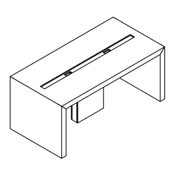
- Page 43 custom wood Installation Guides Section: TABLES Date: Sep 2019 Page No: 1 of 10 Description: CONFERENCE TABLE TCW_101 Rev. No: 0 Flat Edge (CWTF), Knife Edge (CWTK), Flat Wood-Metal, Edge USB (CWTM) and Extended Knife, Edge Power Conference Table (CWTP) NOTE : Flat Edge (CWTF) used for reference Width 96"...
- Page 44 custom wood Installation Guides Section: TABLES Date: Sep 2019 Page No: 2 of 10 Description: CONFERENCE TABLE TCW_101 Rev. No: 0 Part and Product Identification D - Extended Knife, A - Flat Edge Edge Power Width 96" to 108" I - 1/4-20x5/8" Cross/Sq. Comb, Width 96"...
- Page 45 custom wood Installation Guides Section: TABLES Date: Sep 2019 Page No: 3 of 10 Description: CONFERENCE TABLE TCW_101 INSTALL LEGS FASTEN LEG AND FRAME ASSEMBLY NOTE : For width 96" to 108" only NOTE : For width 96" to 108" only STEP 1a: Flip the Frame Assembly upside down and install the Legs as shown STEP 2a: Fasten the Legs and Frame Assembly using the screws provided...
- Page 46 custom wood Installation Guides Section: TABLES Date: Sep 2019 Page No: 4 of 10 Description: CONFERENCE TABLE TCW_101 INSTALL WORKSURFACE FASTEN FRAME AND WORKSURFACE NOTE : For width 96" to 108" only NOTE : For width 96" to 108" only STEP 3a: Flip the assembled structure upside down and place down the Worksurface STEP 4a: Fasten the Frame and Worksurface using the screws and brackets provided...
- Page 47 custom wood Installation Guides Section: TABLES Date: Sep 2019 Page No: 5 of 10 Description: CONFERENCE TABLE TCW_101 INSTALL LEGS FASTEN LEG AND FRAME ASSEMBLY NOTE : For width 120" to 240" NOTE : For width 120" to 240" STEP 1b: Flip the Frame Assembly upside down and install the Legs as shown STEP 2b: Fasten the Legs and Frame Assembly using the screws provided...
- Page 48 custom wood Installation Guides Section: TABLES Date: Sep 2019 Page No: 6 of 10 Description: CONFERENCE TABLE TCW_101 PLACING FASTEN THE BRACKET AND RAIL NOTE : 300 mm Leg is self standing while NOTE : For width 120" to 240" 150 mm Legs will be needing a support to lean on NOTE : For width 120"...
- Page 49 custom wood Installation Guides Section: TABLES Date: Sep 2019 Page No: 7 of 10 Description: CONFERENCE TABLE TCW_101 INSTALL LEG AND FRAME ASSEMBLY FASTEN BRACKET AND RAIL NOTE : For width 120" to 240" NOTE : For width 120" to 240" STEP 6b: Install the other end Leg and Frame Assembly while holding the previous assembly STEP 7b: Fasten the Bracket and Rail using the screws provided from sides for support...
- Page 50 custom wood Installation Guides Section: TABLES Date: Sep 2019 Page No: 8 of 10 Description: CONFERENCE TABLE TCW_101 INSTALL LEG FASTEN LEG AND RAIL NOTE : For width 156" and above only NOTE : For width 156" and above, a Leg in the middle will be installed for support STEP 8b: Install a Leg in the middle by tilting the structure STEP 9b: Fasten the Leg and Rail using screws provided...
- Page 51 custom wood Installation Guides Section: TABLES Date: Sep 2019 Page No: 9 of 10 Description: CONFERENCE TABLE TCW_101 INSTALL WORKSURFACE FASTEN FRAME AND WORKSURFACE NOTE : For width 120" to 240" NOTE : For width 120" to 240" STEP 10b: Install the Worksurface by placing it on the Frame STEP 11b: Fasten the Frame and Worksurface using the screws and brackets provided...
- Page 52 custom wood Installation Guides Section: TABLES Date: Sep 2019 Page No: 10 of 10 Description: CONFERENCE TABLE TCW_101 INSTALL CABLE MANAGEMENT TILE INSERT CABLE MANAGEMENT TILE NOTE : The number of Cable Management Tiles will vary depending upon the total width. 36" will be on the ends while 48" tiles will be in the middle. NOTE : For width 120"...
- Page 53 custom wood Installation Guides Section: STORAGE (C+D) Date: Sept 2019 Page No: 1 of 3 Description: CREDENZAS TCW_201 Rev. No: 0 CREDENZA 0.5 TOP CLOSED CABINET (CWSC), DRAWER AND Part and Product Identification CLOSED CABINET (CWSD) A - Closed Cabinet (CWSC) x1 B - Drawer and Closed Cabinet (CWSD) x1...
- Page 54 custom wood Installation Guides Section: STORAGE (C+D) Date: Sept 2019 Page No: 2 of 3 Description: CREDENZAS TCW_201 PLACE CABINET SECTIONS PLACE CREDENZA TOP STEP 1: Place Cabinet Sentions as shown above. Make sure to level and align them. STEP 2: Place Credenza Top and align with Cabinets.
- Page 55 custom wood Installation Guides Section: STORAGE (C+D) Date: Sept 2019 Page No: 3 of 3 Description: CREDENZAS TCW_201 FASTEN SCREWS STEP 3: Using appropriate drill bit, fasten screws.
Need help?
Do you have a question about the Custom wood CWCT Series and is the answer not in the manual?
Questions and answers