Advertisement
Quick Links
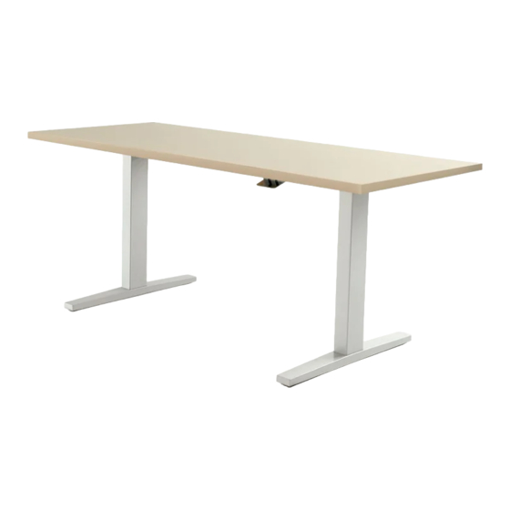
height-adjustable bench - Livello
INDEX
By Section
Product
Product Name
Code
INSTALLATION SUPPORT DOCUMENTS
Typical Installation Sequence
LIVELLO
FRAMES AND WORKSURFACE
Rectangular Worksurface
HABWRL
Livello Frame
HABFLV
Frame Link
HABFLF
System Link - HAB to Interpret
HABFLS1
SCREENS AND GABLES
Fixed Centre Screen - Glass
HABCFG
Fixed Centre Screen - Solid
HABCFS
Fixed Centre Screen - Fabric
HABCFF
Desk Edge Screen - Solid
HABCDS
Desk Edge Screen - 6 mm Glass
HABCDG
Desk Edge Screen - 10 mm Glass
HABCDG
Desk Edge Screen - Fabric
HABCDF
HAB End Gable-Metal
HABCGEML 203a
HAB Cable Channel
HABFCC
HAB Mid Gable-Metal
HABCGMML
HAB End Gable-Solid
HABCGESL 203b
HAB Cable Channel
HABFCC
HAB Mid Gable-Solid
HABCGMSL
End Cover - Metal
HABCCEML 203c
Mid Cover - Metal
HABCCMML
Study Carrel
GYKB
ELECTRICS
Power Harness
HABEPH
High Capacity Power Module
HABEPMH
Standard Power Module
HABEPMS
Receptacle Outlet
HABERO
I-Connector
HABEIC
Base Feed
HABEBF
Chicago Base Feed
HABEBFCH
Base Feed Cover
HABEBC
E-Chain
YEEC
Central Electrical Grommet Option
CEG1
Central Electrical Grommet Option
CEG2
Under Worksurface Mount w/ Cable
YEPD6A
Tray
January 2020
*Click on the desired Installation Guide to jump to the Guide
page.
Guide
Last
No.
Updated
Product Name
Ceiling Feed
Sep 2018
Chicago Ceiling Feed
Power Pole - End
Ceiling Feed
101
May 2017
Chicago Ceiling Feed
Power Pole - Mid
Power Conservation System
102
May 2017
201a
May 2017
201b
May 2017
201c
May 2017
202a
May 2017
202b
May 2017
202c
May 2017
202d
May 2017
May 2017
Aug 2017
May 2017
204
Sep 2019
301a
Jun 2017
301b
Jun 2017
301c
May 2017
301d
Jun 2017
Product
Guide
Last
Code
No.
Updated
Product Name
302a
Jan 2017
HABECF
HABECFCH
HABEPP
302b
Jun 2017
HABECF
HABECFCH
HABEPP
303
Jan 2018
HABEPC
Product
Guide
Last
Code
No.
Updated
PAGE 1 OF 1
Advertisement

Related Manuals for Teknion Livello


Summary of Contents for Teknion Livello
- Page 1 - Livello INDEX *Click on the desired Installation Guide to jump to the Guide By Section page. Product Guide Last Product Guide Last Product Guide Last Product Name Code Updated Product Name Code Updated Product Name Code Updated...
- Page 2 1 of 8 Description: STANDARD/EXTENDED RANGE FRAMES & WORKSURFACE HABL_101 Rev. No: 3 Livello Rectangular Worksurface (HABWRL), Livello Frame (HABFLV), Frame Link (HABFLF) NOTE: Frame Link is not included with the Frame. Must be ordered separately. For Customer Support please contact...
- Page 3 Rev. No: 3 Part and Product Identification B - Frame Link (HABFLF) x1 B2 - 1/4-20 X 5/8" Mach Screw, Quad, Truss A - Livello Rectangular Worksurface (HABWRL)x2 B1 - Frame Link (N09-5913) x2 (E01-1010) x8 C - Livello Frame (HABFLV) x1...
- Page 4 height-adjustable bench Installation Guides Section: FRAMES & WORKSURFACES Date: May 2017 Page No: 3 of 8 Description: STANDARD/EXTENDED RANGE FRAMES & WORKSURFACE HABL_101 INSTALL LEVELERS & ATTACH LEGS TO TOP CHANNEL Bracket NOTE: Make sure the circular cutouts on the Top Channel face the same side as the brackets welded on the Legs.
- Page 5 height-adjustable bench Installation Guides Section: FRAMES & WORKSURFACES Date: May 2017 Page No: 4 of 8 Description: STANDARD/EXTENDED RANGE FRAMES & WORKSURFACE HABL_101 ATTACH STRETCHER BAR TO LEGS STEP 2: Attach Stretcher Bars to Legs.
- Page 6 height-adjustable bench Installation Guides Section: FRAMES & WORKSURFACES Date: May 2017 Page No: 5 of 8 Description: STANDARD/EXTENDED RANGE FRAMES & WORKSURFACE HABL_101 ATTACH STRUTS TO LEGS STEP 3: Attach Struts to Legs.
- Page 7 height-adjustable bench Installation Guides Section: FRAMES & WORKSURFACES Date: May 2017 Page No: 6 of 8 Description: STANDARD/EXTENDED RANGE FRAMES & WORKSURFACE HABL_101 INSTALL FRAME LINK (NOT INCLUDED WITH FRAME - MUST ORDER SEPARATELY) NOTE: Level Both frames before attaching them to each other.
-
Page 8: Install Worksurfaces
STEP 5: Place Control Boxes inside of Top Channels & Connect Motor Cables , Switch and STEP 6: Bring Worksurfaces on top of Livello Frame. Align Worksurface & Strut holes. Fasten Power Cord with Control Boxes. Insert Power cord into Grommet & insert Grommet into worksurfaces in place with the 24 Pan Quad Machined Screws provided. - Page 9 height-adjustable bench Installation Guides Section: FRAMES & WORKSURFACES Date: May 2017 Page No: 8 of 8 Description: STANDARD/EXTENDED RANGE FRAMES & WORKSURFACE HABL_101 SECURE DISPLAY SWITCHES IN PLACE Bracket - Display Switch STEP 7: Insert Bracket into slot at the back of Display Switch until it snaps in place. Attach Display Switches to Worksurface as shown, with the four #10x3/4" Pan Quad Screws provided (two per Display Switch).
- Page 10 E - 1/4-20X3/4" Mach. Screw Quad Truss (E01-2010) x2 IMPORTANT: The System Link is not intended to provide structural support to the Interpret Frame. The System Link MUST ONLY be installed to Complete Interpret Frames with End Legs. For Customer Support please contact product.support@teknion.com...
- Page 11 height-adjustable bench Installation Guides Section: FRAMES & WORKSURFACE Date: May 2017 Page No: 2 of 4 Description: SYSTEM LINK - HEIGHT-ADJUSTABLE BENCH (HAB) TO INTERPRET HABL_102 ATTACH TOP BRACKET TO INTERPRET FRAME PLACE BOTTOM BRACKET IN PLACE Center Beam Interpret Frame NOTE : DO NOT fully tighten Nuts...
- Page 12 height-adjustable bench Installation Guides Section: FRAMES & WORKSURFACE Date: May 2017 Page No: 3 of 4 Description: SYSTEM LINK - HEIGHT-ADJUSTABLE BENCH (HAB) TO INTERPRET HABL_102 ATTACH BOTTOM BRACKET TO HAB FRAME TIGHTEN BRACKET NUTS Stretcher Bar - HAB Frame NOTE: Make sure to level both Frames before tightening the...
- Page 13 height-adjustable bench Installation Guides Section: FRAMES & WORKSURFACE Date: May 2017 Page No: 4 of 4 Description: SYSTEM LINK - HEIGHT-ADJUSTABLE BENCH (HAB) TO INTERPRET HABL_102 ROUTE CABLES THROUGH SYSTEM LINK INSTALL FRAME LINK COVER Connects to Interpret OPTIONAL Connects to HAB Underside View...
- Page 14 D6 -Set Screw Casual Screen 1/4-20 X1/4 (A25-0395) x1 Hex Socket NOTE: Fixed Center Black Flat Screen (HABCFG7251) Point shown as an example. (E01-0760) x3 D3 -Spacer, Wood D7 -Mounting Casual Screen (A25-0396) x2 (A25-0386) x1 For Customer Support please contact product.support@teknion.com...
-
Page 15: Front View
height-adjustable bench Installation Guides Section: SCREENS AND GABLES Date: May 2017 Page No: 2 of 7 Description: FIXED CENTER SCREEN - 10 mm GLASS HABL_201a INSERT CLAMP INTO CENTER RAIL CLAMP LOCATIONS Center FRONT VIEW Rail EQ=Equally Spaced NOTE: Make sure to USE ALL THE CLAMPS PROVIDED and space them as indicated on 3 Clamps - Length 48"... - Page 16 height-adjustable bench Installation Guides Section: SCREENS AND GABLES Date: May 2017 Page No: 3 of 7 Description: FIXED CENTER SCREEN - 10 mm GLASS HABL_201a LOCK CLAMPS STEP 2: Insert Springs into the the Clamps slots. Use Allen Key to rotate Mounting Nuts and lock Clamps into Center Rail.
-
Page 17: Install End Caps
height-adjustable bench Installation Guides Section: SCREENS AND GABLES Date: May 2017 Page No: 4 of 7 Description: FIXED CENTER SCREEN - 10 mm GLASS HABL_201a INSTALL END CAPS STEP 3: Insert both End Caps into Clamps. - Page 18 height-adjustable bench Installation Guides Section: SCREENS AND GABLES Date: May 2017 Page No: 5 of 7 Description: FIXED CENTER SCREEN - 10 mm GLASS HABL_201a INSERT RUBBER PADS AND GLASS SCREEN INSERT SPACERS Side View STEP 4: Insert Rubber pads and Glass Screen into Clamps, as shown. STEP 5: Insert spacers as shown, on one side first, in between Rubber Pads and Clamps.
- Page 19 height-adjustable bench Installation Guides Section: SCREENS AND GABLES Date: May 2017 Page No: 6 of 7 Description: FIXED CENTER SCREEN - 10 mm GLASS HABL_201a LOCK IN PLACE & LEVEL GLASS Opposite Side Secure Glass NOTE: Tighten Set Screws on both sides at the same time to make sure Glass is located in the center of Clamps.
- Page 20 height-adjustable bench Installation Guides Section: SCREENS AND GABLES Date: May 2017 Page No: 7 of 7 Description: FIXED CENTER SCREEN - 10 mm GLASS HABL_201a INSTALL BOTTOM COVERS Spring Clamp & Bottom Cover Section View STEP 7: Mount Bottom Covers on both sides of Clamps. NOTE: Make sure Covers click on the springs.
- Page 21 D5 -Set Screw 1/4-20 X1/4 Hex Socket D2 -Spacer, Wood Black Flat Point Casual Screen (E01-0760) x1 (A25-0396) x2 NOTE: Fixed Center Screen (HABCFS7251) D6 -Mounting Nut shown as an example. (A25-0386) x1 D3 -Spring (A09-0032) x2 For Customer Support please contact product.support@teknion.com...
-
Page 22: Side View
height-adjustable bench Installation Guides Section: SCREENS AND GABLES Date: May 2017 Page No: 2 of 7 Description: FIXED CENTER SCREEN - SOLID HABL_201b INSERT CLAMP INTO CENTER RAIL CLAMP LOCATIONS Center SIDE VIEW NOTE: Make sure to USE ALL Rail THE CLAMPS PROVIDED and space them as indicated on these drawings. - Page 23 height-adjustable bench Installation Guides Section: SCREENS AND GABLES Date: May 2017 Page No: 3 of 7 Description: FIXED CENTER SCREEN - SOLID HABL_201b LOCK CLAMPS STEP 2: Insert Springs into the the Clamps slots. Use Allen Key to rotate Mounting Nuts and lock Clamps into Center Rail.
- Page 24 height-adjustable bench Installation Guides Section: SCREENS AND GABLES Date: May 2017 Page No: 4 of 7 Description: FIXED CENTER SCREEN - SOLID HABL_201b INSTALL END CAPS Spring STEP 3: Insert both End Caps into Clamps.
-
Page 25: Cross Section View
height-adjustable bench Installation Guides Section: SCREENS AND GABLES Date: May 2017 Page No: 5 of 7 Description: FIXED CENTER SCREEN - SOLID HABL_201b INSERT SPACERS INTO ONE SIDE AND SOLID SCREEN INTO CLAMPS DETAIL CROSS SECTION VIEW STEP 4: Insert Spacers into Clamps on the side with one hole for set of screws. Insert Screen panel into Clamps. NOTE: Make sure to insert spacers into one side of clamps only. - Page 26 height-adjustable bench Installation Guides Section: SCREENS AND GABLES Date: May 2017 Page No: 6 of 7 Description: FIXED CENTER SCREEN - SOLID HABL_201b INSERT REMAINING SPACERS SECURE SCREEN IN PLACE Secure Screen STEP 5: Insert remaining spacers into the clamp side with two holes for set of screws. STEP 6: Tighten Set Screws to secure Solid Screen in place.
- Page 27 height-adjustable bench Installation Guides Section: SCREENS AND GABLES Date: May 2017 Page No: 7 of 7 Description: FIXED CENTER SCREEN - SOLID HABL_201b INSTALL BOTTOM COVERS Spring Clamp & Bottom Cover Section View STEP 7: Mount Bottom Covers on both sides of Clamps. NOTE: Make sure Covers click on the springs.
- Page 28 (A18-0251) x2 A1b - Mounting Nut (A25-0386) x2 A1c - Support Bracket - Fabric Screen (A16-3499) x2 A1d - Bushing - Fabric Screen (B02-0469) x2 A1e - #8x0.75" Quadrex Flat Head Screw For Customer Support please contact (E01-0947) x4 product.support@teknion.com...
- Page 29 height-adjustable bench Installation Guides Section: SCREENS AND GABLES Date: May 2017 Page No: 2 of 5 Description: FIXED CENTER SCREEN - FABRIC HABL_201c SUPPORT BRACKET ASSEMBLY ATTACH SUPPORT BRACKETS STEP 1: Attach Mounting Pin, Support Bracket and Bushing as shown. INSERT ALLEN KEY Detail View STEP 2: Insert Allen Key through the hole on Mounting Pin.
- Page 30 height-adjustable bench Installation Guides Section: SCREENS AND GABLES Date: May 2017 Page No: 3 of 5 Description: FIXED CENTER SCREEN - FABRIC HABL_201c ATTACH SCREEN TIGHTEN MOUNTING NUTS Top View Top View STEP 4: Rotate Mounting Nuts parallel with the Center Rail Channel, then attach Fabric Screen STEP 5: Rotate Allen Key to tighten Mounting Nuts and make sure it positioned as shown in into the Center Rail Channel.
- Page 31 height-adjustable bench Installation Guides Section: SCREENS AND GABLES Date: May 2017 Page No: 4 of 5 Description: FIXED CENTER SCREEN - FABRIC HABL_201c REMOVE ALLEN KEYS Detail View STEP 6: Remove Allen Keys.
- Page 32 height-adjustable bench Installation Guides Section: SCREENS AND GABLES Date: May 2017 Page No: 5 of 5 Description: FIXED CENTER SCREEN - FABRIC HABL_201c PRESS SCREEN SECURE SCREEN Detail View STEP 7: Press Fabric Screen down and make sure Screen Frame secured with Bushing. STEP 8: Fasten Support Brackets with Fabric Screen with Screws provided.
- Page 33 1/4-20x1-1/8" Long, Flat, Quadrex, Zinc (E01-0906) 48"-54" x3 60"-66" x4 72"-96" x5 B4 - #10x1", Pan, Quadrex Wood Screw, Deep Thread, Zink (E07-0097) 48" x10 54"-60" x14 For Customer Support please contact 66"-72" x18 product.support@teknion.com 78"-84" x22 90" x26 96" x30...
- Page 34 height-adjustable bench Installation Guides Section: SCREENS AND GABLES Date: May 2017 Page No: 2 of 3 Description: DESK EDGE SCREEN - SOLID HABL_202a SCREEN MOUNTING KIT ASSEMBLY MARK CENTERLINE Underside View STEP 1: Fasten Screen Bar-Subassembly and Mounting Bracket to the Solid Screen. STEP 2: Mark the center on the bottom of the Worksurface with pencil as shown.
- Page 35 height-adjustable bench Installation Guides Section: SCREENS AND GABLES Date: May 2017 Page No: 3 of 3 Description: DESK EDGE SCREEN - SOLID HABL_202a ATTACH & ALIGN SCREEN SECURE SCREEN Underside View Detail View Underside View Detail View STEP 3: Attach Mounting Bracket to the back of the Worksurface. Make sure the cut out of the STEP 4: Fasten Mounting Bracket to the underside of the Worksurface as shown.
- Page 36 72"-96" x5 B4 - 1/4-20x3/4" Machine Screw, Flat (E01-0484) 48"-54" x3 60"-66" x4 72"-96" x5 B5 - #10x1", Pan, Quadrex Wood Screw, Deep Thread, Zink For Customer Support please contact (E07-0097) 48" x10 product.support@teknion.com 54"-60" x14 66"-72" x18 78"-84" x22...
- Page 37 height-adjustable bench Installation Guides Section: SCREENS AND GABLES Date: May 2017 Page No: 2 of 3 Description: DESK EDGE SCREEN - 6mm GLASS HABL_202b SCREEN MOUNTING KIT ASSEMBLY MARK CENTERLINE Underside View STEP 1: Fasten Screen Bar-Subassembly and Mounting Bracket to the 6mm Glass Screen. STEP 2: Mark Centerline at the bottom of the Worksurface with pencil as shown.
- Page 38 height-adjustable bench Installation Guides Section: SCREENS AND GABLES Date: May 2017 Page No: 3 of 3 Description: DESK EDGE SCREEN - 6mm GLASS HABL_202b ATTACH & ALIGN SCREEN SECURE SCREEN Underside View Detail View Detail View Underside View STEP 3: Attach Mounting Bracket to the back of the Worksurface. Make sure the cut out of the STEP 4: Fasten Mounting Bracket to the underside of the Worksurface as shown.
- Page 39 72"-96" x5 B4 - 1/4-20x3/4" Machine Screw, Flat (E03-0723) 48"-54" x3 60"-66" x4 72"-96" x5 B5 - #10x1", Pan, Quadrex Wood Screw, Deep Thread, Zink For Customer Support please contact (E07-0097) 48" x10 product.support@teknion.com 54"-60" x14 66"-72" x18 78"-84" x22...
- Page 40 height-adjustable bench Installation Guides Section: SCREENS AND GABLES Date: May 2017 Page No: 2 of 3 Description: DESK EDGE SCREEN - 10mm GLASS HABL_202c SCREEN MOUNTING KIT ASSEMBLY MARK CENTERLINE Underside View STEP 1: Fasten Screen Bar-Subassembly and Mounting Bracket to the 6mm Glass Screen. STEP 2: Mark the center on the bottom of the Worksurface with pencil as shown.
- Page 41 height-adjustable bench Installation Guides Section: SCREENS AND GABLES Date: May 2017 Page No: 3 of 3 Description: DESK EDGE SCREEN - 10mm GLASS HABL_202c ATTACH & ALIGN SCREEN SECURE SCREEN Underside View Detail View Detail View Underside View STEP 3: Attach Mounting Bracket to the back of the Worksurface. Make sure the cut out of the STEP 4: Fasten Mounting Bracket to the underside of the Worksurface as shown.
- Page 42 height-adjustable bench Installation Guides Section: SCREENS AND GABLES Date: May 2018 Page No: 1 of 5 Description: DESK EDGE SCREEN - FABRIC HABL_202d Rev. No: 4 Desk Edge Screen - Fabric (HABCDF) Part and Product Identification A - Fabric Desk Edge Screen Sub-assembly (N09-5049) x1 B1 - Desk Edge Screen...
- Page 43 height-adjustable bench Installation Guides Section: SCREENS AND GABLES Date: May 2018 Page No: 2 of 5 Description: DESK EDGE SCREEN - FABRIC HABL_202d SCREEN MOUNTING KIT ASSEMBLY INSERT WASHER & TIGHTEN BRACKET Side View STEP 1: Fasten Screen Bar-Subassembly and Mounting Bracket to the Solid Screen loosely. STEP 2: Insert Slotted Washers to Screws between Bracket and Fabric Frame.
- Page 44 height-adjustable bench Installation Guides Section: SCREENS AND GABLES Date: May 2018 Page No: 3 of 5 Description: DESK EDGE SCREEN - FABRIC HABL_202d MARK CENTER ATTACH & ALIGN SCREEN Underside View Detail View Underside View STEP 3: Mark the center on the bottom of Worksurface with pencil. STEP 4: Attach Mounting Bracket to the back of the Worksurface.
- Page 45 height-adjustable bench Installation Guides Section: SCREENS AND GABLES Date: May 2018 Page No: 4 of 5 Description: DESK EDGE SCREEN - FABRIC HABL_202d SECURE SCREEN Underside View Detail View STEP 5: Fasten Mounting Bracket to the underside of the Worksurface as shown. NOTE: Fasten Screws to outer pilot holes.
- Page 46 height-adjustable bench Installation Guides Section: SCREENS & GUIDES Date: May 2018 Page No: 5 of 5 Description: DESK EDGE SCREEN - FABRIC HABL_202d ATTACH SHIMS (OPTIONAL) ATTACH SHIMS (OPTIONAL) NOTE: Only applicable if the Screen is leaning NOTE: Only applicable if the Screen is leaning towards the Desk after mounting.
- Page 47 (N09-5185) x2 & Top Cover for Metal Mid or (N09-5186) x2 Gable w/Power Pole (A16-3086) x1 C2 - Front Cover Assembly Mid Gable C4b - Top Cover for Metal Mid For Customer Support please contact (N09-5182) x2 Gable (A16-3025) x2 product.support@teknion.com...
- Page 48 height-adjustable bench Installation Guides Section: SCREENS AND GABLES Date: May 2017 Page No: 2 of 16 Description: METAL GABLES & CABLE CHANNEL HABL_203a REMOVE SUPPORT BRACKETS & COMMUNICATION PLATE COVER STEP 1: Remove Support Brackets and Communication Plate Cover as shown.
- Page 49 height-adjustable bench Installation Guides Section: SCREENS AND GABLES Date: May 2017 Page No: 3 of 16 Description: METAL GABLES & CABLE CHANNEL HABL_203a APPLY FOAM RUBBERS ATTACH SUPPORT BRACKET STEP 2: Attach Foam Rubbers onto the center of the Table Legs' inner side. STEP 3: Insert Support Bracket through the cut-out on the Inside Cover Assembly as shown.
- Page 50 height-adjustable bench Installation Guides Section: SCREENS AND GABLES Date: May 2017 Page No: 4 of 16 Description: METAL GABLES & CABLE CHANNEL HABL_203a LOOSEN LEGS HEX BOLT MOUNT INSIDE COVER Leveler Leg Hex Bolt STEP 4: Loosen Legs Hex Bolt to allow enough room for Gable Connecting Plate. Strretcher Bar ATTACH CONNECTING PLATES TO FRAME LEGS STEP 5: Fasten Gable Connecting Plates to Frame Legs.
- Page 51 height-adjustable bench Installation Guides Section: SCREENS AND GABLES Date: May 2017 Page No: 5 of 16 Description: METAL GABLES & CABLE CHANNEL HABL_203a FASTEN INSIDE COVER IN PLACE SECURE INSIDE COVER ASSEMBLY TO FRAME Opposite Side STEP 7: Make sure the face of the Inside Cover Assembly is flush with the Leg. Secure Inside STEP 8: Secure Inside Cover Assembly to Stretcher Bar with Bolts.
- Page 52 height-adjustable bench Installation Guides Section: SCREENS AND GABLES Date: May 2017 Page No: 6 of 16 Description: METAL GABLES & CABLE CHANNEL HABL_203a MOUNT OUTSIDE COVER ASSEMBLY Opposite Side STEP 9: Mount Outside Cover Assembly to the highlighted part of the Inside Cover Assembly as shown. STEP 9: Mount Outside Cover Assembly to the highlighted part of the Inside Cover Assembly as shown.
- Page 53 height-adjustable bench Installation Guides Section: SCREENS AND GABLES Date: May 2017 Page No: 7 of 16 Description: METAL GABLES & CABLE CHANNEL HABL_203a MID POWER POLE SUPPORT PLATE (OPTIONAL) ATTACH SUPPORT BRACKET NOTE: Please refer to installation guide HABL_302b for detail. Connecting Bracket Hex Bolt 5/16-18x1"...
- Page 54 height-adjustable bench Installation Guides Section: SCREENS AND GABLES Date: May 2017 Page No: 8 of 16 Description: METAL GABLES & CABLE CHANNEL HABL_203a SCREENS AND GABLES SECURE SIDE COVER ASSEMBLY NOTE: Please refer to Specification Drawing to mount the correct Side Cover Assembly.
- Page 55 height-adjustable bench Installation Guides Section: SCREENS AND GABLES Date: May 2017 Page No: 9 of 16 Description: METAL GABLES & CABLE CHANNEL HABL_203a CABLE CHANNEL ASSEMBLY Power Module Cover Standard Power Module E-Chain High Capacity Power Module Base Feed NOTE: Install Cable Channel Cover Plate(B9) on Cable Channel where E-Chain is not specified or unused location.
- Page 56 height-adjustable bench Installation Guides Section: SCREENS AND GABLES Date: May 2017 Page No: 10 of 16 Description: METAL GABLES & CABLE CHANNEL HABL_203a ATTACH CABLE CHANNEL & CENTER RAIL SECURE CABLE CHANNEL Underside View STEP 13: Align holes on Support Brackets, Cable Channel Assembly. Insert Bolts inside Center STEP 14: Secure Cable Channel in place with Nuts.
- Page 57 height-adjustable bench Installation Guides Section: SCREENS AND GABLES Date: May 2017 Page No: 11 of 16 Description: METAL GABLES & CABLE CHANNEL HABL_203a ATTACH SUPPORT BRACKET MOUNT SIDE COVER ASSEMBLY STEP 15: Insert Support Bracket through the cut-out on the Side Cover Assembly. STEP 16: Mount Side Cover Assembly onto the Stretcher Bar as shown.
- Page 58 height-adjustable bench Installation Guides Section: SCREENS AND GABLES Date: May 2017 Page No: 12 of 16 Description: METAL GABLES & CABLE CHANNEL HABL_203a SECURE SIDE COVER ASSEMBLY ATTACH MAGNET NOTE: Attach Magnets approximately to the locations to the Legs. STEP 17: Secure Side Cover Assembly with Stretcher Bar with Bolts. STEP 18: Attach Magnets to the inside of the Front Covers as shown.
- Page 59 height-adjustable bench Installation Guides Section: SCREENS AND GABLES Date: May 2017 Page No: 13 of 16 Description: METAL GABLES & CABLE CHANNEL HABL_203a MOUNT FRONT COVER ASSEMBLIES Opposite Side Detail View Detail View NOTE: Make sure Magnets are attached to the Legs. STEP 19: Mount Front Covers onto the Side Covers as shown in Detail View.
- Page 60 height-adjustable bench Installation Guides Section: SCREENS AND GABLES Date: May 2017 Page No: 14 of 16 Description: METAL GABLES & CABLE CHANNEL HABL_203a CABLE CHANNEL ASSEMBLY ATTACH TOP COVER Underside View STEP 20: Align holes on Support Brackets, Cable Channel Assembly. Insert Bolts inside Center STEP 21: Attach Top Covers onto the highlighted extrusions on the Side and Front Cover Rail Extrusion through Cable Channel Assembly and Brackets as shown.
- Page 61 height-adjustable bench Installation Guides Section: SCREENS AND GABLES Date: May 2017 Page No: 15 of 16 Description: METAL GABLES & CABLE CHANNEL HABL_203a TOP COVER w/POWER POLE CUTOUT (OPTIONAL) STEP 22: If Mid Gable Power Pole is specified. Attach Top Covers onto the highlighted extrusions on the Side and Front Cover Assemblies as shown. Repeat Step 1-14 to install End Gable and Cable Channel on another side of the Table.
- Page 62 height-adjustable bench Installation Guides Section: SCREENS AND GABLES Date: May 2017 Page No: 16 of 16 Description: METAL GABLES & CABLE CHANNEL HABL_203a CENTER RAIL EXTRUSION CAP STEP 23: Insert Center Rail Extrusion Caps onto Center Rail Extrusions as shown.
- Page 63 height-adjustable bench Installation Guides Section: SCREENS AND GABLES Date: Aug 2017 Page No: 1 of 16 Description: SOLID GABLES & CABLE CHANNEL HABL_203b Rev. No: 06 HAB End Gable-Solid (HABCGESL), HAB Cable Part and Product Identification Channel (HABFCC) & HAB Mid Gable-Solid (HABCGMSL) A1 - Inside Cover Assembly A2 - Cover for End Gable for Wood End Gable...
- Page 64 height-adjustable bench Installation Guides Section: SCREENS AND GABLES Date: Aug 2017 Page No: 2 of 16 Description: SOLID GABLES & CABLE CHANNEL HABL_203b REMOVE SUPPORT BRACKETS AND COMMUNICATION PLATE COVER STEP 1: Remove Support Brackets and Communication Plate Cover as shown.
- Page 65 height-adjustable bench Installation Guides Section: SCREENS AND GABLES Date: Aug 2017 Page No: 3 of 16 Description: SOLID GABLES & CABLE CHANNEL HABL_203b ATTACH SUPPORT BRACKET APPLY FOAM RUBBERS STEP 2: Fasten Brackets to Outside Cover Assembly. STEP 3: Insert Support Bracket through the cut-out on the Inside Cover Assembly as shown.
- Page 66 height-adjustable bench Installation Guides Section: SCREENS AND GABLES Date: Aug 2017 Page No: 4 of 16 Description: SOLID GABLES & CABLE CHANNEL HABL_203b ATTACH CONNECTION PLATES TO FRAME LEGS Leveler Leg Hex Bolt Please refer to Installation Guide No. HABL_101a for information.
- Page 67 height-adjustable bench Installation Guides Section: SCREENS AND GABLES Date: Aug 2017 Page No: 5 of 16 Description: SOLID GABLES & CABLE CHANNEL HABL_203b MOUNT INSIDE COVER ASSEMBLY Section View STEP 5: Mount Inside Cover Assembly onto Stretcher Bar. Make sure the face of the Inside Cover Assembly is flush with the Leg as shown in Section View. Secure Inside Cover Assembly to Gable Connecting Plate on both sides using Tap Quad Pan screws provided.
- Page 68 height-adjustable bench Installation Guides Section: SCREENS AND GABLES Date: Aug 2017 Page No: 6 of 16 Description: SOLID GABLES & CABLE CHANNEL HABL_203b SECURE TO THE STRETCHER BAR Opposite Side STEP 6: Secure Inside Cover Assembly to Stretcher Bar with Bolts.
- Page 69 height-adjustable bench Installation Guides Section: SCREENS AND GABLES Date: Aug 2017 Page No: 7 of 16 Description: SOLID GABLES & CABLE CHANNEL HABL_203b MOUNT OUTSIDE COVER ASSEMBLY Section View Section View STEP 7: Mount Outside Cover Assembly to the highlighted part of the Inside Cover Assembly as shown.
- Page 70 height-adjustable bench Installation Guides Section: SCREENS AND GABLES Date: Aug 2017 Page No: 8 of 16 Description: SOLID GABLES & CABLE CHANNEL HABL_203b ATTACH CONNECTING PLATES TO FRAME LEGS Leveler Leg Hex Bolt STEP 8: Loosen Legs Hex Bolt to allow enough room for Gable Connecting Plate. Fasten Gable Connecting Plates to Frame Legs.
- Page 71 height-adjustable bench Installation Guides Section: SCREENS AND GABLES Date: Aug 2017 Page No: 9 of 16 Description: SOLID GABLES & CABLE CHANNEL HABL_203b MOUNT BOTTOM ANGLE BAR STEP 9: Mount Bottom Angle Bar and secure to Gable Connecting Plate on both sides using Tap Quad Pan screws provided.
- Page 72 height-adjustable bench Installation Guides Section: SCREENS AND GABLES Date: Aug 2017 Page No: 10 of 16 Description: SOLID GABLES & CABLE CHANNEL HABL_203b MID POWER POLE SUPPORT PLATE ATTACH SUPPORT BRACKET NOTE: Please refer to installation guide HABL_302b for detail. Connecting Bracket Hex Bolt 5/16-18x1"...
- Page 73 height-adjustable bench Installation Guides Section: SCREENS AND GABLES Date: Aug 2017 Page No: 11 of 16 Description: SOLID GABLES & CABLE CHANNEL HABL_203b MOUNT SIDE COVER ASSEMBLY SECURE SIDE COVER ASSEMBLY NOTE: Side Cover with Base Feed Cut-out shown as an example. NOTE: Please refer to Specification Drawing to mount the correct Side...
-
Page 74: Cable Chain Assembly
height-adjustable bench Installation Guides Section: SCREENS AND GABLES Date: Aug 2017 Page No: 12 of 16 Description: SOLID GABLES & CABLE CHANNEL HABL_203b CABLE CHAIN ASSEMBLY E-Chain NOTE: Electrics components have to Power Module installed on Cable Channel Cover before connecting to Support Bracket. - Page 75 height-adjustable bench Installation Guides Section: SCREENS AND GABLES Date: Aug 2017 Page No: 13 of 16 Description: SOLID GABLES & CABLE CHANNEL HABL_203b CABLE CHANNEL ASSEMBLY AND CENTER RAIL SECURE CABLE CHANNEL NOTE: Please repeat STEP 1 to 14 if second Cable Channel is specified .
- Page 76 height-adjustable bench Installation Guides Section: SCREENS AND GABLES Date: Aug 2017 Page No: 14 of 16 Description: SOLID GABLES & CABLE CHANNEL HABL_203b MOUNT FRONT COVER ASSEMBLIES Section View STEP 15: Mount Front Covers onto the Frame Link and Bottom Connecting Brackets.
- Page 77 height-adjustable bench Installation Guides Section: SCREENS AND GABLES Date: Aug 2017 Page No: 15 of 16 Description: SOLID GABLES & CABLE CHANNEL HABL_203b TOP COVER W/ POWER POLE CUTOUT (OPTIONAL) STEP 16a: If Mid Gable Power Pole is specified. Attach Top Covers onto the highlighted extrusions on the Side and Front Cover Assemblies as shown. Repeat Step 1-14 to install End Gable and Cable Channel on another side of the Table.
- Page 78 height-adjustable bench Installation Guides Section: SCREENS AND GABLES Date: Aug 2017 Page No: 16 of 16 Description: SOLID GABLES & CABLE CHANNEL HABL_203b ATTACH TOP COVER CENTER RAIL EXTRUSION CAP STEP 16b: STEP 17: Rest Top Covers onto Gable structures as shown. Insert Center Rail Extrusion Caps onto Center Rail Extrusions as shown.
- Page 79 NOTE: Mid Cover with Cable Cutout shown as an example. For Cable Channel installation procedures, please refer to guide For Customer Support please contact For Customer Support please contact For Customer Support please contact HABL_203a or 203b product.support@teknion.com product.support@teknion.com product.support@teknion.com...
- Page 80 height-adjustable bench Installation Guides Section: SCREENS & GABLES Date: May 2017 Page No: 2 of 3 Description: MID & END COVER - METAL HABL_203c SLIDE SUPPORT BRACKET INTO END COVER SECURE END COVER IN PLACE Support Bracket - Ships with Cable Channel NOTE: End Cover with Cable Cutout shown as an example.
- Page 81 height-adjustable bench Installation Guides Section: SCREENS & GABLES Date: May 2017 Page No: 3 of 3 Description: MID & END COVER - METAL HABL_203c INSTALL METAL MID COVER NOTE: Mid Cover with Cable Cutout shown as an example. For Cable Channel installation procedures, please refer to guide HABL_203...
- Page 82 height-adjustable bench Installation Guides Section: STUDY CARREL Date: Sept 2019 Page No: 1 of 4 Description: STUDY CARREL INSTALLATION HABL_204 Rev. No: 1 Study Carrel (GYKB) Part and Product Identification A - Screen Mounting Pin (A18-0251) x4 B - #10 x 0.875" Lg. Screw (E07-0077) x4 C - Mounting Bracket (N09-8285) x2...
- Page 83 height-adjustable bench Installation Guides Section: STUDY CARREL Date: Sept 2019 Page No: 2 of 4 Description: STUDY CARREL INSTALLATION HABL_204 SCREW MOUNTING PINS SLIDE BRACKET ONTO WORKSURFACE Worksurface STEP 1: Screw Screen Mounting Pin to Brackets STEP 2: Slide Brackets onto Worksurface...
- Page 84 height-adjustable bench Installation Guides Section: STUDY CARREL Date: Sept 2019 Page No: 3 of 4 Description: STUDY CARREL INSTALLATION HABL_204 ATTACH LONG EDGE SCREEN TO BRACKET REMOVE PLASTIC EXTRUSIONS Extrusions STEP 3: Slide Long Edge Screen onto Mounting Pins STEP 4: Remove plastic extrusions...
- Page 85 height-adjustable bench Installation Guides Section: STUDY CARREL Date: Sept 2019 Page No: 4 of 4 Description: STUDY CARREL INSTALLATION HABL_204 MOUNT AND ATTACH SIDE SCREENS SCREW BRACKET TO WORKSURFACE STEP 5: Slide Desk Edge Side Screen onto Mounting Pins and clip Desk Edge Side Screens STEP 6: Screw Bracket onto Worksurface into place to attach to Long Edge Screen...
- Page 86 Standard Power Module (HABEPMS), Chicago Power Module (HABEPMCH), Receptacle Outlet (HABERO), I-Connector (HABEIC) A1 - Standard Power Module (HABEPMS) x1 For Customer Support please contact product.support@teknion.com B1 - Power Module Covers (MPA15-E784) x1 C1 - 8 x 1/2" RND, ROB, Zinc type B (FS8 x 1.2-RRB) x11...
- Page 87 height-adjustable bench Section: Date: Jun 2017 Page No: 2 of 9 Description: HABL_301a HIGH CAPACITY POWER MODULE ASSEMBLY STEP 1a: Place the Receptacle against the STEP 3a: Fasten with Screws. Power Module. DETAIL STEP 2a: Slide to left to engage or right for STEP 4a: Fasten Bracket as Shown.
- Page 88 height-adjustable bench Section: Date: Jun 2017 Page No: 3 of 9 Description: HABL_301a STANDARD POWER MODULE ASSEMBLY STEP 1b: Place the Receptacle against the STEP 3b: Fasten with Screws. Power Module. DETAIL STEP 2b: Slide to left to engage or right for STEP 4b: Fasten Bracket as Shown.
- Page 89 height-adjustable bench Section: Date: Jun 2017 Page No: 4 of 9 Description: HABL_301a HIGH CAPACITY POWER MODULE ASSEMBLY Base Feed Power Module STEP 5a: Fasten Power Module assembly to underside of Cable Tray. Make sure to lineup holes of Cable tray to holes of Brackets.
- Page 90 height-adjustable bench Section: Date: Jun 2017 Page No: 5 of 9 Description: HABL_301a STANDARD POWER MODULE ASSEMBLY IMPORTANT: Fasten Standard Power Module ONLY in this orientation and at the location shown. Base Feed Location STEP 5b: Fasten Power Module assembly to underside of Cable Tray. Make sure to lineup holes of Cable tray to holes of Brackets.
- Page 91 height-adjustable bench Section: Date: Jun 2017 Page No: 6 of 9 Description: HABL_301a CHICAGO POWER MODULE ASSEMBLY NOTE: Licensed Electrician to install Chicago Base Feed. IMPORTANT: Fasten Chicago Power Module ONLY in this orientation and at the location shown. Base Feed Location STEP 5c: Fasten Chicago Power Module assembly to underside of Cable Tray.
- Page 92 height-adjustable bench Section: Date: Jun 2017 Page No: 7 of 9 Description: HABL_301a INSTALL POWER MODULE COVERS Tabs Follow same procedure when Power Modules are not shown installing covers to Standard in Cable Tray for clarification Power Module. only. STEP 6: Install Cover by inserting tabs of Cover inside cutouts of Cable Channel and fasten with screws. Make sure to lineup holes of cover with holes located under the Cable Tray.
-
Page 93: Power Harness
height-adjustable bench Section: Date: Jun 2017 Page No: 8 of 9 Description: HABL_301a POWER HARNESS Underside View Underside View STEP 7: Connect Power Harness to Power Module and I-Connector to Power Harness... - Page 94 height-adjustable bench Section: Date: Jun 2017 Page No: 9 of 9 Description: HABL_301a NOTE M-Clips Data Cover Wire Management Bracket Installers to determine the layout for the data, wire management bracket and m-clips in the hatched area.
- Page 95 height-adjustable bench Installation Guides Section: ELECTRICS Date: Jun 2017 Page No: 1 of 8 Description: BASE FEED, BASE FEED COVER AND MID BASE FEED HABL_301b Rev. No: 2 Base Feed End Condition (HABEBF), Split Base Feed (HABEBFS), Chicago Part and Product Identification Base Feed End Condition (HABEBFCH), Base Feed Cover (HABEBC), Base Feed Mid Condition (HABEBF__M) A1 - Base Feed...
- Page 96 height-adjustable bench Installation Guides Section: ELECTRICS Date: Jun 2017 Page No: 2 of 8 Description: BASE FEED, BASE FEED COVER AND MID BASE FEED HABL_301b INSTALL SPLIT BASE FEED INSTALL BOX COVER (OPTIONAL) Underside View STEP 1a: Install Split Base Feed. STEP 1b: Install Box Cover...
- Page 97 height-adjustable bench Installation Guides Section: ELECTRICS Date: Jun 2017 Page No: 3 of 8 Description: BASE FEED, BASE FEED COVER AND MID BASE FEED HABL_301b INSTALL BASE FEED INSTALL CABLE TRAY NOTE: Flip Cable Tray over and install to Frame. Cable Tray to be installed AFTER ALL Electrical components have been installed.
- Page 98 height-adjustable bench Installation Guides Section: ELECTRICS Date: Jun 2017 Page No: 4 of 8 Description: BASE FEED, BASE FEED COVER AND MID BASE FEED HABL_301b BRAKET TO STRETCHER BAR LOOSEN SCREW Stretcher Bar STEP 4: Fasten Bracket to underside of Stretcher Bar. STEP 5: Loosen screw to allow the cover bracket to adjust in height.
- Page 99 height-adjustable bench Installation Guides Section: ELECTRICS Date: Jun 2017 Page No: 5 of 8 Description: BASE FEED, BASE FEED COVER AND MID BASE FEED HABL_301b ADJUST COVER TIGHTEN SCREW Finish Floor STEP 6: Adjust Cover so it rest on Finish Floor. STEP 7: Tighten Screws.
- Page 100 height-adjustable bench Installation Guides Section: ELECTRICS Date: Jun 2017 Page No: 6 of 8 Description: BASE FEED, BASE FEED COVER AND MID BASE FEED HABL_301b INSERT CABLE INTO BASE FEED COVER Underside View STEP 8: Insert Base Feed Cable into Base Feed Cover as shown on illustration above.
- Page 101 height-adjustable bench Installation Guides Section: ELECTRICS Date: Jun 2017 Page No: 7 of 8 Description: BASE FEED, BASE FEED COVER AND MID BASE FEED HABL_301b INSTALL MID BASE FEED Underside View STEP 9: Fasten Middle bracket and Mid Base Feed. Install assembly to Stretcher Bars as shown.
- Page 102 height-adjustable bench Installation Guides Section: ELECTRICS Date: Jun 2017 Page No: 8 of 8 Description: BASE FEED, BASE FEED COVER AND MID BASE FEED HABL_301b NOTE M-Clips Data Cover Wire Management Bracket Installers to determine the layout for the data, wire management bracket and m-clips in the hatched area.
- Page 103 Robertson Screw (E01-1028) x2 C - WD Screw Pan Quad # 12 x 7/8" Black Oxide (E04-0087) x2 D - E-Chain Cable Tie (B02-0545) x1 E - LV Cable Manager Retainer For Customer Support please contact Clip product.support@teknion.com (A16-3890) x1...
- Page 104 height-adjustable bench Installation Guides Section: ELECTRICS Date: May 2017 Page No: 2 of 6 Description: E-CHAIN HABL_301c INSTALL BOTTOM LINK INSTALL REINFORCEMENT CLIP Cable Tray Underside View STEP 1: Fasten Bottom Link to underside of Cable Tray. Make sure to lineup holes of Cable STEP 2: Place the Reinforcement Clip on top of the Top Link and connect the E-Chain to the Tray to holes of the Bottom Link.
- Page 105 height-adjustable bench Installation Guides Section: ELECTRICS Date: May 2017 Page No: 3 of 6 Description: E-CHAIN HABL_301c INSTALL TOP LINK Pilot Holes Side View WorkSurface User Side Underside View Worksurface STEP 3: Install Top Link Assembly to the bottom of Worksurface. Make sure to align pilot holes to holes on top of the Top Link.
- Page 106 height-adjustable bench Installation Guides Section: ELECTRICS Date: May 2017 Page No: 4 of 6 Description: E-CHAIN HABL_301c ATTACHE E-CHAIN TO TOP AND BOTTOM LINKS cable Cable STEP 4: Push Cable into E-Chain. STEP 5: Attach E-chain to Top Link STEP 6: Secure cables with Cable Tie.
- Page 107 height-adjustable bench Installation Guides Section: ELECTRICS Date: May 2017 Page No: 5 of 6 Description: E-CHAIN HABL_301c NOTE Worksurface Make sure the E-Chain is installed straight. Side View...
- Page 108 height-adjustable bench Installation Guides Section: ELECTRICS Date: May 2017 Page No: 6 of 6 Description: E-CHAIN HABL_301c NOTE M-Clips Data Cover Wire Management Bracket Installers to determine the layout for the data, wire management bracket and m-clips in the hatched area.
- Page 109 HABL_301d Rev. No: 2 Central Electrical Grommet Option (CEG1 or CEG2), Cable Tray (YEPD6) Part and Product Identification For Customer Support please contact product.support@teknion.com A1 - Grommet Cover A2 - Power Tray B1 - Grommet Cover B2 - Power Tray C - #10 x 0.875"...
- Page 110 height-adjustable bench Section: Date: Jun 2017 Page No: 2 of 5 Description: HABL_301d INSERT GROMMET COVER IN WORKSURFACE PLACE POWER TRAY UNDER WORKSURFACE Underside View Worksurface NOTE: Make sure outlets and data are centered in opening of Grommet STEP 1: Insert Grommet Cover inside Worksurface Grommet. STEP 1: STEP 2: Place Power Tray to underside of worksurface STEP 2:...
- Page 111 height-adjustable bench Section: Date: Jun 2017 Page No: 3 of 5 Description: HABL_301d FASTEN TRAY NOTE: REFER TO INSTALLATION GUIDE NO. HABL_101 TO INSTALL WORKSURFACE TO FRAME. STEP 3: Fasten with wood screws.
- Page 112 height-adjustable bench Section: Date: Jun 2017 Page No: 4 of 5 Description: HABL_301d ATTACH CABLE TRAY NOTE: Installer to determine location to install Cable Tray. STEP 4: Fasten Cable Tray to underside of Worksurface.
- Page 113 height-adjustable bench Section: Date: Jun 2017 Page No: 5 of 5 Description: HABL_301d INSTALL POWER BAR STEP 5: Snap Power Bar in place as shown on illustration above.
- Page 122 (AEA21-0200-09) x1 M - Flat Washer (FW 0.25) x 8 N - Connecting Bracket (MPA15-E786) x 1 G - Power Pole Cover Base (AEA23-E014-10) x2 O - Hex Bolt 5/16-18x1" For Customer Support please contact Long ZP (E03-0641) x2 product.support@teknion.com...
- Page 123 height adjustable bench Installation Guides Section: ELECTRICS Date: Jun 2017 Page No: 2 of 8 Description: POWER POLE - MID & CEILING FEED HABL_302b CONNECTING BRACKET ASSEMBLY ATTACH LOWER EXTRUSION NOTE: Install Connection Bracket then proceed Underside View Mid-Gable installation. STEP 1: Install Connecting Bracket to the underside of the Stretch Bar.
- Page 124 height adjustable bench Installation Guides Section: ELECTRICS Date: Jun 2017 Page No: 3 of 8 Description: POWER POLE - MID & CEILING FEED HABL_302b SECURE BOTTOM EXTRUSION CEILING CUT OUT 3-1/2" 3-1/2" Power Pole length = distance + 3" STEP 3: Fasten Bracket to Lower Power Pole. STEP 4: Mark Power Pole position on the ceiling using Plum Bob Line.
- Page 125 height adjustable bench Installation Guides Section: ELECTRICS Date: Jun 2017 Page No: 4 of 8 Description: POWER POLE - MID & CEILING FEED HABL_302b UPPER EXTRUSION ASSEMBLY CEILING FEED ASSEMBLY STEP 5: Insert Upper power Pole Extrusion inside ceiling cut-out (uncut edge down). Drop STEP 6: Drop Ceiling Feed cable down through ceiling cut-out down along the Power Pole Power Pole Upper Extrusion on the top of Lower Extrusion and connect them together using Slide junction box bracket inside the Power Pole Extrusion.
-
Page 126: Cable Management
height adjustable bench Installation Guides Section: ELETRCIS Date: Jun 2017 Page No: 5 of 8 Description: POWER POLE - MID & CEILING FEED HABL_302b CABLE MANAGEMENT Cable Channel Mid Gable Top Cover STEP 6: Open Mid-Gable Top Cover and Connect Ceiling Feed and fish to the underside of the Cable Channel. - Page 127 height adjustable bench Installation Guides Section: ELECTRICS Date: Jun 2017 Page No: 6 of 8 Description: POWER POLE - MID & CEILING FEED HABL_302b ATTACH LOWER COVER ATTACH UPPER COVER Ceiling STEP 7: Tuck cable and attach Power Pole Covers by engaging them into Lower Extrusion. STEP 8: Insert Upper Covers inside ceiling cut-out then engage into Upper Power Pole Extrusion.
-
Page 128: Drill Holes
height adjustable bench Installation Guides Section: ELECTRICS Date: Jun 2017 Page No: 7 of 8 Description: POWER POLE - MID & CEILING FEED HABL_302b ATTACH CEILING PLATES DRILL HOLES WARNING: Do not connect to power source until installation is complete. All wire connections must be performed by a licensed electrician in accordance with applicable codes and regulations. - Page 129 height adjustable bench Installation Guides Section: ELECTRICS Date: Jun 2017 Page No: 8 of 8 Description: POWER POLE - MID & CEILING FEED HABL_302b PLATES INSTALLATION NOTE: Temporarily remove plates, in order to push T-nuts into pre-drilled holes,. Bring them back and fasten everything, as shown.
- Page 130 height adjustable bench Installation Guides Section: ELECTRICS Date: Jan 2018 Page No: 1 of 6 Description: POWER CONSERVATION SYSTEM INSTALLATION HABL_303 Rev. No: 0 Power Conservation System (HABEPC) Part and Product Identification A - #8 x 3/4 Slf Tping Scrw FS8x.075QPTEKS x4 B - Control Box Control Box-12.11 x1...
- Page 131 height adjustable bench Installation Guides Section: ELECTRICS Date: Jan 2018 Page No: 2 of 6 Description: POWER CONSERVATION INSTALLATION HABL_303 INSTALL POWER CONSERVATION SYSTEM CONNECT POWER CONSERVATION SYSTEM STEP 1: Install Power Conservation System beneath Cable Channel using Self Tapping Screws STEP 2: Connect Power Conservation System to Base Feed and Power Module...
- Page 132 height adjustable bench Installation Guides Section: ELECTRICS Date: Jan 2018 Page No: 3 of 6 Description: POWER CONSERVATION INSTALLATION HABL_303 MOUNT WORKSURFACES MOUNT SENSORS STEP 3: Mount Worksurfaces STEP 4: Mount Sensors using Wood Screws...
- Page 133 height adjustable bench Installation Guides Section: ELECTRICS Date: Jan 2018 Page No: 4 of 6 Description: POWER CONSERVATION SYSTEM INSTALLATION HABL_303 DESCRIPTION R 8.0' Note: Sensor placement will be based on location of User, Length of CAT3 Cable, and Desk Configuration...
- Page 134 height adjustable bench Installation Guides Section: ELECTRICS Date: Jan 2018 Page No: 5 of 6 Description: POWER CONSERVATION INSTALLATION HABL_303 CONNECT SENSOR TO POWER CONSERVATION SYSTEM Note: Press CAT3 Cable into Wire Manager STEP 5: Connect Sensor to Sensor using CAT3 Cable...
- Page 135 height adjustable bench Installation Guides Section: ELECTRICS Date: Jan 2018 Page No: 6 of 6 Description: POWER CONSERVATION INSTALLATION HABL_303 SENSOR GANGING STEP 6: Connect Sensors together using CAT3 Cable...
Need help?
Do you have a question about the Livello and is the answer not in the manual?
Questions and answers