
Related Manuals for SEW-Eurodrive MOVIPRO PHE Series


Summary of Contents for SEW-Eurodrive MOVIPRO PHE Series
- Page 1 *23576855_1017* Drive Technology \ Drive Automation \ System Integration \ Services Operating Instructions Drive and Application Controller ® MOVIPRO PHE..B-A15-.1X0..B-00 Edition 10/2017 23576855/EN...
- Page 2 SEW-EURODRIVE—Driving the world...
-
Page 3: Table Of Contents
Contents Contents General information........................ 7 About this documentation .................... 7 Other applicable documentation .................. 7 Structure of the safety notes ................... 7 1.3.1 Meaning of signal words ................ 7 1.3.2 Structure of section-related safety notes............ 7 1.3.3 Structure of embedded safety notes .............. 8 Rights to claim under limited warranty ................ 8 Exclusion of liability...................... 9 Product names and trademarks.................. 9... - Page 4 Contents Type designation...................... 23 Scope of delivery ...................... 23 Short designation ...................... 24 Nameplate........................ 24 Device overview...................... 25 Accessories........................ 25 4.6.1 Accessory components ................ 25 Mechanical installation ...................... 27 Requirements........................ 27 Mounting position...................... 28 Minimum clearance....................... 28 Cooling.......................... 29 Installation........................ 30 5.5.1 Fixed angle brackets .................. 31 5.5.2 Tapped holes on the rear of the device............ 31 Electrical installation......................
- Page 5 Contents 6.10.11 X5002_1: Digital inputs/outputs – communication and control unit.... 59 6.10.12 X5002_2: Digital input – communication and control unit ...... 59 6.10.13 X5002_3: Digital input – communication and control unit ...... 60 6.10.14 X5002_4: Digital input – communication and control unit ...... 60 6.10.15 X5003: Digital input –...
- Page 6 Contents 10.5 Safety-related characteristic value STO ............... 86 10.6 Dimension drawings...................... 87 ® 10.6.1 Device with motor connection HAN Q8/0 ........... 87 ® 10.6.2 Device with motor connection HAN 10E............. 89 10.6.3 Mounting bracket.................. 90 ® MAXOLUTION Competence Center .................. 91 Index ............................ 93 ®...
-
Page 7: General Information
General information About this documentation General information About this documentation The current version of the documentation is the original. This documentation is an integral part of the product. The documentation is written for all employees who assemble, install, start up, and service this product. Make sure this documentation is accessible and legible. -
Page 8: Structure Of Embedded Safety Notes
General information Rights to claim under limited warranty Meaning of the hazard symbols The hazard symbols in the safety notes have the following meaning: Hazard symbol Meaning General hazard Warning of dangerous electrical voltage Warning of hot surfaces Warning of risk of crushing Warning of suspended load Warning of automatic restart 1.3.3... -
Page 9: Exclusion Of Liability
General information Exclusion of liability Exclusion of liability Read the information in this documentation, otherwise safe operation is impossible. You must comply with the information contained in this documentation to achieve the specified product characteristics and performance features. SEW‑EURODRIVE as- sumes no liability for injury to persons or damage to equipment or property resulting from non-observance... -
Page 10: Safety Notes
Safety notes Preliminary information Safety notes Preliminary information The following general safety notes have the purpose to avoid injury and damage to property. They primarily apply to the use of products described in this documentation. If you use additional components also observe the relevant warning and safety notes. User duties As the user, you must ensure that the basic safety notes are observed and complied with. -
Page 11: Target Group
Safety notes Target group Target group Specialist for Any mechanical work may only be performed by adequately qualified specialists. Spe- mechanical work cialists in the context of this documentation are persons familiar with the design, mechanical installation, troubleshooting, and maintenance of the product who possess the following qualifications: •... -
Page 12: Designated Use
Safety notes Designated use Designated use The product is intended for installation in electrical plants or machines. In case of installation in electrical systems or machines, startup of the product is pro- hibited until it is determined that the machine meets the requirements stipulated in the local laws and directives. -
Page 13: Installation/Assembly
Safety notes Installation/assembly Installation/assembly Ensure that the product is installed and cooled according to the regulations in the doc- umentation. Protect the product from strong mechanical strain. The product and its mounting parts must never protrude into the path of persons or vehicles. Ensure that components are not deformed and insulation spaces are not changed, particularly during transportation and handling. -
Page 14: Protective Separation
Safety notes Protective separation Protective separation The product meets all requirements for protective separation of power and electronics connections in accordance with EN 61800-5-1. To ensure protective separation, all connected circuits must also meet the requirements for protective separation. 2.10 Startup/operation Do not deactivate monitoring and protection devices of the machine or system even for a test run. -
Page 15: Functional Safety
Functional safety Integrated safety technology Functional safety Integrated safety technology 3.1.1 Standards For the versions of the standards valid during development and testing of the device, refer to the declaration of conformity. 3.1.2 Safe state For safety-related operation of the device, safe torque off is defined as safe condi- tion. -
Page 16: Drive Safety Functions
Functional safety Integrated safety technology The following figure shows the safety concept: 21051507467 Safety relay, external Safety-related 24 V voltage supply Motor phase INFORMATION Observe chapter "Restrictions" (→ 2 18). 3.1.4 Drive safety functions STO – Safe Torque Off If the STO function is activated, the drive inverter no longer supplies power to the mo- tor. - Page 17 Functional safety Integrated safety technology INFORMATION The motor coasts to a halt or is stopped mechanically. Controlled standstill is preferred, if possible. SS1(c) – Safe Stop 1 When the SS1(c) function is active, the drive inverter brings the motor to a standstill electrically.
-
Page 18: Limitations
Functional safety Integrated safety technology 3.1.5 Limitations • The brake control integrated in this device and the standard brake integrated in brakemotors are not safety-related and therefore not part of the safety functions described in chapter "Drive safety functions". If the brake controller and/or the mo- tor brake fails, the drive can coast for much longer depending on the application (i.e. -
Page 19: Safety Requirements
Functional safety Safety requirements Safety requirements 3.2.1 Supports The safety functions of the device may only be used for safe operation of the system or machine if they are integrated correctly in an application-specific, higher-level safety function or safety system. We recommend that the system/machine manufacturer performs a risk assessment. -
Page 20: Requirements For The External Safety Controller
Functional safety Safety requirements • When planning the installation, observe the technical data of the device. • The IP 54 degree of protection must be preserved. This is only achieved if non- used connectors and covers are properly closed. 3.2.4 Requirements for the external safety controller A safety relay can be used as an alternative to a safety controller. -
Page 21: Startup Requirements
Functional safety Connection variants 3.2.5 Startup requirements • Startup of the system/machine must be documented. The safety functions of the system/machine must be checked and verified. Observe the limitations for the safety functions of the device provided in chapter "Limitations" (→ 2 18) when verifying safety functions. If necessary, deactivate non-safety-related parts and components, such as the motor brake, that affect the result of the verification. -
Page 22: Connection Of An External Safety Relay For Sto With M12 Plug Connector
Functional safety Connection variants It is mandatory to observe the information about the switching capacity according to EN 60947‑4‑1 and EN 60947‑5‑1 and the contact protection in the operating instruc- tions of the safety relay manufacturer. Compliance with this information is the sole re- sponsibility of the project planner. -
Page 23: Device Structure
Device structure Type designation Device structure Type designation The type designation contains the following data: ® MOVIPRO drive and application controller Motor connection: ® 1 = HAN Q8/0 ® 2 = HAN Signal interfaces: 1 = Communication package 1 2 = Communication package 2 3 = Communication package 3 (STO) basic Power supply: Three-phase current Maximum S1 device power: 1.5 kW Brake control: 2 = Control for 2-wire brakes... -
Page 24: Short Designation
Device structure Short designation Short designation The following short designations are used in this documentation: Component Short designation Drive and Application Controller Device ® MOVIPRO PHE..B-A15-.1X0..B-00 Nameplate The nameplate lists information about the device type. The following figure shows an example of a nameplate: Type: SO#:... -
Page 25: Device Overview
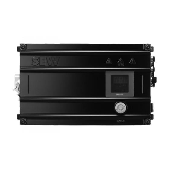
Device structure Device overview Device overview The following figure provides an example of an overview of the most important device components and the position of the labels on the device: 9007208588714251 Status and error codes label Status display and infrared interface Connection block (connections depend on the device design) Service interface PE connection... - Page 26 Device structure Accessories The following accessories are available depending on the device design. For further ® information, refer to the following documentation: “MOVIPRO Accessories” ad- dendum to operating instructions. If you are not sure which accessories you need, the SEW‑EURODRIVE staff will be glad to help you with your selection. Part number Keypad For further information, refer to the following documentation:...
-
Page 27: Mechanical Installation
Mechanical installation Requirements Mechanical installation Requirements WARNING Risk of crushing if the load falls. Severe or fatal injuries. • Do not stand under the load. • Secure the area where loads can fall down. NOTICE Risk of collision. Damage to plant and device components. •... -
Page 28: Mounting Position
Mechanical installation Mounting position Mounting position The following figure shows permitted and not permitted mounting positions: 12012232715 [1] Permitted vertical mounting position [2] Mounting positions that are not permitted Minimum clearance INFORMATION • Observe the following minimum clearances during installation: –... -
Page 29: Cooling
Mechanical installation Cooling 9718375051 The following table lists the minimum clearances. Housing dimensions are listed in chapter "Technical data" (→ 2 82). Clearance Function Size A: Back of the housing Cut-out for contacts of the conductor rail = 19.5 mm, X = 81 mm, 2 = 102.5 mm 3 = 175 mm, Y = 57 mm, = 91 mm... -
Page 30: Installation
Mechanical installation Installation Installation WARNING Electric shock from live connections. Severe or fatal injuries. • Avoid contact with the signal feed connector X1261 at the rear of the device us- ing constructive measures. NOTICE External force too high. Damage to the thread or the screw. •... -
Page 31: Tapped Holes On The Rear Of The Device
Mechanical installation Installation 5.5.1 Fixed angle brackets The following figure shows the main mounting elements and dimensions: 377.1 9007211191020939 Mounting surface Angle bracket Device Tapped holes Mounting angle bracket To mount the angle brackets, use the EMS mounting kit (part number 28218248) with: ü... -
Page 32: Electrical Installation
Electrical installation Installation notes Electrical installation Installation notes Observe the following points for electrical installation: • Observe the general safety notes. • Comply with all instructions referring to the technical data and the permissible con- ditions where the device is operated. Motor types NOTICE Unsuitable motor monitoring can lead to a malfunction. -
Page 33: Electromagnetic Compatibility (Emc)
Electrical installation Electromagnetic compatibility (EMC) Electromagnetic compatibility (EMC) INFORMATION The device can cause EMC interference within the permitted limit range according to EN 61800‑3. The device is a drive system of the category C3 (see EN 61800‑3). For further information on EMC compliant installation, refer to the following document- ation: "Drive Engineering –... -
Page 34: Protective Measures Against Electrical Hazards
Electrical installation Protective measures against electrical hazards Protective measures against electrical hazards 6.6.1 Connection points for mobile applications For mobile applications, the type of energy transfer determines how you have to apply preventive measure against electrical hazards. Direct power supply The ground connection protects mobile systems with direct power supply according to IEC 60364-4-43 against electrical hazards. -
Page 35: Installing Ground Connection Or Equipotential Bonding
Electrical installation Protective measures against electrical hazards 6.6.2 Installing ground connection or equipotential bonding WARNING Electric shock due to faulty ground connection or equipotential bonding. Severe or fatal injuries. • Make sure to install the ground connection and equipotential bonding correctly. You have to protect all electrical operating resources such as the device or the motor using ground connection or equipotential bonding. - Page 36 Electrical installation Protective measures against electrical hazards Required material • Short low-impedance HF-compatible cables with M5 crimp cable lug • Grounding kit (included in the delivery): – 2 pan head screws, 5 × 14 (self-tapping) – 4 serrated lock washers – 2 terminal clips Tools required Socket wrench with wrench size 8 mm Procedure...
- Page 37 Electrical installation Protective measures against electrical hazards Device with braking resistor Preparing the braking resistor cable Proceed as follows to install the braking resistor cable: 1. Remove the plastic sheath of the braking resistor cable [6] over a length of at least 260 mm.
-
Page 38: Using Prefabricated Cables
Electrical installation Using prefabricated cables 5. Note the different cable cross section of the supply line during installation. For fur- ther information, refer to chapter "Required cable cross section" (→ 2 38). 6. Plug the brown conductor of the braking resistor into the push-on connector +R of the stationary converter X1261. -
Page 39: Use Of Third-Party Cables
Electrical installation Using prefabricated cables 6.7.1 Use of third-party cables If third-party cables are used – even if these cables are technically equivalent – SEW‑EURODRIVE will not accept any liability and cannot guarantee compliance with device properties or that the device will function correctly. When using third-party cables to connect the device and/or device components, make sure to comply with all applicable national regulations. -
Page 40: Line Components
Electrical installation Line components Line components 6.8.1 Residual current device WARNING No protection against electric shock if an incorrect type of residual current device is used. Severe or fatal injuries. • The product can cause direct current in the PE conductor. If a residual current device (RCD) or a residual current monitoring device (RCM) is used for protec- tion in the event of a direct or indirect contact, only a type B RCD or RCM is per- mitted on the supply end of the product. -
Page 41: Terminal Strips
Electrical installation Terminal strips Terminal strips WARNING Electric shock when disconnecting or connecting voltage-carrying plug connectors. Severe or fatal injuries. • Disconnect all supply voltages. • Make sure that the device is de-energized. • Never plug or unplug the plug connectors while they are energized. WARNING Electric shock due to live contacts and conductors. -
Page 42: Connection Site For Motor Connection
Electrical installation Terminal strips 6.9.1 Connection site for motor connection ® Motor connection HAN Q8/0 Connection Function Type designation Motor with brake control [1] X2011 PHE1.B-...-...‑.. ® Motor connection HAN Connection Function Type designation Motor with brake control [1] X2013 PHE2.B-...-...-.. - Page 43 Electrical installation Terminal strips Communication package 2 Connection Function Type designation [1] X4441 M12 parameter memory Digital input – communica- [2] X5002_2 tion and control unit Digital inputs/outputs – com- [3] X5002_1 munication and control unit PHE.2B‑...‑...‑.. RS485 interface – external [4] X4011 (with DC 24 V) Digital input –...
-
Page 44: Electrical Connections
Electrical installation Electrical connections 6.10 Electrical connections 6.10.1 Representation of connections The wiring diagrams show the contact end of the connections. 6.10.2 Connection cables Connection cables are not included in the delivery. Prefabricated cables for connecting SEW‑EURODRIVE components can be ordered. For each connection, the available prefabricated cables are listed. -
Page 45: Cable Structure
Electrical installation Electrical connections 6.10.3 Cable structure Diagram The following table shows the cable structure based on an example: Depiction Meaning Cable shield Number of core pairs (in twisted cables only) Number of cores G - with green-yellow PE conductor X - without PE 0.25 Core cross section in mm... -
Page 46: X1261: Ac 400 V Contact Conductor Connection
Electrical installation Electrical connections 6.10.4 X1261: AC 400 V contact conductor connection WARNING Electric shock from blank live connections. Severe or fatal injuries. • Use safe, insulated female push-on connectors for installation. • To avoid coming into contact with unused male push-on connectors, you have to install the touch guard on unused male push-on connectors. - Page 47 Electrical installation Electrical connections Name Function Brake resistor (+) Brake resistor (-) PE connection Message rail connection Line connection phase X/jumper to signal contact con- trol This phase is used for the signal output. Line connection phase Y Line connection phase Z C2/n.c.
-
Page 48: X1551: Dc 24 V Connection For External Operating Switches
Electrical installation Electrical connections 6.10.5 X1551: DC 24 V connection for external operating switches Function DC 24 V connection for external operating switches Connection type M12, 5-pole, female, A-coded Connection image Name Function +24V DC 24 V output 0V24_SW 0V24 reference potential – switched 0V24 0V24 reference potential +24V_SW... -
Page 49: X2011: Motor With Brake Control
Electrical installation Electrical connections 6.10.6 X2011: Motor with brake control NOTICE Damage or malfunction due to use of motors with built-in brake rectifiers. Damage to the drive system or its environment. • Do not use motors with built-in brake rectifiers in conjunction with this device. Function Power connection for motor with brake up to 4 kW Connection type... - Page 50 Electrical installation Electrical connections Connection cables 2.2 kW device power IEC Cable Length/installation Type Component type Part number: 18125794 Variable length D/1.5 DRS71 Cable design: 4G1.5 DRE80 – DRE90 DRN80 – DRN90 ® Q 8/0 ↔ open (terminal box connection M4) Part number: 18127681 m Variable length D/1.5 DRS71m...
- Page 51 Electrical installation Electrical connections Cable Length/installation Type Component type Part number: 18164234 Variable length D/1.5 DRS71 DRE80 – DRE90 DRN80 – DRN90 ® Q 8/0 ↔ open (terminal box connection M4) Part number: 18164250 W Variable length D/1.5 DRS71W DRE80 – DRE90W DRN80 – DRN90W ® Q 8/0 ↔ IS W Part number: 18164269 Variable length D/1.5 DRS71 DRE80 – DRE90...
- Page 52 Electrical installation Electrical connections Cable Length/installation Type Component type Part number: 18164374 m Variable length D/1.5 DRS71m DRE80 – DRE90m DRN80 – DRN90m ® Q 8/0 ↔ IS m Conductor assignment Part number Signal name Core color Black/U1 Black/V1 Black/W1 Black/1 18125794 Black/2 18164234 Black/3 Black/4 Black/5 PE connection Green-yellow + shield end (Inner shield)
- Page 53 Electrical installation Electrical connections Connecting the hybrid cable The following figure shows the connection of the hybrid cable to the terminal box of the motor. Also observe the wiring diagram of the respective motor. GNYE BK/W1 BK/V1 BK/U1 BK/3 BK/1 BK/2 BK/4 BK/5...
-
Page 54: X2013: Motor With Brake Control
Electrical installation Electrical connections 6.10.7 X2013: Motor with brake control NOTICE Damage or malfunction due to use of motors with built-in brake rectifiers. Damage to the drive system or its environment. • Do not use motors with built-in brake rectifiers in conjunction with this device. Function Power connection for motor with brake up to 4 kW Connection type... - Page 55 Electrical installation Electrical connections Connection cables Cable Length/installation Type Component type Part number: 18164242 Variable length D/1.5 DRS71 DRE80 – DRE90 DRN80 – DRN90 ® 10 E ↔ open (terminal box connection M4) Part number: 18164277 Variable length D/1.5 DRS71W DRE80 – DRE90W DRN80 – DRN90W ® 10 E ↔ IS Part number: 18164323 Variable length D/1.5 DRS71m...
-
Page 56: X4011: Rs485 Interface - External
Electrical installation Electrical connections 6.10.8 X4011: RS485 interface – external Function RS485 interface for external components Connection type M12, 5-pin, female, B-coded Wiring diagram Name Function +24V DC 24 V output RS485 data line (-) Reference potential RS485 data line (+) res. -
Page 57: X4022: Rs485 Interface - Service
Electrical installation Electrical connections 6.10.9 X4022: RS485 interface – service Function RS485 service interface Connection type RJ10 Wiring diagram Name Function Reference potential RS485 data line (-) RS485 data line (+) DC 5 V output Connection component USB11A interface adapter Part number: 08248311 Connection: RJ10 9007201799741963 ®... -
Page 58: 6.10.10 X4441: M12 Parameter Memory
Electrical installation Electrical connections 6.10.10 X4441: M12 parameter memory Function Interface for connecting the M12 parameter memory Connection type M12, 5-pole, male, A-coded Connection image Name Function Reference potential DC 5 V output Data line (-) Data line (+) res. Reserved Connection component M12 parameter memory Part number: 17976340... -
Page 59: 6.10.11 X5002_1: Digital Inputs/Outputs - Communication And Control Unit
Electrical installation Electrical connections 6.10.11 X5002_1: Digital inputs/outputs – communication and control unit Function Digital inputs/outputs of the communication and control unit Connection type M12, 5-pole, female, A-coded Connection image Name Function +24V DC 24 V output DIO01 Digital input/digital output 01 0V24 0V24 reference potential DIO00... -
Page 60: 6.10.13 X5002_3: Digital Input - Communication And Control Unit
Electrical installation Electrical connections 6.10.13 X5002_3: Digital input – communication and control unit Function Digital input of communication and control unit Connection type M12, 5-pole, female, A-coded Connection image Name Function +24V DC 24 V output DI05 Digital input 05 0V24 0V24 reference potential DI04... -
Page 61: 6.10.15 X5003: Digital Input - Communication And Control Unit
Electrical installation Electrical connections 6.10.15 X5003: Digital input – communication and control unit Function Digital input of communication and control unit Connection type M12, 8-pole, female, A‑coded Connection image Name Function DI04 Digital input 04 DI05 Digital input 05 DI06 Digital input 06 DI07 Digital input 07... - Page 62 Electrical installation Electrical connections Connection component Sensor/actuator box Part number: 19111142 Connection: M8 12204389259 ® Operating Instructions – MOVIPRO PHE..B-A15-.1X0..B-00...
-
Page 63: 6.10.16 X5502: Safe Disconnection - Input
Electrical installation Electrical connections 6.10.16 X5502: Safe disconnection – input WARNING Risk of injury due to non safety-related disconnection of the device if the connection is jumpered. Severe or fatal injuries. • Jumper this connection only if the device will not perform any safety functions ac- cording to EN ISO 13849‑1. - Page 64 Electrical installation Electrical connections Connection component STO jumper plug Part number: 11747099 Structure: bridged 1+4/2+3 Connection: M12 63050395932099851 ® Operating Instructions – MOVIPRO PHE..B-A15-.1X0..B-00...
- Page 65 Startup For your safety Startup For your safety WARNING Risk of injury due to uncontrolled device behavior caused by ineffective emergency switching off circuit. Severe or fatal injuries. • Have the installation carried out only by qualified personnel. WARNING Risk of injury due to device malfunction caused by incorrect device setting. Severe or fatal injuries.
-
Page 66: Startup
Startup Requirements INFORMATION To ensure fault-free operation, do not disconnect or connect signal cables during op- eration. Requirements The following conditions apply to startup: • The device must be installed correctly both mechanically and electrically. • The system and connected drives must be configured correctly. •... -
Page 67: Device Configuration
Startup Device configuration Device configuration 7.4.1 Software Use the latest version of the following software to make all the required settings: ® MOVIVISION EMS basic. 7.4.2 Additional information ® For further information, refer to the following documentation: "MOVIVISION EMS ba- sic"... -
Page 68: Operation
Operation For your safety Operation For your safety WARNING Electric shock caused by dangerous voltages at the connections, cables and motor terminals. When the device is switched on, dangerous voltages are present at the connections as well as at any connected cables and motor terminals. This also applies even when the device is inhibited and the motor is at standstill. -
Page 69: Relative Cyclic Duration Factor (Cdf)
Operation Relative cyclic duration factor (cdf) INFORMATION To ensure fault-free operation, the M12 parameter memory must be plugged in. INFORMATION • After disconnecting the device from the current supply, adhere to a minimum switch-off time of 5 seconds before re-establishing the current supply. •... -
Page 70: Duty Type S2
Operation Duty cycles 8.3.2 Duty type S2 Short-time duty: Operation at constant loading condition for a limited, given time fol- lowed by a time at rest. The motor returns to ambient temperature during the rest period. P, ϑ ϑ ϑ 2325835787 8.3.3 Duty type S3... -
Page 71: Status And Error Messages
Operation Status and error messages Status and error messages The status display of the device displays the following information depending on para- meterization and operating state: • In automatic operation: – Active drive command or active drive command and speed limitation •... - Page 72 Operation Status and error messages Code Meaning Possible cause Measure Frequency inverter • Frequency inverter switched • Switch on frequency inverter. offline • Error on internal bus • Reset the error by switching off the operating switch. • Undervoltage at supply sys- •...
- Page 73 Operation Status and error messages Code Meaning Possible cause Measure Thermal overload of • Ambient temperature too high • Lower ambient temperature. motor • Reset the error by switching off the operating switch. • Heat build-up at the motor • Prevent heat build-up.
- Page 74 Operation Status and error messages Code Meaning Possible cause Measure Overcurrent • Short circuit at frequency in- • Check the connection between the verter output frequency inverter output and the motor as well as the motor winding for short circuits. •...
- Page 75 Operation Status and error messages Code Meaning Possible cause Measure Error while writing • M12 parameter memory not • Plug in the M12 parameter memory plugged in or not plugged in correctly. M12 parameter correctly memory • Incompatible M12 parameter •...
-
Page 76: Status Leds
Operation Status and error messages 8.4.2 Status LEDs The device features additional LEDs for servicing. The status LEDS display additional status information. The following table is used exclusively for diagnostics by the SEW‑EURODRIVE Service. [10] [11] [12] [13] [14] [15] [16] 11948037899 LED status... -
Page 77: Service
Service Inspection/maintenance Service Inspection/maintenance INFORMATION Never open the device. Only SEW‑EURODRIVE may perform repairs. The device is maintenance-free. SEW‑EURODRIVE does not stipulate any regular in- spection work. However, it is recommended that you check the following parts regu- larly: • Connection cables: If cables are damaged or fatigued, replace these immediately. -
Page 78: Replacing The Device
Service Cleaning 9.2.2 Replacing the device Proceed as follows to replace the device: 1. De-energize the conductor rail, disconnect the device from the power supply, and remove it from the plant. 2. Loosen the screw fitting of the M12 parameter memory and remove it from the device. -
Page 79: Error Information
Service Error information Error information WARNING Risk of injury and possible damage to property due to automatic restart of the drive after fault elimination or after a reset. Fatal or severe injuries and damage to property. • Disconnect the device from the power supply before rectifying a fault if automatic restart of the driven machine is not permitted for safety reasons. -
Page 80: Shutdown
Service Shutdown Shutdown WARNING Electric shock due to charged capacitors. Severe or fatal injuries. • Observe a minimum switch-off time after disconnecting the supply voltage: 10 minutes. To shut down the device, disconnect it from the power supply using appropriate measures. -
Page 81: Extended Storage
Service Extended storage Extended storage Electrolytic capacitors are used in the frequency inverters. They are subject to aging effects when de-energized. If the device is connected to the voltage supply directly after a long storage period, the capacitors can be damaged. In case of extended storage, connect the device to the supply voltage for at least 5 minutes every 2 years. -
Page 82: Technical Data
Technical data General Technical data 10.1 General Basic device Electromagnetic compatibility Interference emission: C3 according to EN 61800-3 Interference immunity: 2. Environment (industry) Ambient temperature without +5 – +40 °C (not condensed) derating The device provides intrinsic thermal safety. Once the heat sink temperat- ure exceeds a certain level, a disconnection is triggered and an "Overtem- perature"... -
Page 83: Current Reduction (Derating)
Technical data Current reduction (derating) 10.2 Current reduction (derating) The following diagram shows how to reduce the output current in dependence of in- stallation altitude and ambient temperature for a PWM of 4 kHz. Refer to chapter "Technical data" (→ 2 82) for a detailed description of the parameters. Also observe the "Restrictions of use" ... -
Page 84: Input Data
Technical data Input data 10.3 Input data The following table shows the technical data of the inputs. Current supply Supply type 3-phase AC connection, TT or TN system with directly grounded star point Input voltage range 3 × AC 380 – 500 V Nominal input voltage 3 ×... -
Page 85: Output Data
Technical data Output data 10.4 Output data The device outputs have the following technical data: General Operating mode S1 (IEC 60034‑1) Nominal output current I AC 4 A Minimum permitted braking 150 Ω resistance (4Q operation) Axis data Nominal output power (at 1.5 kW = 8 kHz) Nominal output power (at 0.9 kW = 16 kHz) Current limiting... -
Page 86: Safety-Related Characteristic Value Sto
Technical data Safety-related characteristic value STO INFORMATION The device features load- and speed-dependent overload protection with thermal memory. Overload protection Trip level 140% of the motor current Trip time 60 –134 s 1) Depending on speed and start temperature INFORMATION The signal output is fed via L . -
Page 87: Dimension Drawings
Technical data Dimension drawings 10.6 Dimension drawings ® 10.6.1 Device with motor connection HAN Q8/0 INFORMATION For the connections, connection cables and connected components, observe a clear- ance of 120 mm to the side. ® Operating Instructions – MOVIPRO PHE..B-A15-.1X0..B-00... - Page 88 Technical data Dimension drawings The dimension drawing shows the mechanical dimensions of the device in mm: Ø 6.5 4xM5 M8x16 (4x) 21.5 375.5 2xM6 9007208663659019 ® Operating Instructions – MOVIPRO PHE..B-A15-.1X0..B-00...
-
Page 89: Device With Motor Connection Han 10E
Technical data Dimension drawings ® 10.6.2 Device with motor connection HAN INFORMATION For the connections, connection cables and connected components, observe a clear- ance of 120 mm to the side. The dimension drawing shows the mechanical dimensions of the device in mm: Ø... -
Page 90: Mounting Bracket
Technical data Dimension drawings 10.6.3 Mounting bracket 9007211204068235 ® Operating Instructions – MOVIPRO PHE..B-A15-.1X0..B-00... -
Page 91: Maxolution
® MAXOLUTION Competence Center ® MAXOLUTION Competence Center Germany Bruchsal SEW-EURODRIVE GmbH & Co KG Tel. +49 7251 75-0 Ernst-Blickle-Straße 42 Fax +49 7251 75-1970 76646 Bruchsal http://www.sew-eurodrive.de maxolution@sew-eurodrive.de Kirchheim SEW-EURODRIVE GmbH & Co KG Tel. +49 89 909552-10 Domagkstraße 5 Fax +49 89 909552-50 85551 Kirchheim (München) dtc-sued@sew-eurodrive.de... - Page 92 ® MAXOLUTION Competence Center Sweden Jönköping SEW-EURODRIVE AB Tel. +46 36 34 42 00 Gnejsvägen 6-8 Fax +46 36 34 42 80 553 03 Jönköping http://www.sew-eurodrive.se Box 3100 S-550 03 Jönköping jonkoping@sew.se Lyman SEW-EURODRIVE INC. Tel. +1 864 439-7537 1295 Old Spartanburg Highway Fax +1 864 439-7830 P.O.
-
Page 93: Index
Index Index Numerical 18164374 ............ 52 Connection components 24 V supply cable, voltage drop ...... 22 Jumper plug............ 48 24 V supply, safety-related ........ 84 M12 parameter memory ......... 58 Sensor/actuator box ........ 62 STO jumper plug .......... 64 Accessories ............ 25 USB11A interface adapter...... - Page 94 Index Electromagnetic compatibility (EMC) ..... 33 Ground connection ......... 34 Shielding............ 33 Safety notes ........... 13 Electromagnetic compatibility Installation instructions ........ 19 Interference emission, interference immunity. 82 Installation notes .......... 32 Electromagnetic compatibility (EMC) .... 33 Derating............ 13 Embedded safety notes......... 8 Installation altitude >...
- Page 95 Index Safety technology Limitations ............ 18 Parameter setting .......... 66 Safe state ............ 15 Probability of a dangerous failure .... 20, 86 Scope of delivery .......... 23 Product names ............ 9 Section-related safety notes ........ 7 Protective earth cross section ...... 38 Separation, protective .........
- Page 96 Index X4011 .............. 56 X4022 .............. 57 X1261 .............. 46 X4441 .............. 58 X1551 .............. 48 X5002 ............ 59, 60 X2011 .............. 49 X5003 .............. 61 X2013 .............. 54 X5502 .............. 63 ® Operating Instructions – MOVIPRO PHE..B-A15-.1X0..B-00...
- Page 100 SEW-EURODRIVE—Driving the world SEW-EURODRIVE GmbH & Co KG Ernst-Blickle-Str. 42 76646 BRUCHSAL GERMANY Tel. +49 7251 75-0 Fax +49 7251 75-1970 sew@sew-eurodrive.com www.sew-eurodrive.com...
Need help?
Do you have a question about the MOVIPRO PHE Series and is the answer not in the manual?
Questions and answers