
Related Manuals for SEW-Eurodrive MOVIPRO PHE10A 3 A-00 Series


Summary of Contents for SEW-Eurodrive MOVIPRO PHE10A 3 A-00 Series
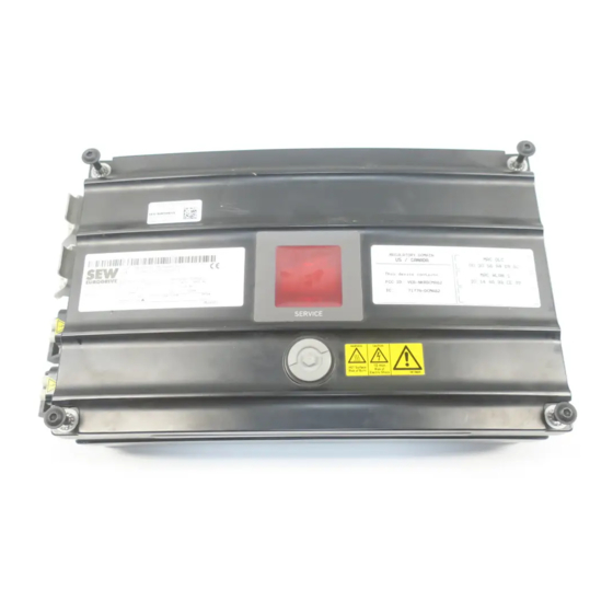
- Page 1 *23541253_0517* Drive Technology \ Drive Automation \ System Integration \ Services Revision Drive and Application Controller ® MOVIPRO PHE10A-..-3..A-00.. Edition 05/2017 23541253/EN...
- Page 2 SEW-EURODRIVE—Driving the world...
-
Page 3: Table Of Contents
Table of contents Table of contents Revision............................. 4 Device structure ........................ 5 Type designation...................... 5 Operating principle...................... 6 2.2.1 Power supply three-phase current with Ethernet interface ...... 6 Function units........................ 7 2.3.1 Communication and control unit.............. 7 Electrical installation........................ 8 Connection blocks...................... 8 3.1.1 Design with radio modem................ -
Page 4: Revision
Revision Revision ® This revision applies following documentation: "MOVIPRO PHE10A‑..‑3..A‑00.." operating instructions, edition 11/2016. Replacements • Chapter 3.1 "Type designation" is replaced by "Type designation" (→ 2 5). The sub-topic "Fieldbus interface" (→ 2 7) is replaced in chapter 3.8.2 "Commu- • nication and control unit". •... -
Page 5: Device Structure
Device structure Type designation Device structure Type designation The type designation contains the following data: ® PHE10A MOVIPRO drive and application controller Power supply: A = Three-phase current ® T = MOVITRANS Maximum S1 device power: 11 = 1.1 kW 15 = 1.5 kW Brake control: Control for 3-wire brakes from SEW‑EURODRIVE Design: 0 = Standard 2 = With pressure compensating valve... -
Page 6: Operating Principle
Device structure Operating principle Operating principle 2.2.1 Power supply three-phase current with Ethernet interface The block diagram below shows the basic structure of the device: X4233 X4022 RS485 DC 24V X5502 DC 24V X2011 X1201 RS485 DC24V X2211 20462899467 [A] – Communication and control unit Fieldbus connection, Controller type Service unit [B] –... -
Page 7: Function Units
Device structure Function units Function units 2.3.1 Communication and control unit The function module consists of the following internal elements. Fieldbus interface Depending on the design, one of the following communication options is available: Ethernet The device is equipped with a UDP-capable Ethernet interface for connection to the fieldbus. -
Page 8: Electrical Installation
Electrical installation Connection blocks Electrical installation Connection blocks WARNING Electric shock due to connecting or disconnecting plug connectors when voltage is applied. Severe or fatal injuries. • Disconnect all supply voltages. • Make sure that the device is de-energized. • Never plug or unplug the plug connectors while they are energized. -
Page 9: Design With Radio Modem
Electrical installation Connection blocks 3.1.1 Design with radio modem [13] [12] [11] [10] 36028810607195787 Power supply connection (→ 2 10) Auxiliary axis connection (→ 2 11) X2011 Motor with brake control X4022 RS485 interface – service (→ 2 24) X5502 Safe disconnection – input (→ 2 34) X5002_1 Digital inputs/outputs –... -
Page 10: Design With Ethernet Interface
Electrical installation Connection blocks 3.1.2 Design with Ethernet interface [11] [10] 20462903435 Power supply connection (→ 2 10) Auxiliary axis connection (→ 2 11) X2011 Motor with brake control (→ 2 16) X4022 RS485 interface – service (→ 2 24) X5502 Safe disconnection – input (→ 2 34) X5002_1 Digital inputs/outputs – communication and control unit (→ 2 31) X5002_3 Digital inputs/outputs –... -
Page 11: Auxiliary Axis Connection
Electrical installation Electrical connections 3.1.4 Auxiliary axis connection Type designation Connection ® PHE10A‑A..‑3.X1.. [1] "X2211: MOVIMOT auxiliary axis" (→ 2 21) ® PHE10A‑T..‑3.X1.. [1] "X2201: MOVIMOT auxiliary axis" (→ 2 19) Electrical connections 3.2.1 Representation of connections The wiring diagrams show the contact end of the connections. 3.2.2 Connection cables INFORMATION For more information on cable types, refer to the chapter Technical data. -
Page 12: Cable Structure
Electrical installation Electrical connections 3.2.3 Cable structure Diagram The following table shows the cable structure based on an example: Depiction Meaning Cable shield Number of core pairs (in twisted cables only) Number of cores G - with green-yellow PE conductor X - without PE 0.25 Core cross section in mm... -
Page 13: X1021: Movitrans Thm20C Pick-Up
Electrical installation Electrical connections ® 3.2.4 X1021: MOVITRANS THM20C pick-up Function ® Unit supply with MOVITRANS THM20C pick-up Connection type ® Q 4/2, female Wiring diagram Name Function ® THM Pole 1 MOVITRANS pick-up pole 1 n.c. Not connected ® THM Pole 2 MOVITRANS pick-up pole 2 n.c. -
Page 14: X1201: Ac 400 V Input
Electrical installation Electrical connections 3.2.5 X1201: AC 400 V input Function AC 400 V input to supply devices up to 16 kW Connection type ® Q 4/2, male Wiring diagram 4 PE Name Function Supply system phase 1 Supply system phase 2 Supply system phase 3 n.c. - Page 15 Electrical installation Electrical connections Cable Length/installation Component type Part number: 18150306 Cable design: (4G2.5) Variable length – ® ® Q 4/2 ↔ Han Q 4/2 male Part number: 18174213 Variable length – Cable design: (4G2.5) ® Q 4/2 ↔ Open with conductor end sleeves Part number: 18174221 Cable design: (4G2.5) Variable length...
-
Page 16: X2011: Motor With Brake Control
Electrical installation Electrical connections 3.2.6 X2011: Motor with brake control NOTICE Damage or malfunction due to use of motors with built-in brake rectifiers. Damage to the drive system or its environment. • Do not use motors with built-in brake rectifiers in conjunction with this device. Function Power connection for motor with brake up to 4 kW Connection type... - Page 17 Electrical installation Electrical connections Connection cables The following table shows the cables available for this connection. The cables are ap- proved up to 2.2 kW according to IEC / UL. Cables Length/ Component installation type Part number: 18125794 DRS71 – 90 Variable DRE80 –...
- Page 18 Electrical installation Electrical connections Conductor assignment Part number Signal name Color coding Black/U1 Black/V1 Black/W1 Black/1 18125794 Black/2 18143776 Black/3 Black/4 Black/5 PE connection Green-yellow + shield end (Inner shield) Connecting the hybrid cable The following figure shows the connection of the hybrid cable to the terminal box of the motor.
-
Page 19: X2201: Movimot ® Auxiliary Axis
Electrical installation Electrical connections ® 3.2.7 X2201: MOVIMOT auxiliary axis Function ® Power connection for MOVIMOT auxiliary axis with DC 560 V supply Connection type ® Q 8/0, female Wiring diagram Name Function DC link (+) n.c. Not connected DC link (-) +24V DC 24 V output Reference potential... - Page 20 Electrical installation Electrical connections Cables Length/installation Component type ® Part number: 18224520 Variable length MOVIMOT MM 03D‑503‑00 – Cable design: 4G1.5+(3X0.75)+(2X0.75) MM 22D‑503‑00 ® Q 8/0 ↔ APGX ® The following figure shows an example of the wiring of an external MOVIMOT with DC supply: X2201 ®...
-
Page 21: X2211: Movimot ® Auxiliary Axis
Electrical installation Electrical connections ® 3.2.8 X2211: MOVIMOT auxiliary axis Function ® Power connection for MOVIMOT auxiliary axis with AC 400 V supply Connection type ® Q 8/0, female Wiring diagram Name Function Supply system phase 1 Coding pin Supply system phase 3 +24V DC 24 V output Reference potential... - Page 22 Electrical installation Electrical connections Cables Length/installation Component type ® Part number: 18123511 Variable length MOVIMOT MM 03D‑503‑00 – Cable design: 4G1.5+(3X0.75)+(2X0.75) MM 22D‑503‑00 ® ® Q 8/0 ↔ Han Q 8/0 Conductor assignment Part number Signal name Color coding Black/L1 Black/L3 +24V Red/24 V White/0 V 11744995 Orange/RS+ Black/L2 Green/RS- Green/yellow...
-
Page 23: X4011: Rs485 Interface - External
Electrical installation Electrical connections 3.2.9 X4011: RS485 interface – external Function RS485 interface for external components Connection type M12, 5-pin, female, B-coded Wiring diagram Name Function +24V DC 24 V output RS485 data line (-) Reference potential RS485 data line (+) res. -
Page 24: X4022: Rs485 Interface - Service
Electrical installation Electrical connections 3.2.10 X4022: RS485 interface – service Function RS485 service interface Connection type RJ10 Wiring diagram Name Function Reference potential RS485 data line (-) RS485 data line (+) DC 5 V output Connection component USB11A interface adapter Part number: 08248311 Connection: RJ10 9007201799741963 ®... -
Page 25: X4111: Can Bus - External
Electrical installation Electrical connections 3.2.11 X4111: CAN bus – external INFORMATION If there is no station connected here, you must terminate the bus with a 120 Ω res- istor. Function CAN bus for external components Connection type M12, 5-pole, female, A-coded Wiring diagram Name Function... - Page 26 Electrical installation Electrical connections Cable Length/installation Component type Length 5 m: Part number: 13281402 Length 10 m: Part number: 13281410 Length 15 m: Part number: 13281429 Cable design: ((1X2X0.2)+(1X2X0.32)+1X0.32) Set length – M12, male, A-coded ↔ Open Conductor assignment Part number Signal name Color coding 13281348 CAN_SHLD –...
-
Page 27: X4211: Wlan Antenna (Main)
Electrical installation Electrical connections 3.2.12 X4211: WLAN antenna (main) INFORMATION If the connection is not used, you must terminate the bus with a 50 Ω resistor. Function Antenna connection for WLAN communication, parameterizable for send and receive functions Connection type R-TNC socket Wiring diagram Name... -
Page 28: X4233: Ethernet Fieldbus
Electrical installation Electrical connections 3.2.13 X4233: Ethernet fieldbus Function Ethernet fieldbus interface, 4-pin Connection type M12, 4-pin, female, D-coded Wiring diagram Name Function Sending cable (+) Receiving cable (+) Sending cable (-) Receiving cable (-) ® Revision – MOVIPRO PHE10A-..-3..A-00.. -
Page 29: X4261: Wlan Antenna (Aux)
Electrical installation Electrical connections 3.2.14 X4261: WLAN antenna (aux) INFORMATION If the connection is not used, you must terminate the bus with a 50 Ω resistor. Function Antenna connection for WLAN communication, parameterizable for send and receive functions Connection type R-TNC socket Wiring diagram Name... -
Page 30: X4401: Id Module
Electrical installation Electrical connections 3.2.15 X4401: ID module Function Interface for ID module from SEW‑EURODRIVE Connection type M12, 5-pole, male, A-coded Wiring diagram Name Function Reference potential IDM-Data ID module data line res. Reserved res. Reserved res. Reserved Connection component ID module Part number: 17974186 Connection M12... -
Page 31: X5002_1: Digital Inputs/Outputs - Communication And Control Unit
Electrical installation Electrical connections 3.2.16 X5002_1: Digital inputs/outputs – communication and control unit Function Digital inputs/outputs of the communication and control unit Connection type M12, 5-pole, female, A-coded Wiring diagram Name Function +24V DC 24 V output DI11 Data reception direction11 0V24 0V24 reference potential DI10... -
Page 32: X5002_2: Digital Inputs/Outputs - Communication And Control Unit
Electrical installation Electrical connections 3.2.17 X5002_2: Digital inputs/outputs – communication and control unit Function Digital inputs/outputs of the communication and control unit Connection type M12, 5-pole, female, A-coded Wiring diagram Name Function +24V DC 24 V output DI13/DO11 Data reception direction 13 oder Digital output nm 11 0V24 0V24 reference potential DI12/DO10... -
Page 33: X5002_3: Digital Inputs/Outputs - Communication And Control Unit
Electrical installation Electrical connections 3.2.18 X5002_3: Digital inputs/outputs – communication and control unit Function Digital inputs/outputs of the communication and control unit Connection type M12, 5-pole, female, A-coded Wiring diagram Name Function +24V DC 24 V output DI17/DO15 Data reception direction 17 oder Digital output nm 15 0V24 0V24 reference potential DI16/DO14... -
Page 34: X5502: Safe Disconnection - Input
Electrical installation Electrical connections 3.2.19 X5502: Safe disconnection – input WARNING Risk of injury due to non safety-related disconnection of the device if the connection is jumpered. Severe or fatal injuries. • Jumper this connection only if the device will not perform any safety functions ac- cording to EN ISO 13849‑1. - Page 36 SEW-EURODRIVE—Driving the world SEW-EURODRIVE GmbH & Co KG P.O. Box 3023 76642 BRUCHSAL GERMANY Phone +49 7251 75-0 Fax +49 7251 75-1970 sew@sew-eurodrive.com www.sew-eurodrive.com...
Need help?
Do you have a question about the MOVIPRO PHE10A 3 A-00 Series and is the answer not in the manual?
Questions and answers