
Related Manuals for Elektro-Automatik PSB 9000


Summary of Contents for Elektro-Automatik PSB 9000
- Page 1 Operating Guide PSB 9000 2.5 kW Bidirectional DC Power Supply Doc ID: PSB92EN Revision: 01 Date: 03/2020...
-
Page 3: Table Of Contents
PSB 9000 2.5 kW Series TABLE OF CONTENTS GENERAL About this document ........5 2.3.6 Grounding of the DC terminal ......32 1.1.1 Retention and use ..........5 2.3.7 Connecting the analog interface ....32 1.1.2 Copyright ............5 2.3.8 Connection of remote sense .......32 1.1.3... - Page 4 PSB 9000 2.5 kW Series 3.7.2 Device alarm and event handling ....57 Control panel (HMI) lock ......59 Limits lock .............60 3.10 Loading and saving a user profile ....60 3.11 The function generator.........61 3.11.1 Introduction...........61 3.11.2 General ............61 3.11.3 Method of operation ........62 3.11.4 Manual operation .........63 3.11.5...
-
Page 5: General
EA Elektro-Automatik guarantees the functional competence of the applied technology and the stated performance parameters. The warranty period begins with the delivery of free from defects equipment. Terms of guarantee are included in the general terms and conditions (TOS) of EA Elektro-Automatik. Limitation of liability All statements and instructions in this manual are based on current norms and regulations, up-to-date technology and our long term knowledge and experience. -
Page 6: Disposal Of Equipment
PSB 9000 2.5 kW Series Disposal of equipment A piece of equipment which is intended for disposal must, according to European laws and regulations (ElektroG, WEEE) be returned to the manufacturer for scrapping, unless the person operating the piece of equipment or an- other, delegated person is conducting the disposal. -
Page 7: Safety
PSB 9000 2.5 kW Series Safety 1.7.1 Safety notices Mortal danger - Hazardous voltage • Electrical equipment operation means that some parts can be under dangerous voltage. Therefore all parts under voltage must be covered! This basically applies to all models, though 60 V models according to SELV can’t generate hazardous DC voltage. -
Page 8: Responsibility Of The User
PSB 9000 2.5 kW Series 1.7.2 Responsibility of the user The equipment is in industrial operation. Therefore the operators are governed by the legal safety regulations. Alongside the warning and safety notices in this manual the relevant safety, accident prevention and environmental regulations must also be applied. -
Page 9: Alarm Signals
PSB 9000 2.5 kW Series 1.7.5 Alarm signals The equipment offers various possibilities for signalling alarm conditions, however, not for danger situations. The signals may be optical (on the display as text), acoustic (piezo buzzer) or electronic (pin/status output of an analog interface). All alarms will cause the device to switch off the DC terminal. The meaning of the signals is as follows: Signal OT • Overheating of the device • DC terminal will be switched off... -
Page 10: Specific Technical Data
PSB 9000 2.5 kW Series 1.8.3 Specific technical data Model 2.5 kW PSB 9060-120 PSB 9080-120 PSB 9200-70 AC supply Two phase (L-L): 208 V, ±10%, 45...66 Hz Voltage range, frequency Single phase (L-N): 220 / 230 / 240 V, ±10%, 45...66 Hz Leak current <... - Page 11 PSB 9000 2.5 kW Series Model 2.5 kW PSB 9060-120 PSB 9080-120 PSB 9200-70 Power regulation Adjustment range 0…2550 W 0…2550 W 0…2550 W Accuracy (at 23 ± 5 °C / 73±9 °F) < 1% P < 1% P < 1% P Line regulation at ±10% ΔU...
- Page 12 PSB 9000 2.5 kW Series Model 2.5 kW PSB 9360-40 PSB 9500-30 PSB 9750-20 AC supply Two phase (L-L): 208 V, ±10%, 45...66 Hz Voltage range, frequency Single phase (L-N): 220 / 230 / 240 V, ±10%, 45...66 Hz Leak current <...
- Page 13 PSB 9000 2.5 kW Series Model 2.5 kW PSB 9360-40 PSB 9500-30 PSB 9750-20 Power regulation Adjustment range 0…2550 W 0…2550 W 0…2550 W Accuracy (at 23 ± 5 °C / 73±9 °F) < 1% P < 1% P < 1% P Line regulation at ±10% ΔU...
-
Page 14: Views
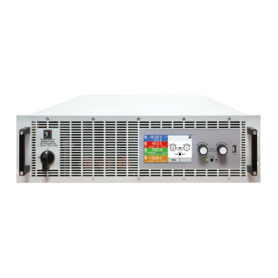
PSB 9000 2.5 kW Series 1.8.4 Views Figure 1 - Front view Figure 2 - Rear view (standard version) EA Elektro-Automatik GmbH Fon: +49 2162 / 3785-0 www.elektroautomatik.de Page 14 Helmholtzstr. 31-37 • 41747 Viersen Fax: +49 2162 / 16230 ea1974@elektroautomatik.de... - Page 15 PSB 9000 2.5 kW Series EA Elektro-Automatik GmbH Fon: +49 2162 / 3785-0 www.elektroautomatik.de Page 15 Helmholtzstr. 31-37 • 41747 Viersen Fax: +49 2162 / 16230 ea1974@elektroautomatik.de Germany...
- Page 16 PSB 9000 2.5 kW Series Figure 5 - Top view EA Elektro-Automatik GmbH Fon: +49 2162 / 3785-0 www.elektroautomatik.de Page 16 Helmholtzstr. 31-37 • 41747 Viersen Fax: +49 2162 / 16230 ea1974@elektroautomatik.de Germany...
-
Page 17: Control Elements
PSB 9000 2.5 kW Series 1.8.5 Control elements Figure 6- Control Panel Overview of the elements on the control panel For a detailed description see section „1.9.6. The control panel (HMI)“. Touchscreen display Used for selection of set values, menus and settings, as well as display of actual values and status. -
Page 18: Construction And Function
1.9.1 General description The power supplies of the PSB 9000 series are so-called bidirectional devices, incorporating the function of a lab- oratory power supply (source) and an electronic load (sink) into one unit. They allow for easy setup of applications according to the source-sink principle with a minimum of required hardware and cabling. -
Page 19: Scope Of Delivery
PSB 9000 2.5 kW Series 1.9.3 Scope of delivery 1 x Bidirectional power supply device 1 x Share Bus plug 1 x Remote sensing plug 1 x 1.8 m (5.9 ft) USB cable 1 x Set of DC terminal covers... -
Page 20: The Control Panel (Hmi)
PSB 9000 2.5 kW Series 1.9.6 The control panel (HMI) The HMI (Human Machine Interface) consists of a display with touch screen, two rotary knobs, a pushbutton and an USB port. 1.9.6.1 Touchscreen display The graphic touchscreen display is divided into a number of areas. The complete display is touch sensitive and can be operated by finger or stylus to control the equipment. - Page 21 PSB 9000 2.5 kW Series • Status display (upper right) This area displays various status texts and symbols: Display Description The HMI is locked The HMI is unlocked Remote: The device is under remote control from..Analog ..the built-in analog interface USB &...
- Page 22 PSB 9000 2.5 kW Series 1.9.6.4 Resolution of the displayed values In the display, set values can be adjusted in fixed increments. The number of decimal places depends on the device model. The values have 4 or 5 digits. Actual and set values always have the same number of digits. Adjustment resolution and number of digits of set values in the display:...
-
Page 23: Usb Port (Rear Side)
PSB 9000 2.5 kW Series File name Description Section 3.11.16.7 battery_test_log_<nr>.csv File with log data recorded from the battery test function. For a battery test log, data different and/or additional to log data of normal USB logging is recorded. mpp_result_<nr>.csv Result data from MPP tracking mode 4 in form of a table with 100 3.11.17.6... -
Page 24: Analog Interface
Following power supply and electronic load series are compatible: • PSB 9000 3U / PSB 9000 Slave • PSI 9000 2U - 24U / PSI 9000 3U Slave / PSI 9000 WR 3U / PSI 9000 WR 3U Slave • ELR 9000... -
Page 25: Gpib Port (Optional)
PSB 9000 2.5 kW Series 1.9.13 GPIB port (optional) The optional GPIB connector, which is available with option 3W, will replace the module slot of standard version devices. The device then offers a three-way interface with GPIB, USB and analog. The connection to a PC or other GPIB port is done with standard GPIB cables from stock, which can have straight or 90°... -
Page 26: Installation & Commissioning
PSB 9000 2.5 kW Series Installation & commissioning Transport and storage 2.1.1 Transport • The handles on the front side of the device are not for carrying! • Because of its weight, transport by hand should be avoided where possible. If unavoidable then only the housing should be held and not on the exterior parts (handles, DC terminal, rotary knobs). -
Page 27: Preparation
PSB 9000 2.5 kW Series 2.3.2 Preparation Mains connection for a device with a 2.5 kW power rating is done via the included 5 pole socket on the back of the device. Wiring of the included plug requires a 3 wire lead of suitable cross section and length. For recommendations about cable cross section see „2.3.4. -
Page 28: Connection To Ac Supply
PSB 9000 2.5 kW Series 2.3.4 Connection to AC supply • Connection to an AC supply must only be carried out by qualified personnel and the device must always be run directly on a power grid (transformer are permitted) and not on generators or UPS equipment! • Cable cross section must be suitable for the maximum input current of the device! See tables below. - Page 29 PSB 9000 2.5 kW Series 2.3.4.3 Strain relief and plug fixture There is a standard fixture mounted to the AC input con- nection block on the rear. It’s used to prevent the AC plug from loosening and disconnecting due to vibrations or similar. The fixture is also used as strain relief. Using the 4x M3 acorn nuts, it’s recommend to mount the fixture to the AC filter block every time the AC plug has been plugged again.
- Page 30 Protecting the electrical installation when using energy recovering devices A PSB 9000 device recovers energy and feeds it back into the local power grid. The generated current adds to the grid current (see schematic below) and this can lead to an overload of the existing installation. Considering any two outlets, no matter of what kind they are, there is usually no extra fusing installed.
-
Page 31: Connection To Dc Loads Or Dc Sources
PSB 9000 2.5 kW Series 2.3.5 Connection to DC loads or DC sources • In the case of a device with a high nominal current and hence a thick and heavy DC connec- tion cable it’s necessary to take account of the weight of the cable and the strain imposed on the DC connection. -
Page 32: Grounding Of The Dc Terminal
PSB 9000 2.5 kW Series 2.3.5.2 Cable lead and plastic cover A plastic cover for contact protection is included for the DC terminal. It should always be installed. The cover for type 2 (see picture above) is fixed to the connector itself, for type 1 to the back of the device. Furthermore the cover for type 1 has break outs so that the supply cable can be laid in various directions. -
Page 33: Installation Of An Interface Module
PSB 9000 2.5 kW Series Figure 8 - Example for remote sensing wiring with load in source mode (sink mode will be wired identically) 2.3.9 Installation of an interface module The optionally obtainable interface modules can be retrofitted by the user and are exchangeable with each other. The settings for the currently installed module vary and need to be checked and, if necessary, corrected on initial installation and after module exchange. -
Page 34: Connecting The "Share" Bus
The “Share” bus connector on the back side is usually connected to the Share bus connectors of further units of series PSB 9000, in order to balance the current between multiple units in parallel operation, especially when using the integrated function generator of the master unit. For further information about parallel operation refer to section „3.12.1. -
Page 35: Terms
PSB 9000 2.5 kW Series Operation and application Terms The device is a combination of a power supply and an electronic load. It can work alternatingly in one of two superior operation modes which are distinguished from each other in several parts of this document below: • Source / source mode:... -
Page 36: Current Regulation / Constant Current / Current Limiting
PSB 9000 2.5 kW Series The same occurs with a positive load step, i.e. low load to high load. There the output collapses for a moment. The amplitude of the overshoot or collapse depends on the device model, the currently adjusted output voltage and the capacity on the DC terminal and can thus not be stated with a specific value. -
Page 37: Internal Resistance Regulation (Source Mode)
The voltage on the DC input is equal to or lower than the voltage set value The PSB 9000 would not draw any current and enter CV mode. In a situation where the supplied input voltage is approx. equal to or oscillating around the voltage set value, the sink mode would permanently toggle between CV and CR. -
Page 38: Sink-Source Mode Switching
PSB 9000 2.5 kW Series 3.3.6 Sink-source mode switching The switchover between sink and source mode happens automatically and only depends on the device’s voltage setting and actual value on the DC terminal or the remote sense connector, if in use. -
Page 39: Alarm Conditions
PSB 9000 2.5 kW Series Alarm conditions This section only gives an overview about device alarms. What to do in case your device indi- cates an alarm condition is described in section „3.7. Alarms and monitoring“. As a basic principle, all alarm conditions are signaled optically (text + message in the display) and acoustically (if activated), as well as status via digital interface. -
Page 40: Safety Ovp
PSB 9000 2.5 kW Series 3.4.6 Safety OVP This extra feature is only built into the 60 V model of this series. Similar to the regular overvoltage protection (OVP, see 3.4.3), the Safety OVP is supposed to protect the application or people according to SELV. The alarm shall prevent the device from providing an output voltage higher than 60 V. -
Page 41: Manual Operation
PSB 9000 2.5 kW Series Manual operation 3.5.1 Switching on the device The device should, as far as possible, always be switched on using the rotary switch on the front of the device. Alternatively this can take place using an external cutout (contactor, circuit breaker) of suitable current capacity. - Page 42 PSB 9000 2.5 kW Series 3.5.3.1 Menu “General Settings” Setting Description Allow remote control Selection “NO” means that the device can’t be remotely controlled over either the digital or analog interfaces. If remote control isn’t allowed, the status will be shown as “local”...
- Page 43 PSB 9000 2.5 kW Series Setting Description DC terminal after remote Determines the condition of the DC terminal after leaving remote control either manually or by command: • OFF = DC terminal will be always off when switching from remote to manual • AUTO = DC terminal will keep the last condition Enable R mode Activates (“Yes”) or deactivates (“No”) the internal resistance control.
- Page 44 PSB 9000 2.5 kW Series IF Level 1 Description Node Address Selection of the Profibus or node address of the device within range 1...125 via direct input Function Tag String input box for a user-definable text which describes the Profibus slave function tag. Max. length: 32 characters Location Tag String input box for a user-definable text which describes the Profibus slave location tag. Max. length: 22 characters Installation Date String input box for a user-definable text which describes the Profibus slave installation date tag. Max. length: 40 characters Description String input box for a user-definable text which describes the Profibus slave. Max. length: 54 characters...
- Page 45 PSB 9000 2.5 kW Series IF Level 1 Level 2 Description Node Address Selection of the CANopen node address in the range 1...127 Baud Rate AUTO Automatic detection of the bus baud rate.(speed) Automatically sets baud rate and node address Manual Manual selection of the baud rate that is used by the CANopen interface.
- Page 46 PSB 9000 2.5 kW Series IF Level 1 Description The baud rate is selectable, other serial settings can’t be changed and are defined like this: 8 data bits, 1 stop bit, parity = none Baud rates: 2400, 4800, 9600, 19200, 38400, 57600, 115200 Element Description Com Timeout Timeout USB/RS232 (in milliseconds) Default value: 5, Range: 5...65535 Defines the max. time between two subsequent bytes or blocks of a transferred message.
-
Page 47: Adjustment Limits
Changing the operating mode In general, the manual operation of a PSB 9000 distinguishes between two or three operating modes, U/I and U/P and U/R, which are tied to set value input using the rotary knobs or ten-key pad. This assignment must be changed if one of the three or four set values is to be adjusted which is currently not assigned to any of the knobs. -
Page 48: Manual Adjustment Of Set Values
PSB 9000 2.5 kW Series 3.5.6 Manual adjustment of set values The set values for voltage, current and power are the fundamental operating possibilities of a power supply and hence the two rotary knobs on the front of the device are always assigned to two of the values in manual operation. -
Page 49: Switching The Dc Terminal On Or Off
PSB 9000 2.5 kW Series 3.5.7 Switching the DC terminal on or off The DC terminal of the device can be manually or remotely switched on and off. This can be restricted in manual operation by the control panel being locked. After switching it on, it either works as input (sink mode) or output (source mode). More information can be found in „3.3.6. Sink-source mode switching“. - Page 50 PSB 9000 2.5 kW Series 3.5.8.4 USB logging file format Type: text file in german/european or US american CSV format (depending on the selected setting) Layout (default german number format shown): Legend: U set: Voltage set value I set (PS) / P set (PS) / R set (PS): Set values from source mode I set (EL) / P set (EL) / R set (EL): Set values from sink mode...
-
Page 51: Remote Control
“Local” period. 3.6.3 Remote control via a digital interface 3.6.3.1 Selecting an interface The standard models of series PSB 9000 support, in addition to the built-in USB port, the following optionally available interface modules: Short ID Type Ports Description*... -
Page 52: Remote Control Via The Analog Interface (Ai)
PSB 9000 2.5 kW Series 3.6.3.2 General information about the interface modules With the standard models of series PSB 9000, one of the plug-in and retrofittable modules listed in 3.6.3.1 can be installed. It can take over remote control of the device alternatively to the built-in USB type B on the back side or analog interface. For installation see section „2.3.9. Installation of an interface module“ and separate documentation. - Page 53 PSB 9000 2.5 kW Series 3.6.4.2 Resolution The analog interface is internally sampled and processed by a digital microcontroller. This causes a limited resolu- tion of analog steps. The resolution is the same for set values (VSEL etc.) and actual values (VMON/CMON) and is 26214 when working with the 10 V range.
- Page 54 PSB 9000 2.5 kW Series * AI = Analog Input, AO = Analog Output, DI = Digital Input, DO = Digital Output, POT = Potential ** Internal Vcc approx. 10 V *** Only one of both signals possible, see section 3.5.3.1...
- Page 55 PSB 9000 2.5 kW Series Following situations can occur: • Remote control has been activated During remote control via analog interface, only pin “REM-SB” determines the states of the DC terminal, according to the levels definitions in 3.6.4.4. The logical function and the default levels can be inverted by a parameter in the setup menu of the device.
- Page 56 PSB 9000 2.5 kW Series c) Reading actual values The AI provides the DC terminal values as current and voltage monitor. These can be read using a standard multimeter or similar. d) Switching between source and sink mode You can also switch between both modes when remotely controlling the device with the AI. This is done using the voltage set value (VSEL), which then must not be tied to a fixed potential, like shown in example b). Rules:...
-
Page 57: Alarms And Monitoring
PSB 9000 2.5 kW Series Alarms and monitoring 3.7.1 Definition of terms There is a clear distinction between device alarms (see „3.4. Alarm conditions“) such as overvoltage protection or overheating protection, and user defined events such as OVD (overvoltage detection). Whilst device alarms serve to protect the device or the connected load or external source by initially switching off the DC terminal, user defined events can switch off the DC terminal (Action = ALARM), but can also simply give an acoustic signal to make the user aware. The actions driven by user defined events can be selected: Action... - Page 58 PSB 9000 2.5 kW Series These device alarms can’t be configured and are based on hardware: Short Long Description Indication AC supply over- or undervoltage. Triggers an alarm if the AC supply is out of specification or when the device is cut from supply, for example Display, analog & Power Fail when switching it off with the power switch. The DC terminal will be digital interface switched off. OverTem- Triggers an alarm if the internal temperature reaches a certain limit.
-
Page 59: Control Panel (Hmi) Lock
PSB 9000 2.5 kW Series These events shouldn’t be confused with alarms such as OT and OVP which are for device protection. User defined events can, however, if set to action ALARM, switch off the DC terminal and thus protect the load, like a sensitive electronic application. -
Page 60: Limits Lock
PSB 9000 2.5 kW Series Limits lock In order to avoid the alteration of the adjustment limits (also see „3.5.4. Adjustment limits“) by an unprivileged user, the screen with the adjustment limit settings (“Limits”) can be locked by a PIN code. The menu pages for the limits in SETTINGS and the profiles in MENU will then become inaccessible until the lock is removed by entering the correct PIN or in case it has been forgotten, by resetting the device as last resort. -
Page 61: The Function Generator
PSB 9000 2.5 kW Series 3.11 The function generator 3.11.1 Introduction The built-in function generator (short: FG) is able to create various signal forms and apply these to the set value of either voltage or current. The standard functions are based on an arbitrary generator and directly accessible and configurable using man- ual control. -
Page 62: Method Of Operation
PSB 9000 2.5 kW Series 3.11.2.3 Resolution Amplitudes generated by the arbitrary generator have an effective resolution of approx. 52428 steps. If the am- plitude is very low and the time long, the device would generate less steps and set multiple identical values after another, generating a staircase effect. It’s furthermore not possible to generate every possible combination of time and a varying amplitude (slope). 3.11.2.4 Possible technical complications Operation of switching mode power supplies as a voltage source can, when applying a function to the output volt- age, lead to damage of the output capacitors due to continuous charging/discharging which causes overheating. -
Page 63: Manual Operation
PSB 9000 2.5 kW Series 3.11.4 Manual operation 3.11.4.1 Function selection and control Via the touch screen one of the functions described in 3.11.1 can be selected, configured and controlled. This is only permissible while the DC terminal is switched off. ► How to select a function and adjust parameters While the DC terminal is switched off tap the touch area on the main screen. -
Page 64: Sine Wave Function
PSB 9000 2.5 kW Series 3.11.5 Sine wave function Restrictions which apply particularly to this function: • There is no preselection to which of both, source mode and sink mode, the function is applied to; the settings decide whether it’s “source mode only”, “sink mode only” or a mixture of both • When applying the function to the voltage, the device can only switch to and work in sink mode if the external... -
Page 65: Rectangular Function
PSB 9000 2.5 kW Series Schematic diagram: Application and result: A triangular wave signal for use on the current or voltage is generated. The positive and negative slope times can be set independently. The offset shifts the signal on the Y axis. The sum of the intervals t1 and t2 gives the cycle time and its reciprocal is the frequency. -
Page 66: Trapezoidal Function
PSB 9000 2.5 kW Series 3.11.8 Trapezoidal function Restrictions which apply particularly to this function: • There is no preselection to which of both, source mode and sink mode, the function is applied to; the settings decide whether it’s “source mode only”, “sink mode only” or a mixture of both • When applying the function to the voltage, the device can only switch to and work in sink mode if the external... -
Page 67: Arbitrary Function
PSB 9000 2.5 kW Series Schematic diagram: Application and result: If the function is set up to run in source mode, the built- in load function acts as a sink and ensures the quick output voltage drop as required for some parts of the curve, allowing the output voltage progress to follow the DIN curve. - Page 68 PSB 9000 2.5 kW Series After the settings for the selected sequence point are accepted with SAVE, further points can be configured. In a second settings screen, which can be reached by tapping NEXT in the sequence point selection screen, following global settings for all 99 points are adjustable: Value Range Description Start seq. 1...End seq. First sequence point in the block End seq.
- Page 69 PSB 9000 2.5 kW Series Schematic diagram: Applications and results: Example 5 Focussing 1 cycle of 1 sequence point: Similar to example 1 but with a start and end frequency of 0 Hz. Without a frequency no sine wave part (AC) will be created and only the DC settings will be effective. A ramp with a horizontal progression...
- Page 70 PSB 9000 2.5 kW Series Schematic diagram: Applications and results: Example 9 Focussing 1 cycle of 4 sequence points: Point 1: 1/4th sine wave (angle = 270°) Point 2: Three sine waves (ratio of frequency to sequence time: 1:3) Point 3: Horizontal ramp (f = 0)
-
Page 71: Ramp Function
PSB 9000 2.5 kW Series ► How to load a sequence table from an USB stick: Do not plug the USB drive yet or remove it. Access the function selection menu of the function generator with MENU -> Function Generator -> Arbitrary -> U/I, to see the main screen of sequence point selector, as depicted to the right. -
Page 72: Iu Table Function (Xy Table)
PSB 9000 2.5 kW Series Schematic diagram: Application and result: This function generates a rising or falling ramp between start and end values over the time t2. Time t1 creates a delay before the ramp starts. The function runs once and stops at the end value. To have a re- peating ramp, function Trapezoid would have to be used instead (see 3.11.8). -
Page 73: Simple Pv (Photovoltaics) Function
PSB 9000 2.5 kW Series ► How to load an IU table from an USB drive: Do not plug the USB drive yet or pull it out if already plugged. Open the function selection menu of the function manager with MENU -> Function Generator -> XY Table In the next screen select the desired function with either „IU Table (EL)“... - Page 74 PSB 9000 2.5 kW Series Schematic diagram: Application and result: Adjust all four parameters on screen to the desired values. While the simulation is running, the user can see from the actual values (voltage, current, power) of the DC output, where the operat- ing point of the power supply or of the simulated solar panel is.
-
Page 75: Fc Table Function (Fuel Cell)
PSB 9000 2.5 kW Series 3.11.14 FC table function (fuel cell) 3.11.14.1 Preface The FC table function is used to simulate the characteristics of voltage and current of a fuel cell. This is achieved by setting up some parameters which define points on a typical fuel cell curve, which is then calculated as UI table and passed to the internal function generator. -
Page 76: Extended Pv Function According To En 50530
PSB 9000 2.5 kW Series The function can be saved to USB stick as table, as well as read via any of the digital interfaces. In remote control, the function can’t be loaded or controlled. From the screen where the XY function generator is controlled manually (start/stop), you can go back to the first screen of the FC table function and use the formerly locked touch area to save the table to USB drive. In order to do so, follow the on-screen instructions. - Page 77 PSB 9000 2.5 kW Series 3.11.15.4 Simulation mode Apart from the panel technology there is also a simulation mode to select. Four options: Mode U/I Controllable simulation. Voltage (U , in V) and current (I , in A) in the maximum power point (MPP) are variable during runtime.
- Page 78 PSB 9000 2.5 kW Series 3.11.15.6 Interpolation The interpolation feature can calculate and set intermediate steps when running the PV function in day trend mode, i. e. DAY E/T or DAY U/I. The calculation is always done between to succeeding points on the day trend curve. The dwell time of every curve point is adjustable between 500 and 1,800,000 milliseconds (see above, format of the day trend data file). While there are no extra points calculated when using the minimum time of 500 ms, following...
- Page 79 PSB 9000 2.5 kW Series 3.11.15.8 Configuration step by step Starting point In MENU->Function Generator->2nd page->XY-Table you will find the PV functions. Select PV DIN EN 50530 (PS). Step 1: Technology selection The extended PV function requires to select the panel technology of the solar panel which is going to be simulated. In case cSI or Thin Film don’t match your requirements or you are not sure about their...
- Page 80 PSB 9000 2.5 kW Series Step 4: Global limits This configuration screen allows to limit voltage and power globally for the simulation. The current, in this table based simulation, is taken from the calculated PV table which also is an IU table. The output voltage of the power supply is already defined by setting up U in step 2, so it’s recommended to adjust value U to same or higher, else the PV curve may not be working as expected.
-
Page 81: Battery Test Function
PSB 9000 2.5 kW Series 3.11.16 Battery test function The purpose of the battery test function is to charge and discharge various battery types in industrial product tests or laboratory applications. Addition- ally, the so-called dynamic test mode combines a certain flow of charge and discharge phases while offering full configurability, for example which phase starts first or how much time in between both (pause) phases has to elapse or how often the charge/discharge cycle is going to be repeated. - Page 82 PSB 9000 2.5 kW Series 3.11.16.1 Settings for the static discharge mode The following parameters can be configured for the static discharge battery test function: Value Range Description 0...I Maximum discharge current (in Ampere) 0...P Maximum discharge power (in Watt) | OFF Maximum discharge resistance in Ω 3.11.16.2 Settings for the dynamic discharge mode...
- Page 83 PSB 9000 2.5 kW Series Value Range Description Action NONE, Separately defines an action for the settings „Discharge time“, “Charge SIGNAL, time”, “Discharge capacity“, “Charge capacity” and “Battery test time”. It End of test determines what shall happen with the test if any of the adjusted limits is reached: NONE = No action, test will continue SIGNAL = A text “Time limit”...
- Page 84 PSB 9000 2.5 kW Series 3.11.16.8 Possible reasons for battery test stop The battery test function run can be stopped by different reasons: • Manual stop on the HMI with button STOP • After the max. test time has been reached and action “End of test” was set for it • After the max.
-
Page 85: Mpp Tracking Function
PSB 9000 2.5 kW Series 3.11.17 MPP tracking function MPP stands for the maximum power point (see principle view to the right) on the power curve of solar panels. Solar inverters, when connected to such panels, constantly track this MPP once it has been found. - Page 86 PSB 9000 2.5 kW Series Following parameters can be configured for tracking mode MPP2: Value Range Description 0...U Voltage of the solar panel when unloaded, taken from the panel specs 0...I Short-circuit current, taken from the panel specs Δt 5 ms...60000 ms Interval for measuring U and I during the process of finding the MPP ΔP 0 W...0.5 P Tracking/regulation tolerance below the MPP 3.11.17.3...
-
Page 87: Remote Control Of The Function Generator
PSB 9000 2.5 kW Series ► How to load a curve data file for MPP4 While the DC terminal is switched off, enter the MENU and the Function Generator and access MPP Tracking. In the screen switch to tab MPP4. In the lower part a button labelled Import/Export will appear. Tap it. -
Page 88: Other Applications
In order for the Share bus to work correctly it requires at least to connect all DC minus terminals of the devices • The Share bus connection between multiple PSB 9000 units running in parallel is absolute- ly required, because it defines the operation mode (source/sink) for the slave units EA Elektro-Automatik GmbH Fon: +49 2162 / 3785-0 www.elektroautomatik.de... - Page 89 PSB 9000 2.5 kW Series A max. of 16 units can be connected via Share bus. 3.12.1.4 Wiring and set-up of the digital master-slave bus The master-slave connectors are built-in and can be connected via network cables (≥CAT3, patch cable). After this, MS can be configured manually or by remote control. The following applies: • A maximum of 16 units can be connected via the bus: 1 master and up to 15 slaves.
- Page 90 PSB 9000 2.5 kW Series ► Step 2: Configuring the master unit Enter , then GENERAL SETTINGS and press until reaching the master-slave settings. Specify the unit as master with touch area . A warning requester will appear which has to be acknowledged with OK, otherwise the change will be reverted.
-
Page 91: Series Connection
PSB 9000 2.5 kW Series • Loss of connection to any slave will result in shutdown of all DC terminals, as a safety measure, and the master will report this situation in the display with a pop-up “Master-slave security mode”. Then the MS system has to be re-initialised, either with or without re-establishing connection to the disconnected unit(s) before. -
Page 92: Operation As Battery Charger (Source Mode)
Operation as battery charger (source mode) A power supply (here: PSB 9000 in source mode) can be used as a battery charger, but with some restrictions, because it misses a battery supervision and a physical separation from the load in form of a relay or contactor, which is sometimes featured with real battery chargers as a protection. -
Page 93: Calibration
Preface The devices of series PSB 9000 don’t have a built- in feature to re-adjust the most important DC terminal related values, but they can still be readjusted using the software EA Power Control. The required calibration app is in- cluded in the free of charge base version of this software. -
Page 94: Contact And Support
PSB 9000 2.5 kW Series Contact and support Repairs Repairs, if not otherwise arranged between supplier and customer, will be carried out by the manufacturer. For this the device must generally be returned to the manufacturer. No RMA number is needed. It’s sufficient to package the equipment adequately and send it, together with a detailed description of the fault and, if still under guarantee, a copy of the invoice, to the following address. - Page 96 EA Elektro-Automatik GmbH & Co. KG Development - Production - Sales Helmholtzstraße 31-37 41747 Viersen Germany Fon: +49 2162 / 37 85-0 Mail: ea1974@elektroautomatik.de Web: www.elektroautomatik.de...
Need help?
Do you have a question about the PSB 9000 and is the answer not in the manual?
Questions and answers