Advertisement
Quick Links
Download this manual
See also:
User Manual
CONTROL PANEL
CA-64
(software version 1.03.xx)
System description and installation.
Przedsiębiorstwo Produkcyjno-Usługowe
GDAŃSK
ca64opis_e 06/01
Advertisement

Related Manuals for Satel CA-64


Summary of Contents for Satel CA-64
- Page 1 CONTROL PANEL CA-64 (software version 1.03.xx) System description and installation. Przedsiębiorstwo Produkcyjno-Usługowe GDAŃSK ca64opis_e 06/01...
- Page 2 „Help” system of the DLOAD64 program purchased with the alarm control panel or alternatively, at the web site www.satel.pl. In order to avail oneself of the system you need to install and run the program. Next, highlight the desired element of the program window (to do so, move the mouse pointer to and click the left mouse key on the element) and then press the F1 key on the computer keyboard.
-
Page 3: System Components
CA-64 SATEL System description and installation ♦ Possibility to define the names of users and of majority of system components (partitions, zones, outputs, modules). This facilitates the control and monitoring of system as well as viewing of events memory. ♦ Monitoring is made with the use of four different telephone numbers (two stations, each with a back-up number), with possibility to divide events into 8 identifiers. - Page 4 SYSTEM COMPONENTS ♦ 2 high-load outputs with electronic fuses for “power supply output” function. ♦ 2 connectors for voice synthesisers SM-2 or CA-64 SM. ♦ Communication bus for connection of LCD keypads; 8 LCD keypads and synoptic table module may be connected to it.
- Page 5 CA-64 SATEL System description and installation Expander for the proximity card reader or DALLAS chip reader ♦ one or two reading heads (entrance and exit registration), ♦ relay for electromagnetic door lock control, ♦ zone used for monitoring the relay (NC), ♦...
- Page 6 SYSTEM COMPONENTS 1.EXAMPLE OF CA-64 CONTROL PANEL CONFIGURATION RS-232 DOWNLOADING VIA EXTERNAL MODULE SERIES PRINTER DOWNLOADING TELEPHONE MONITORING LINK VOICE MESSAGING RS-232 12 OC TYPE ZASILACZ 3A OUTPUTS RS-232 PRINTER OUTPUTS 16 ZONES KEYPAD BUS LCD KEYPAD - 1 EKSPANDER BUS...
-
Page 7: Functional Description
CA-64 SATEL System description and installation FUNCTIONAL DESCRIPTION In this section, basic information on CA-64 control panel features is given, as defined in the software stored in FLASH memory. Windows of DLOAD64 version 1.03.08 are used in descriptions. Subsystems CA-64 control panel makes possible to create up to 8 subsystems. They are treated as separate alarm systems. - Page 8 Department workers do not enter the book-keeping office rooms, if they are not provided with authorisation of arming and disarming the “Book-keeping” partition. CA-64 control panel makes possible to create few partition types: • Partition armed with a code – basic partition type. Arming is done by the user.
- Page 9 CA-64 SATEL System description and installation • Access according to timer – the partition controlled by the user, but partition arming may be carried out only within time periods determined by timers selected. Partition cannot be armed and disarmed in time periods other than time periods determined by timers.
- Page 10 FUNCTIONAL DESCRIPTION If the object is watched by guard, the round monitoring and signalling of guard absence in specified time is possible – when the guard types his code on a partition or lock keypad; this is registered in the memory of events. Times connected with that are declared for each partition separately;...
- Page 11 RAM memory with battery backup. These are the codes for everyday operation of the system. 192 user codes may be entered in CA-64 control panel. NOTE: Taking into account safety of the system (unauthorised persons may peep at the code), it is recommended to assign a code from the group of user codes, with proper limitation of rights, to the administrator for his everyday usage.
- Page 12 (when monitoring in Ademco Contact ID format is activated). Monitoring The CA-64 control panel phone communication unit may monitor events to two stations. Two telephone numbers are assigned for each station (basic and backup ones), and the possibility of determining different transmission formats is provided.
- Page 13 CA-64 SATEL System description and installation When the “Monitor for Station 1 or 2” mode is on, the control panel dials in the following sequence: station 1 basic number, station 1 backup number, station 2 basic number, station 2 backup number, station 1 basic number and so on, until the number of trials determined for each station is reached.
- Page 14 FUNCTIONAL DESCRIPTION Fig. 6. Widow for assigning partition events to identifiers. • For pulse formats and Ademco Express it is necessary to program event codes. Only those events are transmitted, which are assigned to a valid identifier (e.i. those, which have at least three characters different from “0”) and which code is different from “00”.
- Page 15 CA-64 SATEL System description and installation the identifier of the subsystem, which “is responsible” for the system (for example, subsystem, where the control panel is installed). • For E format, assignation of partition, zones, keypads and expanders to identifiers does not need to reflect the division of the system into subsystems. But it is essential to program the value different than “0”.
- Page 16 “Panel restart” that will be followed by “Data restore”. • “Control Panel Restart” appears at each power supply connection. • Control panel CA-64 allows a monitoring test of two types: transmitting the event “Periodical reporting Test” either every day at a specified time or after a programmed time period from the last communication with the station (it is possible to activate the both types simultaneously).
- Page 17 System description and installation Messaging Function of messaging, featured by the control panel CA-64, allows informing on alarms with messages sent from voice synthesisers or transmitted to pagers. Messaging is made independently from monitoring, where monitoring has priority. If during messaging events occur on which the control panel must inform the monitoring station, monitoring will be included between pieces of information.
- Page 18 Answering a phone call The control panel CA-64 is provided with the function of answering external phone calls, called in the same way as when starting programming by telephone (double calling after a defined number of “rings”...
- Page 19 Remote programming Two programmes, DLOAD64 for use by the service (installer) and GUARD64 for use by the user, allow control panel CA-64 programming and control. Both programmes run in Windows95/98 environment. Control panel CA-64 is provided with several mechanisms of programming by means of computer: •...
-
Page 20: Control Panel Installation
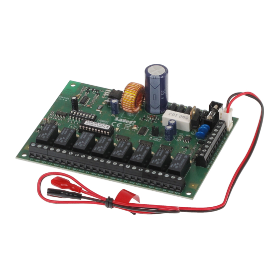
• When the control panel is connected to the computer, the STARTER program may be stopped by calling the command “ Restart CA-64” in the FLASH64 program ( Ctrl-F2, then indicate the port, to which the control panel is connected) CONTROL PANEL INSTALLATION Control panel CA-64 should be installed in closed rooms with normal air humidity. - Page 21 R-1 T-1 RING TIP 5W 0.1ΩJ T3.15A BATTERY BLACK Fig. 12. The arrangement of units on the CA-64 control panel.
- Page 22 Connection of LCD keypads Up to eight independent LCD keypads, designed for control and programming the alarm system, may be connected to the control panel CA-64. When some keypads are being connected to the control panel, connect them in parallel. Since keypad bus data are addressed, all keypads operate independent of each other.
- Page 23 CA-64 SATEL System description and installation The control panel identifies the keypads tracking addresses set by means of jumpers at the keypad board. The addresses must be unique! A keypad address also determines the numbers of keypad watching zones Z1 and Z2. These zones are operated by the control panel in the same way as main board zones.
- Page 24 CONTROL PANEL INSTALLATION keypad cannot exceed 100 metres. Keypad connector signals are shown in Figure SERIAL PORT COMPUTER RS-232 DSR keyp. DTR comp. TXD comp. RXD keyp. TXDkeyp. RXD comp. KEYPAD Fig. 14. Connection of the computer to the LCD keypad RS-232 port. NOTE: Switch on the “RS communication”...
- Page 25 LED keypads). Connection of expansion modules Control panel CA-64 is provided with two buses designed for connecting the expansion modules (expanders). Both buses have the same priority and are serviced in parallel (in has no meaning, which modules are connected to each bus). All modules are connected in parallel, and up to 32 modules may be connected to each bus.
- Page 26 CONTROL PANEL INSTALLATION common electronic circuit breaker (limitation 3A), the presence of power supply voltage is signalled by the sixth LED in the electronic circuit breaker block. Modules may be connected with the use of a typical, non-screened cable used in alarm systems (for example, DY8x0,5).
- Page 27 CA-64 SATEL System description and installation Each module connected to the bus should have its own, unique address. It has no meaning, which addresses are set for individual modules (the control panel receives an information on module type and automatically sets optimum sequence of calling the modules for data).
- Page 28 (and other, which are provided with operation signalling for service only) change their status. Connection of detectors CA-64 may operate with any detectors. Each control panel zone and zones of LCD keypads and zone modules may operate in the following configurations: • NC (normally closed), •...
- Page 29 Figure 16 (point “Connection of expansion modules”). Connection of signallers Control panel CA-64 is provided with 16 outputs, application of which may be programmed. In order to connect a signaller to the control panel, it is necessary to program this output as an alarm output.
- Page 30 CONTROL PANEL INSTALLATION NOTES: • Outputs OUT1..OUT4 are provided with a load presence detection unit, which is active when output is not active. If a load is connected correctly and the control panel indicates failure “No load present...”, connect a 2,2 k Ω resistor in parallel to the load.
- Page 31 SM-2 connectors. When a larger number of messages is needed, it is necessary to use the expander module type CA-64 SM. These synthesizers are controlled via the extension bus, and audio signals are connected to SYNT1 or SYNT2 terminals.
- Page 32 CONTROL PANEL INSTALLATION Connection of service computer In case of control panel CA-64 programming with the use of a computer and the “Downloading” function via control panel RS-232 port, the computer should be connected according to Figure 24. It is possible to connect the computer by means of the cable used for programming of CA-10 control panels.
- Page 33 CA-64 SATEL System description and installation the parameter block stored as “profile 0” („STORED PROFILE 0” in Figure 26) it must be specified E1 Q0 V1 X4 &D2 &S0 and S00:000. DSR cont.p. DSR modem RTS cont.p. RTS modem RXD cont.p.
- Page 34 CONTROL PANEL INSTALLATION 4) after parameter values are set according to the list described in point 2), store the settings in the “profile 0” (with command at&w0 ). 5) At the end, you may check whether all parameters are stored correctly – after the command atz , and then at&v , settings in ACTIVE PROFILE should be the same as in STORED PROFILE 0 (note: often STORED PROFILE set contains less number of parameters than ACTIVE PROFILE set, this is normal).
- Page 35 1) First program STARTER starts and checks contents of the control panel program memory. During this operation, LED adjacent to telephone line transmitter flashes and message STARTER 2.2 of control panel CA-64 is shown on LCD keypad displays. When the contents of FLASH program memory is correct, STARTER starts the program of the control panel.
-
Page 36: Starting The Control Panel
CONTROL PANEL INSTALLATION settings only. User data must be programmed again. Data on administrator and service codes are stored in the separate EEPROM memory and they are not lost after removal of jumper MEMORY. STARTING THE CONTROL PANEL Correctly installed control panel should start after mains power supply is switched on, as described in point Starting the system. - Page 37 (function in “TS configuration” position). Entering the service mode “with the use of pins” may be restored after approval of factory setting restoration. When exiting the service mode, the control panel CA-64 checks whether parameter values programmed by the service have changed. The message “Wait...” appears on LCD control panel display.
- Page 38 RS-232 to the computer, in which DLOAD64 is started, then, the function switches on the control panel power supply. NOTE: To protect data, CA-64 allows blocking of downloading function “with the use of pins”. Service mode function “DWNL-RS block” (function in „TS...
- Page 39 CA-64 SATEL System description and installation Programming by telephone When restart with restoration of factory settings is already made for the control panel, the telephone number of service computer must be programmed to start programming. Proceed as follows: 1. Enter the service mode, 2.
- Page 40 BASIC TECHNICAL DATA Basic technical data Main board supply voltage ..............20...24V AC Control panel current consumption ............... 120mA Nominal power supply unit voltage ..........13,6 - 13,8 V DC Power supply unit output current ................. 3A LCD keypad current consumption, min. / max......... 60/125mA Output OUT1 ...
- Page 41 CA-64 SATEL System description and installation SATEL s.c. 80-172 Gdańsk; POLAND ul. Schuberta 79 tel. (58) 32 09 400; (39) 12 47 27 Technical Department (58) 32 09 420; (604) 166 075 www.satel.pl satel@satel.pl...
Need help?
Do you have a question about the CA-64 and is the answer not in the manual?
Questions and answers