Satel CA-6 Installer Manual
Alarm control panel
Hide thumbs
Also See for CA-6:
- Programming manual (40 pages) ,
- User manual (18 pages) ,
- Quick user manual (9 pages)
Table of Contents
Advertisement
Advertisement
Table of Contents

Related Manuals for Satel CA-6


Summary of Contents for Satel CA-6
- Page 1 INSTALLER MANUAL 1 1 1 1 1 ca6i_e 07/06...
- Page 2 (European Directives 91/157/EEC and 83/86/EEC). DECLARATION OF CONFORMITY Manufacturer: SATEL spółka z o.o. Products: CA6P – mainboard of CA-6 control ul. Schuberta 79 80-172 Gdańsk, POLAND panels. tel. (+48 58) 320-94-00 fax.
-
Page 3: Table Of Contents
CONTENTS GENERAL DESCRIPTION OF THE CONTROL PANEL ............2 DESCRIPTION OF THE CONTROL PANEL ................2 Zones ........................... 2 Outputs..........................4 Partitions ..........................8 Access Codes and Authority Levels ..................8 Keypads ..........................9 Monitoring .......................... 10 Dialer..........................10 Remote Programming – DOWNLOADING................. 11 INSTALLATION OF THE CONTROL PANEL ................ -
Page 4: General Description Of The Control Panel
DESCRIPTION OF THE CONTROL PANEL Zones In its basic configuration, the CA-6 control panel has 8 zones: 6 on the panel main board and 2 in the keypad. The zones can support any detectors in the configuration NC, NO, EOL, 2EOL/NC, 2EOL/NO. - Page 5 CA-6 SATEL The zones (input lines) can perform the following functions in the system: 00 - exit/entry - the violation of which, when in the armed mode, will start countdown of the entry delay time and will enable the delay for INTERIOR DELAY type zones (violation of an INTERIOR DELAY zone without prior violation of the ENTRY/EXIT zone will trigger an alarm immediately).
-
Page 6: Outputs
In case of messaging to the telephone monitoring stations, five event codes sending to the monitoring stations can be determined for each zone. The CA-6 has an additional CTL input, which is intended for arming or disarming. It can also be used for connecting the panic, fire or emergency button. - Page 7 CA-6 SATEL All outputs are equipped with protection for inductive loads and pulse interference. Assignment of the particular outputs can be restricted to the specific partitions / zones of the system. For each output can be defined the operation time in seconds (from 1 to 99 seconds), in minutes (from 1 to 99 minutes), or LATCH type (until switch off).
- Page 8 SATEL Installer Manual 07 - keypad aux. alarm - the output starts on triggering the alarm by the user with the ALARM AUX function. The output can remain active for a specified time (from 01 to 99 seconds or from 01 to 99 minutes) or until the alarm is cleared by the user.
- Page 9 CA-6 SATEL 18 - telephone usage status - the output is active when the control panel is on the telephone line. 19 - ground start - the output is activated by the control panel if the GROUND START signal is to be generate (a 2 sec. signal occurring before the control panel "lifts the handset"...
-
Page 10: Partitions
41 - battery low status - the output, which state is updated after each battery voltage test. Partitions A new partition is created when at least one zone is assigned to it. The CA-6 permits creating of two partitions to which any outputs, telephone numbers and pager messages can be assigned, and thus enables two alarm systems to be built on the basis of one CA-6 control panel. -
Page 11: Keypads
The following features are also provided: • Setting the keypad backlight mode with the key 9: none, automatic, permanent. In the CA-6 KLED keypad, the backlighting can be switched on/off by means of pins located next to the terminal block on the keypad board. -
Page 12: Monitoring
Dialer The CA-6 is equipped with a telephone dialer, which enables an alarm voice message to be transmitted. The message is stored in an external synthesizer. The control panel directly interfaces with the SATEL SM-2 voice synthesizer. The dialer can also establish connections with paging systems. -
Page 13: Remote Programming - Downloading
Remote Programming – DOWNLOADING In order to facilitate programming, the CA-6 is equipped with a DOWNLOADING function, which enables a PC computer to be used for programming and controlling of the alarm system by means of the DLOAD10 program. -
Page 14: Installation Of The Control Panel
SATEL Installer Manual computer back, the panel notifies the monitoring station that the programming has started. 2. The computer calls the control panel and, after the communication passwords exchange, the control panel immediately proceeds to the exchange of data. This simplified mode of establishing communication is reached when the computer telephone number is not entered in the control panel. - Page 15 16V AC. The CA-6 main board enables a grounding circuit to be connected. The ground lead terminal is designated by the symbol.
- Page 16 (a faucet or a heater) with the top of his hand. The CA-6 control panel should be installed in an enclosed space with normal humidity of air. The space should be fitted with an available permanent (not detachable) 230V power supply circuit with protective grounding.
-
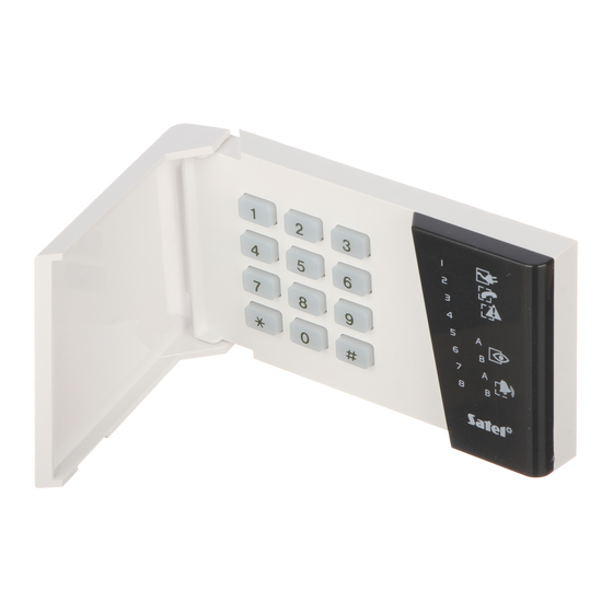
Page 17: Connection Of Keypad
There are three types of keypads designed to work together with the CA-6 control panel. All of them should be connected in the way shown in Fig. 4 for the CA-6 KLED keypad. For description of other keypad terminals, see the figures below. - Page 18 Z1 – to detector Additional system zones Z2 – to detector TAMPER CONTACT BUZZER Fig. 5. View of the CA-6 KLED-S keypad board. BUZZER TAMPER CONTACT KEYPAD ADDRESS WIRE CONNECTION TERMINALS Z1 COM DATA CLK +KPD Fig. 6. View of the CA-6 KLED-M keypad board.
-
Page 19: Connection Of Detectors
SATEL Connection of Detectors The CA-6 can operate with detectors of any type. Each zone of the control panel can work in the configuration NC, NO, EOL, 2EOL/NO, 2EOL/NC. When the zone works in an EOL configuration, a 2.2 kΩ resistor should be used to make the detector circuit. In case of 2EOL configuration, the detector circuit is closed by two 1.1 kΩ... - Page 20 SATEL Installer Manual +12 V LIMITER LIMITER LIMITER LIMITER 2,2A 2,2A 2,2A 1.5A OUT1 OUT2 OUT3 +KPD LOAD LOAD LOAD Fig.8. Connection of a load to high-current outputs. In the case of sirens which alarm after power is supplied, it is convenient to assign the alarm function to the OUT1 and OUT2 outputs.
-
Page 21: Connections Of Telephone Line
CA-6 SATEL NR2-DSC transmitter socket CA-6 (PGM) low-current outputs (TAKT) connector OUT4 output OUT5 output to battery "+" DB-15 fuse WTAT250V/2A to mainboard AC terminal to COM terminal (next to OUT1 terminal) Fig. 10. Connection of NR2-DSC transmitter, made by NOKTON. -
Page 22: Connection Of Voice Synthesizer
Before connecting the control panel to its power supply circuit, make sure that the supply circuit is not alive Description of electric connections for CA-6 OBU housing. 1. Connect the 230V alternating voltage leads to the transformer terminals marked "AC 230V". -
Page 23: Starting The Control Panel
CA-6 SATEL As the control panel has no isolating switch to disconnect the mains supply, it is important that the owner or the user of the security system be informed on how the system is to be disconnected from the mains (e.g. by indicating the fuse which protects the control panel supply circuit). -
Page 24: Activating Selected Functions
You should also program in FS95 what kind of message will be sent - if no message is selected for the pager, the CA-6 will use a voice message from the synthesizer. When the above parameters are correctly programmed and the alarm is triggered, the on- board LED (designated as „DIALER”) should go on, which indicates that the panel has... -
Page 25: Reporting To Telephone Monitoring Station
CA-6 SATEL line monitoring” jack in the SM-2 synthesizer (parallel connection of a telephone set to „monitor” the communication will interfere with the messaging operation). The telephone messaging will start immediately after triggering the alarm. Alarm clearing will interrupt the telephone messaging. - Page 26 It is possible to activate the options 7 and 8 in FS47, which makes the panel ignore the codes unacknowledged in 16 consecutive retries. Problems of this type do not occur in professional, multi-format monitoring stations (including the Satel STAM-1).
-
Page 27: Downloading - Communication With Computer
The programming is possible with the use of a special cable intended for programming the CA-5 and CA-6 control panels. To run the software, select a suitable COM port number in the DLOAD10 program (CONFIGURATION window). Then, from the Communication →... - Page 28 • start the DLOAD10 program, select the CA6 control panel type (e.g. by opening the data of such a panel) and, from the menu „Communication”, select “Modem” and „local” or „CA-6 without keypad” connection mode. Further procedure will be prompted by the program. The „CA-6 without keypad” command in the „Initializing modem”...
-
Page 29: Dload10 Program
The DLOAD10 program, delivered with the control panel, is designed for programming the CA-5, CA-6, CA-10 control panels, as well as the RX-2K, RX-4K and RE-4K radio controllers, the GSM-4 module and the ACU-100 wireless system controller, from the computer. -
Page 30: Program Configuration For Communication With The Control Panel
SATEL Installer Manual Program configuration for communication with the control panel In order to begin configuration, click on the icon to open the „Configuration” window. The „Port RS-232” tab permits selecting the computer port number in the case of direct programming through the panel RS port. -
Page 31: Default Settings
CA-6 SATEL The type of control panel is recognized automatically on establishing connection, or can be selected through the „File” menu. Calling the function of reading the control panel data (icon ) after the communication has been established may speed up the subsequent process of saving the changes in the control panel settings. - Page 32 An efficient security system does not prevent burglary, assault or fire from happening, however it diminishes the risk that such a situation will cause no alarm or notification. Therefore, the SATEL Company recommends that operation of the whole security system be regularly tested.
- Page 33 17...24V AC see: p. 4 high-current programmable keypads terminals outputs (description of sirens (description of keypads connection - see: p. 18) connection - see: p. 15) CA-6 Control Panel connection diagram (detailed description of main board terminals - see p. 12).
- Page 34 SATEL sp. z o.o. ul. Schuberta 79 80-172 Gdańsk POLAND tel. + 48 58 320 94 00 info@satel.pl www.satel.pl...
Need help?
Do you have a question about the CA-6 and is the answer not in the manual?
Questions and answers