
Subscribe to Our Youtube Channel
Related Manuals for Power One AURORA PVI-STRINGCOMB


Summary of Contents for Power One AURORA PVI-STRINGCOMB
- Page 1 ® AURORA OXES FOR THE CONNECTION OF STRINGS FOR PHO TOVOLTAI C AP PLIC ATIONS INSTALLATION AND INSTRUCTION MANUAL Models: PVI-STRINGCOMB / PVI-STRINGCOMB-S PVI-STRINGCOMB-MC / PVI-STRINGCOMB-S-MC Rev. 1.0...
- Page 2 Revision Description A. Morucci New StringComb 04-09-09 D.Nocentini S. Soldani 3L11 A. Morucci New StringComb 14-10-09 D.Nocentini S. Soldani 3L11 POWER-ONE: Complete or partial reproduction of this document by any means whatsoever is strictly forbidden without the authorization of Power-One...
-
Page 3: Table Of Contents
Operation and installation manual Page 3 of 96 (PVI-STRINGCOMB (-S, -MC, -S-MC) - Rev:1.0) CONTENTS GENERAL INSTRUCTIONS ON THE USE AND READING OF THIS MANUAL ........................... 8 ..................... 8 ISPOSAL OF WASTE .................... 9 RODUCT LABELLING ................. 9 YMBOLS USED IN THIS ANUAL PVI-STRINGCOMB(-S) .......... - Page 4 Operation and installation manual Page 4 of 96 (PVI-STRINGCOMB (-S, -MC, -S-MC) - Rev:1.0) TRANSPORT AND STORAGE ................35 INSTALLATION ..................... 36 ..................36 LACE OF INSTALLATION ....................... 38 OSITIONING .................. 40 LECTRICAL ONNECTION 9.3.1 Removal of the guards ................40 9.3.2 Serial Communication ................
- Page 5 Operation and installation manual Page 5 of 96 (PVI-STRINGCOMB (-S, -MC, -S-MC) - Rev:1.0) MONITORING AND CONFIGURATION INTERFACE ......63 12.1 ................... 63 ONVENTIONS USED 12.2 ....................63 CCESS LEVELS 12.3 ..................64 IRST INSTALLATION 12.4 ................67 SSIGNING THE IELD UMBER 12.4.1...
- Page 6 Operation and installation manual Page 6 of 96 (PVI-STRINGCOMB (-S, -MC, -S-MC) - Rev:1.0) INDEX OF FIGURES: 1-1: P ) ................9 IGURE RODUCT LABEL EXAMPLE 1-2: P ..............9 IGURE OWER INPUTS AND OUTPUTS LABEL 2-1: A ..................13 IGURE RRAY COMPOSITION 3-1: E...
- Page 7 Operation and installation manual Page 7 of 96 (PVI-STRINGCOMB (-S, -MC, -S-MC) - Rev:1.0) 9-19: U ........54 IGURE SE THE SPECIAL SCREWDRIVER ON THE TERMINALS 9-20: C ........55 IGURE ABLE GLAND FOR NEGATIVE STRINGS CONNECTION 9-21: LED ............56 IGURE INDICATING NORMAL OPERATION 12-1: E...
-
Page 8: General Instructions On The Use And Reading Of This Manual
Power-One shall accept no responsibility for damages consequent to the use of unsuitable spare parts. Power-One reserves the right to make any amendments to this Manual and to the device without advance notice: the most recent version of the Manual, indicating the revision number, is available at the site (www.power-one.com... -
Page 9: Product Labelling
(PVI-STRINGCOMB (-S, -MC, -S-MC) - Rev:1.0) Product labelling Figure 1-1: Product label (example) The identification label affixed to the PVI-STRINGCOMB(-S) contains the following information: 1) Power-One product's production code 2) Model name 3) Serial number 4) Week/Year of production 5) Serial address RS485 6) Product revision Figure 1-2 shows the label specifying input and output polarities. - Page 10 Operation and installation manual Page 10 of 96 (PVI-STRINGCOMB (-S, -MC, -S-MC) - Rev:1.0) To reduce the risk of electric shock, and to ensure that the device is correctly installed and ready for use, special safety symbols are used in the Manual to indicate potential risks or useful information.
-
Page 11: Symbols Used On The Pvi-Stringcomb(-S)
Operation and installation manual Page 11 of 96 (PVI-STRINGCOMB (-S, -MC, -S-MC) - Rev:1.0) Symbols used on the PVI-STRINGCOMB(-S) The device has various labels; those with a yellow background regard the safety devices provided. Make sure that you have read and fully understand the labels before installing the device. -
Page 12: General Information And Features Of A Photovoltaic System
Operation and installation manual Page 12 of 96 (PVI-STRINGCOMB (-S, -MC, -S-MC) - Rev:1.0) GENERAL INFORMATION FEATURES PHOTOVOLTAIC SYSTEM This chapter gives the PVI-STRINGCOMB(-S) user general information on photovoltaic plants which transform solar energy into electricity, which can be used in the mains network. Photovoltaic energy In the energy transformation process, industrialised companies (the greatest energy consumers) have been experimenting methods for energy saving and for... -
Page 13: Fundamental Elements Of A Photovoltaic Field: "Strings" And "Arrays
Operation and installation manual Page 13 of 96 (PVI-STRINGCOMB (-S, -MC, -S-MC) - Rev:1.0) According to national and local standards and regulations the produced energy can be sold to the grid or credited to the user against future consumption, thus granting a great saving of money. - Page 14 There are several factors and considerations to be taken into account when designing a photovoltaic system, such as the type of panels, available room, location, long-term target output, etc. The system configurator available on Power-One's web site (www.power-one.com) may help in sizing a photovoltaic system.
-
Page 15: Large Phv Fields And Parallel Strings
Operation and installation manual Page 15 of 96 (PVI-STRINGCOMB (-S, -MC, -S-MC) - Rev:1.0) LARGE PHV FIELDS AND PARALLEL STRINGS. When speaking of large photovoltaic fields, the immediate image is one of large extensions of solar panels. Since a field (array) is composed of several parallel strings, it is clear that to obtain high power the number must be increased. -
Page 16: Figure 3-1: Effect Of A Panel Breakdown With Short-Circuit
Operation and installation manual Page 16 of 96 (PVI-STRINGCOMB (-S, -MC, -S-MC) - Rev:1.0) The fuse rating must be chosen by taking into consideration the maximum current that can flow through the fuse (also based on the number of strings connected to the channel in the parallel string panel) and the maximum inverted current that each string can take. -
Page 17: Figure 3-2: Intervention Of Protective Fuse
Operation and installation manual Page 17 of 96 (PVI-STRINGCOMB (-S, -MC, -S-MC) - Rev:1.0) Figure 3-2: Intervention of protective fuse With PVI-STRINGCOMB(-S), the connected strings are protected and controlled. In addition, information on the string currents, and other information, can be recorded, which can be useful during system operation. -
Page 18: Field Of Application And General Description Of The Parallel String Panel (Psp)
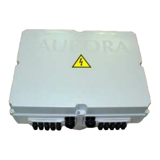
Operation and installation manual Page 18 of 96 (PVI-STRINGCOMB (-S, -MC, -S-MC) - Rev:1.0) FIELD OF APPLICATION AND GENERAL DESCRIPTION OF THE PARALLEL STRING PANEL (PSP) Figure 4-1: PVI-STRINGCOMB(-S) The PVI-STRINGCOMB(-S) and its variants (Figure 4-1) are devices designed exclusively for parallel connection of the photovoltaic field strings, allowing for protection in the case of breakdown. - Page 19 Operation and installation manual Page 19 of 96 (PVI-STRINGCOMB (-S, -MC, -S-MC) - Rev:1.0) Thanks to the 10 channels available, each device allows for connecting up to 10 strings individually, or 20 strings in parallel pairs. This is made possible thanks to the double-hole terminal board on each channel (from 1 to 10).
- Page 20 Operation and installation manual Page 20 of 96 (PVI-STRINGCOMB (-S, -MC, -S-MC) - Rev:1.0) Every device can be powered by an external source (24V DC). This allows the PVI-STRINGCOMB(-S) to remain running also during the night. PSPs are available in four different versions. The differences are the presence or not of the switch disconnector and the string connection type.
-
Page 21: Figure 4-2: Example Of A Photovoltaic System
Operation and installation manual Page 21 of 96 (PVI-STRINGCOMB (-S, -MC, -S-MC) - Rev:1.0) Figure 4-2: Example of a photovoltaic system... -
Page 22: Figure 4-3: Available Inputs/Outputs + Accessories
Operation and installation manual Page 22 of 96 (PVI-STRINGCOMB (-S, -MC, -S-MC) - Rev:1.0) Figure 4-3 shows the representation of the front panel and the side panels, with the cable glands for the external connections and the usable connection flanges. Figure 4-3: Available Inputs/Outputs + accessories A. -
Page 23: Essential Information For Safety
Operation and installation manual Page 23 of 96 (PVI-STRINGCOMB (-S, -MC, -S-MC) - Rev:1.0) ESSENTIAL INFORMATION FOR SAFETY If any doubts or perplexities arise when reading this information, contact the supplier. Introduction For all types of maintenance (not covered in this manual) or repair, please contact the dealer. -
Page 24: Overview
EN 50178 standards. Failure to comply with this means that any form of guarantee and liability of Power-One is invalid. Records of the tests performed during installation shall be kept available for subsequent inspections and for the purposes intended by the standards and laws in force. -
Page 25: Description Of The Parts Of The Pvi-Stringcomb(-S)
Operation and installation manual Page 25 of 96 (PVI-STRINGCOMB (-S, -MC, -S-MC) - Rev:1.0) DESCRIPTION OF THE PARTS OF THE PVI-STRINGCOMB(-S) Assembly The PVI-STRINGCOMB(-S) is essentially composed of the following parts: (A) Input connections for the positive pole of the strings and relative fuses (B) Input connections for the negative pole of the strings and relative fuses (C) Connection of signal input/output and RS485 communication. -
Page 26: Figure 6-2: Inside The Pvi-Stringcomb-S
Operation and installation manual Page 26 of 96 (PVI-STRINGCOMB (-S, -MC, -S-MC) - Rev:1.0) Figure 6-2: Inside the PVI-STRINGCOMB-S... -
Page 27: Operation Diagram
Operation and installation manual Page 27 of 96 (PVI-STRINGCOMB (-S, -MC, -S-MC) - Rev:1.0) Operation diagram Figure 6-3: Indicative electrical diagram of the PVI-STRINGCOMB(-S) -
Page 28: Description Of The Sections
Operation and installation manual Page 28 of 96 (PVI-STRINGCOMB (-S, -MC, -S-MC) - Rev:1.0) Description of the sections 6.3.1 Input connections (Ref.§6.1 items A and B, Figure 6-1) It is possible to connect a maximum of 20 strings using the two input boards A and B respectively dedicated to the positive and negative pole. -
Page 29: Signal Inputs And Outputs (Ref.§6.1 Item C, Figure 6-1)
Operation and installation manual Page 29 of 96 (PVI-STRINGCOMB (-S, -MC, -S-MC) - Rev:1.0) 6.3.2 Signal inputs and outputs (Ref.§6.1 item C, Figure 6-1) The device allows access to signals terminal board (Figure 6-5) with no need to remove the Plexiglas protections located at the live areas. This section deals with connection, by the user, of the input and output signals of PVI-STRINGCOMB(- S). -
Page 30: Overvoltage Protection - Rs485
Operation and installation manual Page 30 of 96 (PVI-STRINGCOMB (-S, -MC, -S-MC) - Rev:1.0) 6.3.4 Overvoltage protection - RS485 PVI-STRINGCOMB(-S) can feature an (optional) overvoltage protection on the RS485 communication line (Figure 6-2 item F). The protection allows for quick replacement of the faulty cartridges. -
Page 31: Control Unit And Serial Communication
Operation and installation manual Page 31 of 96 (PVI-STRINGCOMB (-S, -MC, -S-MC) - Rev:1.0) 6.3.6 Control unit and serial communication The control board fits a microcontroller that manages all signals detected in order to display them via the monitoring software. The same data is then transmitted outside through the serial communication line (RS485). -
Page 32: Connection Of The Rs485 Line
Operation and installation manual Page 32 of 96 (PVI-STRINGCOMB (-S, -MC, -S-MC) - Rev:1.0) CONNECTION OF THE RS485 LINE The connection for communications sent out from the PVI-STRINGCOMB(-S) uses the RS485 serial line. The type of connection between the Aurora inverter and the PVI- STRINGCOMB(-S) must be made as indicated in Figure 7-1 and Figure 7-2. -
Page 33: Figure 7-2: Type Of Connection For The Pvi-Stringcomb(-S)
Operation and installation manual Page 33 of 96 (PVI-STRINGCOMB (-S, -MC, -S-MC) - Rev:1.0) Figure 7-2: Type of connection for the PVI-STRINGCOMB(-S) -
Page 34: Connection Methods
Operation and installation manual Page 34 of 96 (PVI-STRINGCOMB (-S, -MC, -S-MC) - Rev:1.0) Connection methods The RS485 line from the PVI-STRINGCOMB(-S) can be connected in the following ways: Figure 7-3: Connection methods Where: A) is the most complete configuration. The PVI-STRINGCOMB(-S) must be connected only by means of the AURORA inverter. -
Page 35: Transport And Storage
Operation and installation manual Page 35 of 96 (PVI-STRINGCOMB (-S, -MC, -S-MC) - Rev:1.0) TRANSPORT AND STORAGE Transport and storage of the device before installation require no particular attention. However, it is good practice to follow the indications below: Temperature during transport / storage must be respected (Ref. §Appendix A: Technical Data). -
Page 36: Installation
Operation and installation manual Page 36 of 96 (PVI-STRINGCOMB (-S, -MC, -S-MC) - Rev:1.0) INSTALLATION All cables used (Ref. §Error! Reference source not found. point A, point B, point E) and connected to the strings or under field voltage, must comply with the minimum insulation requirements of 1000Vdc. -
Page 37: Figure 9-1: Example Of Box Position
Operation and installation manual Page 37 of 96 (PVI-STRINGCOMB (-S, -MC, -S-MC) - Rev:1.0) Figure 9-1: Example of box position The supports on which the device is fitted must be of non-flammable material. There must be no inflammable material in the vicinity and if the device is positioned indoors, it is advisable to install a smoke detecting device. -
Page 38: Positioning
Operation and installation manual Page 38 of 96 (PVI-STRINGCOMB (-S, -MC, -S-MC) - Rev:1.0) Positioning The device should normally be positioned with the wire input/output sockets at a low position: no other position is admitted. The only purpose of the cable glands is to prevent water from entering the container. -
Page 39: Figure 9-3: Complete Use Of The Pvi-Stringcomb(-S) (20 Strings)
Operation and installation manual Page 39 of 96 (PVI-STRINGCOMB (-S, -MC, -S-MC) - Rev:1.0) Figure 9-3: Complete use of the PVI-STRINGCOMB(-S) (20 strings) -
Page 40: Electrical Connection
Operation and installation manual Page 40 of 96 (PVI-STRINGCOMB (-S, -MC, -S-MC) - Rev:1.0) Electrical Connection After correct positioning of the device (Ref. §9) having checked that there is no external electrical connection , make the electrical connections, with the box open, as indicated here below: Figure 9-4: Removal of the Plexiglas guards Now connect all signals listed below, items 1 to 10, since at this stage... -
Page 41: Serial Communication
Operation and installation manual Page 41 of 96 (PVI-STRINGCOMB (-S, -MC, -S-MC) - Rev:1.0) 9.3.2 Serial Communication Connect the 3 incoming wires of the RS485 line (485+, 485- and RTN) respectively to connector A,B,C pin 1 and the 3 outgoing wires to connector A,B,C pin 2, as indicated in Figure 9-5 and in Table 9-1 given below. -
Page 42: Figure 9-6: Ground Terminal For Rs485 Line Shielding
Operation and installation manual Page 42 of 96 (PVI-STRINGCOMB (-S, -MC, -S-MC) - Rev:1.0) Terminal for serial line cable shielding + 485 - 485 Figure 9-6: Ground terminal for RS485 line shielding Warning! The metal braid of shielded cables used for connecting the RS485 line shall be fitted with a wire terminal (Figure 9-6) and grounded at one single point of the system Micro-switch... -
Page 43: Analogue Inputs
Operation and installation manual Page 43 of 96 (PVI-STRINGCOMB (-S, -MC, -S-MC) - Rev:1.0) 9.3.3 Analogue inputs Signal Power supply 11 12 Power RTN 11 12 Figure 9-8 : Terminals for analogue inputs connection AUX_IN_3 AUX_IN_1 +24V +24V +24V_RTN +24V_RTN AUX_IN_4 AUX_IN_2 +24V... -
Page 44: Pt100 Input
Operation and installation manual Page 44 of 96 (PVI-STRINGCOMB (-S, -MC, -S-MC) - Rev:1.0) The auxiliary inputs could also be used for other sensors, other than the indicated ones, as far as they output a signal voltage of 0-10V (Ref. §Appendix A: Technical Data) 9.3.4 PT100 Input PT100_IN+... -
Page 45: Antitheft System Input / Output
Operation and installation manual Page 45 of 96 (PVI-STRINGCOMB (-S, -MC, -S-MC) - Rev:1.0) 9.3.5 Antitheft system input / output Remove the jumper (J) provided as standard and connected between the terminals 7-8 of the Terminal Block A (Figure 9-11). Connect the antitheft system input wire as shown in Figure 9-10, Figure 9-11, Table 9-4. -
Page 46: Figure 9-11: Terminals For Antitheft System Alarm Connection
Operation and installation manual Page 46 of 96 (PVI-STRINGCOMB (-S, -MC, -S-MC) - Rev:1.0) Alarm_IN- Alarm_NA Alarm_IN+ Alarm_NC Alarm_C Figure 9-11: Terminals for antitheft system alarm connection Table 9-4: Table of antitheft system alarm connection Please refer to software section (Ref.§11, §12, §12.7 item 3) for alarm management options. -
Page 47: Digital Inputs
Operation and installation manual Page 47 of 96 (PVI-STRINGCOMB (-S, -MC, -S-MC) - Rev:1.0) 9.3.6 Digital inputs Table 9-5 lists the available digital input signals that can be monitored: • DIG1 general input with two (selectable) functions. • DIG2 general input. WARNING: Digital inputs shall not be powered nor connected to any power supply. -
Page 48: Remote Disconnection Module
Operation and installation manual Page 48 of 96 (PVI-STRINGCOMB (-S, -MC, -S-MC) - Rev:1.0) Table 9-5: Table of digital inputs connection 9.3.7 Remote disconnection module The remote disconnection module allows you to trigger the DC isolating switch (that can be manually reset). To open the isolating switch a (24VAC or DC) voltage shall be applied to the terminals indicated in Figure 9-13 and Table 9-6. -
Page 49: 24Vdc External Power Supply
Operation and installation manual Page 49 of 96 (PVI-STRINGCOMB (-S, -MC, -S-MC) - Rev:1.0) 9.3.8 +24VDC external power supply PVI-STRINGCOMB(-S) is directly powered by the photovoltaic field, so it is not usually operating at night. PVI-STRINGCOMB can be kept active at night using an insulated external power supply (24Vdc: Ref. -
Page 50: Figure 9-15: External +24Vdc Supply Switch
Operation and installation manual Page 50 of 96 (PVI-STRINGCOMB (-S, -MC, -S-MC) - Rev:1.0) When an external (24VDC) power supply is used, set S3 switch, in Figure 9-15, to ON-EXT position. Figure 9-15: External +24VDC supply switch If no external power supply is used, make sure the S3 switch is set to ON-INT position. -
Page 51: Isolating Switch Auxiliary Status Contact
Operation and installation manual Page 51 of 96 (PVI-STRINGCOMB (-S, -MC, -S-MC) - Rev:1.0) 9.3.9 Isolating switch auxiliary status contact AUX_SEZ_NA AUX_SEZ_NC AUX_SEZ_C Figure 9-16: Isolating switch status connector The DC isolating switch status can be remotely checked through the auxiliary contact (Figure 6-6). -
Page 52: Earth Connection
Operation and installation manual Page 52 of 96 (PVI-STRINGCOMB (-S, -MC, -S-MC) - Rev:1.0) 9.3.10 Earth connection Ground the earth terminal, passing the wire through the gland indicated as "E". Figure 9-17: Cable gland for ground connection 9.3.11 Check on inverter side connections Before continuing with the next steps, check that: (A) The switches/isolators of the DC voltage are OFF (in the inverter) -
Page 53: Connection Of The Positive Pole Of The Strings (+) [For Max 10 Strings]
Operation and installation manual Page 53 of 96 (PVI-STRINGCOMB (-S, -MC, -S-MC) - Rev:1.0) 9.3.11.2 Connection of the negative output wire (-) Carefully follow the instructions of the previous point for the negative pole. Pass the wire coming from the inverter through the gland “D” of the Figure 4-3 and connect it, with the screw and nut, to the “-”... -
Page 54: Figure 9-19: Use The Special Screwdriver On The Terminals
Operation and installation manual Page 54 of 96 (PVI-STRINGCOMB (-S, -MC, -S-MC) - Rev:1.0) Figure 9-19: Use the special screwdriver on the terminals Replace the Plexiglas panel on the positive side using the specific screws, paying particular attention not to accidentally touch the exposed electrical parts. -
Page 55: Connection Of The Negative Poles Of The Strings (-) [For Max 10 Strings]
Operation and installation manual Page 55 of 96 (PVI-STRINGCOMB (-S, -MC, -S-MC) - Rev:1.0) 9.3.13 Connection of the Negative poles of the strings (-) [for max 10 strings] The positive of pole of the strings must be connected to the terminal board indicated by the label “STRING NEGATIVE”. -
Page 56: Connection Of Strings [Over 10 Strings]
Operation and installation manual Page 56 of 96 (PVI-STRINGCOMB (-S, -MC, -S-MC) - Rev:1.0) Figure 9-21: LED indicating normal operation Replace the Plexiglas panel on the negative side using the specific screws, paying particular attention not to accidentally touch the exposed electrical parts. -
Page 57: Connection Of The Other Pvi-Stringcomb(-S)
Operation and installation manual Page 57 of 96 (PVI-STRINGCOMB (-S, -MC, -S-MC) - Rev:1.0) 9.3.16 Connection of the other PVI-STRINGCOMB(-S) If there are other PVI-STRINGCOMB(-S) devices, carry out the same procedures described above before going on to the next step. 9.3.17 Closing the DC switch (only version –S) If the devices are of the PVI-STRINGCOMB-S type, close the... -
Page 58: Disconnection And Maintenance
Operation and installation manual Page 58 of 96 (PVI-STRINGCOMB (-S, -MC, -S-MC) - Rev:1.0) 10 DISCONNECTION AND MAINTENANCE This chapter describes the operations necessary to disconnect the device and to operate inside the same safely. The type of disconnection depends on the work to be carried out. If the device is being scrapped, it must be completely disconnected. -
Page 59: Complete Disconnection
Operation and installation manual Page 59 of 96 (PVI-STRINGCOMB (-S, -MC, -S-MC) - Rev:1.0) 10.1.1 Complete disconnection Proceed according to the following steps and according to the instructions and precautions given in the points referred to below (Ref. §9.3): 1) Switch off the inverter and disconnect it from the DC side (§9.3.11 excluding point (B)). -
Page 60: Disconnecting The Strings
Operation and installation manual Page 60 of 96 (PVI-STRINGCOMB (-S, -MC, -S-MC) - Rev:1.0) 10.1.2 Disconnecting the strings This paragraph is complementary to the previous paragraph and indicates only the ways for disconnecting the strings. Before proceeding, open the box and remove the protective devices as indicated in points 1, 2 and 3 of Paragraph §10.1.1. -
Page 61: Maintenance (Replacement Of Fuses / Dischargers)
Operation and installation manual Page 61 of 96 (PVI-STRINGCOMB (-S, -MC, -S-MC) - Rev:1.0) 10.2 Maintenance (replacement of fuses / dischargers) Maintenance inside the PVI-STRINGCOMB(-S) must be carried out following the procedures described below. 10.2.1 Replacing the dischargers In this case, it is not necessary to disconnect the inverter since the overvoltage protection devices have cartridges which can be extracted without risk. -
Page 62: Before Using The Software
Operation and installation manual Page 62 of 96 (PVI-STRINGCOMB (-S, -MC, -S-MC) - Rev:1.0) 11 BEFORE USING THE SOFTWARE The software developed for the PVI-STRINGCOMB(-S) allows for setting the parameters for transmission (e.g. baud-rate) and control (e.g. overcurrent limit) and for monitoring electrical magnitudes (e.g. string current values). The computer must have a free COM serial port to be able to communicate with PVI-STRINGCOMB(-S). -
Page 63: Monitoring And Configuration Interface
Operation and installation manual Page 63 of 96 (PVI-STRINGCOMB (-S, -MC, -S-MC) - Rev:1.0) 12 MONITORING AND CONFIGURATION INTERFACE 12.1 Conventions used In this chapter the following conventions are used in the text: [BUTTON]: indicates a button (selection list): indicates a list from which an item must be selected Menu name: indicates the name of a menu 12.2 Access levels... -
Page 64: First Installation
Choose [YES] if you are using an AURORA converter. Choose [NO] if you are using a converter from another supplier (in this case Power-One does not guarantee compatibility for operation) and make sure that the converter is configured at 9600 bps. - Page 65 Operation and installation manual Page 65 of 96 (PVI-STRINGCOMB (-S, -MC, -S-MC) - Rev:1.0) The following wait bar will appear before the next window: If it is the first connection to the PVI-STRINGCOMB(-S) it is essential to assign the FIELD NUMBER to the various units. Press [FN Assignment], then choose the Technic access mode and press [ACCESS>>].
- Page 66 Operation and installation manual Page 66 of 96 (PVI-STRINGCOMB (-S, -MC, -S-MC) - Rev:1.0) Enter the advanced access password “aurora” and press [ACCESS>>]. If it is not the first installation or if, in any case, you have decided to assign the Field Number, see the next paragraph; otherwise go directly to Paragraph 12.5.
-
Page 67: Assigning The Field Number
Operation and installation manual Page 67 of 96 (PVI-STRINGCOMB (-S, -MC, -S-MC) - Rev:1.0) 12.4 Assigning the Field Number 12.4.1 What is the Field Number? During the installation phase (Paragraph §9.3.18 item D), the serial numbers (S/N) of all the PVI-STRINGCOMB(-S) devices of the system have been noted and the creation of an installation map has been suggested, with indication of the identification numbers (Field Numbers) (see the example in Figure 12-1). -
Page 68: Figure 12-1: Example Of A Complete System Map
Operation and installation manual Page 68 of 96 (PVI-STRINGCOMB (-S, -MC, -S-MC) - Rev:1.0) Figure 12-1: Example of a complete system map... -
Page 69: Operations For Assigning The Field Number
Operation and installation manual Page 69 of 96 (PVI-STRINGCOMB (-S, -MC, -S-MC) - Rev:1.0) 12.4.2 Operations for assigning the Field Number From this window, the Field Number can be assigned to all the PVI- STRINGCOMB(-S) connected on the RS485 line. PVI-STRINGCOMB DETECTED Assignment of... - Page 70 Operation and installation manual Page 70 of 96 (PVI-STRINGCOMB (-S, -MC, -S-MC) - Rev:1.0) Press [Set Field N° for S.COMB >> ]: The Field Numbers (FN) will be assigned to all the StringComb and the following confirmation window will be displayed. Check that the operation has been carried out correctly and then press [OK]: if there are any errors, press [OK] and then repeat the operation.
-
Page 71: Pvi-Stringcomb Manager
Operation and installation manual Page 71 of 96 (PVI-STRINGCOMB (-S, -MC, -S-MC) - Rev:1.0) 12.5 PVI-STRINGCOMB Manager Assignment of the Field Number Setting communication speed (baud-rate) Search for connected PVI- STRINGCOMB(-S) List of the PVI- STRINGCOMB(-S) found. Monitoring all the PVI- STRINGCOMB(-S) devices... -
Page 72: S.comb Baud-Rate Setting
Operation and installation manual Page 72 of 96 (PVI-STRINGCOMB (-S, -MC, -S-MC) - Rev:1.0) 12.5.1 S.Comb Baud-Rate Setting Communication speed of the PVI-STRINGCOMB(-S) is set by means of this window, accessible by pressing [S.Comb Baud-Rate setting] in the window StringComb Manager. Select the speed and press the key [Configure baud-rate on all S.COMB(s)]. -
Page 73: Pvi-Stringcomb Monitoring (Global)
Operation and installation manual Page 73 of 96 (PVI-STRINGCOMB (-S, -MC, -S-MC) - Rev:1.0) 12.6 PVI-STRINGCOMB Monitoring (Global) After pressing the button [Global Monitoring] in the S.C.Manager window, you can then display all the PVI-STRINGCOMB(-S) devices in operation and the relative main parameters as in Figure 12-2. Figure 12-2: Global Monitoring Panel In the above situation, it can be noticed that: the system is composed of 3 PVI-STRINGCOMB(-S);... -
Page 74: Pvi-Stringcomb Monitoring (Single)
Operation and installation manual Page 74 of 96 (PVI-STRINGCOMB (-S, -MC, -S-MC) - Rev:1.0) 12.7 PVI-STRINGCOMB Monitoring (Single) The main screen of the monitoring system is divided as follows: Figure 12-3: Single Monitoring Panel (1) Monitoring start button. It flashes when monitoring is started. (2) Levels of signals coming from the external sensors. -
Page 75: Figure 12-4: Pvi-Stringcomb(-S) S
Operation and installation manual Page 75 of 96 (PVI-STRINGCOMB (-S, -MC, -S-MC) - Rev:1.0) Uncalibrated voltage and current sensors One or more fuses are burnt The overvoltage protection is out of order One or more cartridges must be replaced The internal temperature exceeds the alarm value The current of one or more strings exceeds the... -
Page 76: Figure 12-5: Current
Operation and installation manual Page 76 of 96 (PVI-STRINGCOMB (-S, -MC, -S-MC) - Rev:1.0) Value of current on string no.8 STRING 2 STRING 1 Weight of current on string no.5 Connection of the strings Figure 12-5: Current / weight reading panel (10) Monitor panel menu: the following figures show the construction of the main menus: Choice of "advanced"... - Page 77 Operation and installation manual Page 77 of 96 (PVI-STRINGCOMB (-S, -MC, -S-MC) - Rev:1.0) Access to the Debug mode and to the internal memory settings (*). Access to (only Advanced): Factory settings (*) Internal current calibration (*) Alarm parameters Setting of current "weights" Setting of Auxiliary inputs Setting of Digital inputs The Info menu shows the version of the software.
-
Page 78: Detail Of Configuration Sub-Menu
Operation and installation manual Page 78 of 96 (PVI-STRINGCOMB (-S, -MC, -S-MC) - Rev:1.0) 12.8 Detail of Configuration sub-menu 12.8.1 Configuration Alarm Parameters In this section, the following alarm levels of the PVI-STRINGCOMB(-S) can be modified: Overcurrent on the string. Maximum internal temperature (a setting of more than 90°... -
Page 79: Configuration String Current Settings
Operation and installation manual Page 79 of 96 (PVI-STRINGCOMB (-S, -MC, -S-MC) - Rev:1.0) Check that the operation has been carried out correctly and then press [OK]: if there are any errors, press [OK] and then repeat the operation. Press the button to close the window and return to the StringComb Monitor screen. - Page 80 Operation and installation manual Page 80 of 96 (PVI-STRINGCOMB (-S, -MC, -S-MC) - Rev:1.0) The figure shows that in nominal conditions of light the 4th string does not output the nominal current foreseen. In this case, before calibrating the weights, it is necessary to check whether the string in question has any anomalies.
- Page 81 Operation and installation manual Page 81 of 96 (PVI-STRINGCOMB (-S, -MC, -S-MC) - Rev:1.0) To set the weight of every string, carry out the following procedure: Carry out the following operations in conditions of fixed light so that the parameters will be constant. Automatic method a) Choose, by selection (using the arrow shown in the figure), a reference string, the weight of which will be maintained always at 1.
-
Page 82: Configuration Aux Inputs Settings
Operation and installation manual Page 82 of 96 (PVI-STRINGCOMB (-S, -MC, -S-MC) - Rev:1.0) 12.8.3 Configuration Aux Inputs Settings This panel allows for setting the scale factor for each of the auxiliary inputs and a possible offset. The scale factor is multiplied by the value of the input voltage. Therefore, a variation in the input voltage between 0 and 10V will be displayed by default (Scale Factor = 1) as 0-10. -
Page 83: Figure 12-6: S2 Switch To Enable
Operation and installation manual Page 83 of 96 (PVI-STRINGCOMB (-S, -MC, -S-MC) - Rev:1.0) Move cursor to PT100 side. A confirmation window of the settings will appear. On control board (Figure 6-1 H), set S2 switch (Figure 12-6) to ON and press [OK]. -
Page 84: Configuration Digital Inputs Settings
Operation and installation manual Page 84 of 96 (PVI-STRINGCOMB (-S, -MC, -S-MC) - Rev:1.0) Figure 12-7 shows the difference in IN2 monitoring: before and after selection. Figure 12-7: Auxiliary inputs monitoring (IN2 Generic, IN2 PT100) 12.8.4 Configuration Digital Inputs Settings This window allows user to view the association of digital inputs ID0, ID1 and ID2. -
Page 85: Figure 12-8: S4
Operation and installation manual Page 85 of 96 (PVI-STRINGCOMB (-S, -MC, -S-MC) - Rev:1.0) On control board (Figure 6-1 H), set S4 switch (Figure 12-8) to ON and press [OK]. Carry out the same procedure to restore general function. Figure 12-8: S4 switch to enable isolating switch status check Press the button to close the window and return to the StringComb Monitor screen. -
Page 86: Figure 12-9: Digital Inputs Monitoring
Operation and installation manual Page 86 of 96 (PVI-STRINGCOMB (-S, -MC, -S-MC) - Rev:1.0) Figure 12-9 shows the difference in ID1 monitoring: before and after selection. Figure 12-9: Digital inputs monitoring (ID1 Generic, ID1 DCswitch) -
Page 87: Monitoring Examples
Operation and installation manual Page 87 of 96 (PVI-STRINGCOMB (-S, -MC, -S-MC) - Rev:1.0) 12.9 MONITORING EXAMPLES Any picture in this section is given as a reference only and might show some not realistic situations. Our purpose being exclusively to demonstrate and bring examples of the monitoring software operation. - Page 88 Operation and installation manual Page 88 of 96 (PVI-STRINGCOMB (-S, -MC, -S-MC) - Rev:1.0) The following page warns about some faults: Fuses F1, F10, F15, F19 faulty Unbalance of current I1, I3, I4, I5, I6, I7, I9 and I10 “Unbalanced Current” and “Fuse Burnt” are indicated on the status panel. Below is the page indicating possible tripping of the “overvoltage”...
- Page 89 Operation and installation manual Page 89 of 96 (PVI-STRINGCOMB (-S, -MC, -S-MC) - Rev:1.0) “Power-off” conditions are true when field voltage goes beyond the operation range (Ref. §Appendix A: Technical Data). Under these conditions, PVI- STRINGCOMB(-S) automatically limits some internal functions. This situation persists until field voltage goes back within specified range.
-
Page 90: Troubleshooting
Operation and installation manual Page 90 of 96 (PVI-STRINGCOMB (-S, -MC, -S-MC) - Rev:1.0) 13 TROUBLESHOOTING Follow the indications of the following table if the problem found coincides with that in the table. In the case of doubt or if none of the solutions is of any help, you must contact the supplier. - Page 91 Operation and installation manual Page 91 of 96 (PVI-STRINGCOMB (-S, -MC, -S-MC) - Rev:1.0) PROBLEM POSSIBLE CAUSE SOLUTION Change the fuse (§10.2.2) Too much current flowed Burnt fuse If the problem arises again, check for to the string anomalies on the string. The button [Start The single monitor StringComb...
-
Page 92: Before Contacting The Technician (Questionnaire)
Operation and installation manual Page 92 of 96 (PVI-STRINGCOMB (-S, -MC, -S-MC) - Rev:1.0) 13.1 Before contacting the technician (Questionnaire) In the case of problems which can not be solved directly, and in any case when it is necessary to contact the supplier for assistance, take note of the following information: (A) Type of problem (B) How many PVI-STRINGCOMB(-S) there are in the system. -
Page 93: Appendixes
Operation and installation manual Page 93 of 96 (PVI-STRINGCOMB (-S, -MC, -S-MC) - Rev:1.0) 14 APPENDIXES 14.1 Appendix A: Technical Data Table 14-1: Technical Data CHARACTERISTICS PVI-STRINGCOMB(-S) INPUT Rated input voltage range [Vdc] 250 - 850 Maximum input voltage [Vdc] 1000 Measurement channels Max. - Page 94 Operation and installation manual Page 94 of 96 (PVI-STRINGCOMB (-S, -MC, -S-MC) - Rev:1.0) CHARACTERISTICS PVI-STRINGCOMB(-S) Auxiliary voltage input 24V / 3A from external source MECHANICAL and ENVIRONMENTAL DATA Dimensions (h x w x d) (without PG) [mm] 560 x 760 x 250 Weight [kg] Degree of environmental protection IP65...
-
Page 95: Appendix B: Declaration Of Conformity
Operation and installation manual Page 95 of 96 (PVI-STRINGCOMB (-S, -MC, -S-MC) - Rev:1.0) 14.2 Appendix B: Declaration of Conformity... - Page 96 Operation and installation manual Page 96 of 96 (PVI-STRINGCOMB (-S, -MC, -S-MC) - Rev:1.0)
Need help?
Do you have a question about the AURORA PVI-STRINGCOMB and is the answer not in the manual?
Questions and answers