Table of Contents
Advertisement
INSTALLATION and MAINTENANCE
(*) "YY" indicates the country in which the product is on sale.
(*) "TL" indicates the absence of the insulation Transformer on board.
AURORA
P
HOTOVOLTAIC
USER MANUAL
Models*:
®
I
NVERTERS
PVI-55.0-YY(-TL)
PVI-110.0-YY(-TL)
PVI-165.0-YY(-TL)
PVI-220.0-YY(-TL)
PVI-275.0-YY(-TL)
PVI-330.0-YY(-TL)
Rev. 1.0
Advertisement
Table of Contents
Troubleshooting

Related Manuals for Power One Aurora PVI-55.0-YY-TL


Summary of Contents for Power One Aurora PVI-55.0-YY-TL
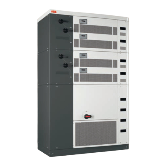
- Page 1 ® AURORA HOTOVOLTAIC NVERTERS USER MANUAL INSTALLATION and MAINTENANCE PVI-55.0-YY(-TL) Models*: PVI-110.0-YY(-TL) PVI-165.0-YY(-TL) PVI-220.0-YY(-TL) PVI-275.0-YY(-TL) PVI-330.0-YY(-TL) (*) “YY” indicates the country in which the product is on sale. (*) “TL” indicates the absence of the insulation Transformer on board. Rev. 1.0...
- Page 2 Installation and Operation Manual Page 2 of 156 [PVI-XXX.0-YY(-TL) - Rev:1.0] LEGEND DANGER Marks the reference to a paragraph Texts marked with this symbol indicate in a chapter containing important provisions which, if not met, could result in safety information and warnings death or serious injury to the person or which must always be respected.
- Page 3 [PVI-XXX.0-YY(-TL) - Rev:1.0] THANK YOU FOR YOUR TRUST The "AURORA" Power-One Inverter you have purchased is a device containing the latest technologies. Before using this device for the first time, read these user instructions in order to fully and quickly learn the commands and functions, as well as the potential dangers for you and for others, and how to avoid them.
- Page 4 A. Morucci 15-03-10 D.Nocentini First Issue S. Soldani A. Morucci Various Updates and Integration 06-05-10 D.Nocentini S. Soldani New Documents POWER-ONE: Complete or partial reproduction of this document by any means whatsoever is strictly forbidden without prior authorisation of Power-One.
-
Page 5: Table Of Contents
Installation and Operation Manual Page 5 of 156 [PVI-XXX.0-YY(-TL) - Rev:1.0] TABLE OF CONTENTS 1. HOW TO USE AND READ THE MANUAL ....................12 1.1. D ............................12 ISPOSAL OF WASTE 1.2. S ........................13 YMBOLS USED WITH THE PRODUCT 1.3. - Page 6 Installation and Operation Manual Page 6 of 156 [PVI-XXX.0-YY(-TL) - Rev:1.0] 7. PROTECTIONS ............................48 7.1. P ......................48 ROTECTION AGAINST MAINS BREAKDOWN 7.2. G (SPI) ......................48 RID INTERFACE PROTECTION DEVICE 7.3. A ..........................49 DDITIONAL PROTECTION 8. RS485 SERIAL LINE ..........................50 8.1.
- Page 7 Installation and Operation Manual Page 7 of 156 [PVI-XXX.0-YY(-TL) - Rev:1.0] 13. INTERACTIVE DISPLAY ........................... 92 13.1. H ........................92 OW THE DISPLAY FUNCTIONS 13.2. P ............................93 ASSWORD ENTRY 13.3. T LED ............................93 HE DISPLAY 13.4. F ) ....................95 UNCTIONAL DIAGRAM OF THE DISPLAY 13.5.
- Page 8 Installation and Operation Manual Page 8 of 156 [PVI-XXX.0-YY(-TL) - Rev:1.0] 15.4.12 Solar field scan ..........................120 15.4.12.1 Loading and visualisation of the P-V curves saved ..................124 15.4.12.2 Software Version ............................125 16. MAINTENANCE / REPAIRS ........................126 16.1. R ..........................
- Page 9 Installation and Operation Manual Page 9 of 156 [PVI-XXX.0-YY(-TL) - Rev:1.0] 20. ERROR MESSAGES AND CODES ......................145 20.1. W ..............................145 ARNING 20.2. E ..............................145 RROR 21. TECHNICAL DATA ..........................147 21.1. T ..........................147 ECHNICAL DATA TABLES 22.
- Page 10 Installation and Operation Manual Page 10 of 156 [PVI-XXX.0-YY(-TL) - Rev:1.0] 9-1: T ..........................57 IGURE RANSPORT CRATE 9-2: D ..............58 IGURE O NOT FORK UP FROM THE FRONT SIDE IF NOT REALLY NECESSARY 9-3: W ............................58 IGURE OODEN BASE 9-4: C ..................
- Page 11 Installation and Operation Manual Page 11 of 156 [PVI-XXX.0-YY(-TL) - Rev:1.0] 15-7: D ......................109 IGURE ISPLAY OF OLAR MONITORING 15-8: R – R ....................110 IGURE NTERFACE ANAGEMENT 15-9: I ID – S ..................... 112 IGURE NVERTER INGLE ODULE NTERFACE 15-10: I ........................
-
Page 12: How To Use And Read The Manual
Power-One shall not be liable for damages consequent to the use of inappropriate spare parts. Power-One reserves the right to make changes to this Manual and to the product without prior notice: the latest version of the Manual indicating the revision number will be available soon on the site (www.power-one.com). -
Page 13: Symbols Used With The Product
Installation and Operation Manual Page 13 of 156 [PVI-XXX.0-YY(-TL) - Rev:1.0] 1.2. Symbols used with the product The symbols referring to the electrical parts of the device and that may also be used in this Manual are the following: Connection point for earth conductor Continuous positive voltage pole Continuous negative voltage pole Direct current (VDC) -
Page 14: Documents Provided With The Device
Installation and Operation Manual Page 14 of 156 [PVI-XXX.0-YY(-TL) - Rev:1.0] Figure 1-2: Identification label Generic code “Part Number” Serial order Serial order total quantity Shipping configuration Serial Number Production date General description of the product 1.4. Documents provided with the device •... -
Page 15: Important Safety Information
Installation and Operation Manual Page 15 of 156 [PVI-XXX.0-YY(-TL) - Rev:1.0] 2. IMPORTANT SAFETY INFORMATION NOTICE WARNING The connection to the distribution grid The installation of the PVI-XXX.0(-TL) must should be made only after receiving be performed in compliance with national approval from the Body responsible for and local regulations. - Page 16 Installation and Operation Manual Page 16 of 156 [PVI-XXX.0-YY(-TL) - Rev:1.0] DANGER DANGER The personnel operating inside the PVI- It is extremely important and opportune to XXX.0(-TL), or removing the protections on disconnect inverter prior live parts, must wear suitable personal connection photovoltaic field...
-
Page 17: General Information
Power-One assumes no liability for damage to persons and property due to incorrect interpretation of the instructions in this Manual or from improper use of the device. -
Page 18: General Information And Features Of A Photovoltaic System
Installation and Operation Manual Page 18 of 156 [PVI-XXX.0-YY(-TL) - Rev:1.0] 3. GENERAL INFORMATION AND FEATURES OF A PHOTOVOLTAIC SYSTEM The purpose of this chapter is to provide the user of "AURORA PVI-XXX.0 (-TL)" general information concerning the photovoltaic systems that transform solar energy into electrical energy, usable in the distribution grid. -
Page 19: Fundamental Elements Of The Photovoltaic Field: "Strings" And "Arrays
Installation and Operation Manual Page 19 of 156 [PVI-XXX.0-YY(-TL) - Rev:1.0] 3.2. Fundamental elements of the photovoltaic field: “Strings” and “Arrays” In order to significantly reduce installation costs of the photovoltaic field, especially related to the wiring problem on the inverter DC side and the subsequent distribution on the AC side, the STRING technology was developed. - Page 20 On the Power-One website (www.power-one.com) a configuration program is available, that can help with the correct dimensioning of the photovoltaic system.
-
Page 21: Scope And General Description Of The Product
Installation and Operation Manual Page 21 of 156 [PVI-XXX.0-YY(-TL) - Rev:1.0] 4. SCOPE AND GENERAL DESCRIPTION OF THE PRODUCT Figure 4-1: PVI-XXX.0 Series (WITH TRANSFORMER) Figure 4-2: PVI-XXX.0-TL Series (WITHOUT TRANSFORMER) - Page 22 Installation and Operation Manual Page 22 of 156 [PVI-XXX.0-YY(-TL) - Rev:1.0] The PVI-XXX.0(-TL) (Figure 4-1 and Figure When used in parallel with the grid, the 4-2) are devices designed exclusively for inverter alternating current output flows converting solar energy into electricity through the insulation Transformer (where compatible with the grid of the country required) in the industrial distribution...
-
Page 23: Figure 4-3: Example Of Connection To The Ac Grid Of The Inverter With Transformer On Board
Installation and Operation Manual Page 23 of 156 [PVI-XXX.0-YY(-TL) - Rev:1.0] PVI-220.0 PHOTOVOLTAIC FIELD AC BREAKER LINE DC BREAKER Figure 4-3: Example of connection to the AC grid of the inverter with Transformer on board... -
Page 24: Figure 4-4: Example Of Connection To The Ac Grid Of The Inverter Without Transformer On Board
Installation and Operation Manual Page 24 of 156 [PVI-XXX.0-YY(-TL) - Rev:1.0] PHOTOVOLTAIC FIELD AC BREAKER MEDIUM VOLTAGE TRASFORMER MEDIUM VOLTAGE GRID DC BREAKER Figure 4-4: Example of connection to the AC grid of the inverter without Transformer on board... -
Page 25: Technical Description Of Aurora Pvi-Xxx.0(-Tl)
Installation and Operation Manual Page 25 of 156 [PVI-XXX.0-YY(-TL) - Rev:1.0] 4.1. Technical Description of AURORA PVI-XXX.0(-TL) Figure 4-5 shows the block diagram of AURORA PVI-220.0-YY. For models with low power (165kW, 110kW, 55kW), the block diagram is similar but with less number of 55kWp modules. -
Page 26: Figure 4-5: Electrical Diagram Of Maximum Pvi-Xxx.0
Installation and Operation Manual Page 26 of 156 [PVI-XXX.0-YY(-TL) - Rev:1.0] INVERTER MODULE 55kW Breaker DC Fuse Contact INVERTER LINE Fuse FILTER 55kW FILTER Solar Panel FILTER Connection INVERTER MODULE 55kW Breaker DC Fuse INVERTER LINE Contact Fuse FILTER 55kW FILTER Solar Panel FILTER... -
Page 27: Figure 4-6: Electrical Diagram Of Maximum Pvi-Xxx.0 With Transformer (Versions 275Kw And 330Kw)
Installation and Operation Manual Page 27 of 156 [PVI-XXX.0-YY(-TL) - Rev:1.0] Figure 4-6: Electrical diagram of maximum PVI-XXX.0 with Transformer (versions 275kW and 330kW) -
Page 28: Figure 4-7: Electrical Diagram Of Maximum Pvi-Xxx.0(-Tl) Without Transformer (For All Versions)
Installation and Operation Manual Page 28 of 156 [PVI-XXX.0-YY(-TL) - Rev:1.0] INVERTER MODULE 55kW Breaker DC Fuse INVERTER LINE Contact Fuse FILTER 55kW FILTER Solar Panel DC Connection FILTER INVERTER MODULE 55kW Breaker DC Fuse INVERTER LINE Contact Fuse FILTER 55kW FILTER Solar Panel... -
Page 29: Multi-Master
Installation and Operation Manual Page 29 of 156 [PVI-XXX.0-YY(-TL) - Rev:1.0] The block diagram of Figure 4-5 shows the 4.1.2 Multi-Master/Slave AURORA PVI-220.0 model with its 4 The Multi-Master/Slave mode, where the independent converters (Multi-Master Master/Slave Framework controls the mode). maximum power point tracker (MPPT), is possible only by properly configuring the DC The block diagram of Figure 4-6 shows the... -
Page 30: Mppt (Maximum Power Point Tracker)
Installation and Operation Manual Page 30 of 156 [PVI-XXX.0-YY(-TL) - Rev:1.0] On days with variable cloudiness, solar power changes occur very fast NOTICE and wide-ranging. These modes may be carried out by Variations between 100W/m² and configuring the entire device and each 1200 W/m²... -
Page 31: Special Features
Installation and Operation Manual Page 31 of 156 [PVI-XXX.0-YY(-TL) - Rev:1.0] The inverter is controlled in each module by a DSP (Digital Signal Processor) and by a central microprocessor. This means that the failure of a module does not compromise the whole system but only the loss of up to 55kWp. -
Page 32: Description Of Components And Composition Of The Pvi-Xxx.0(-Tl)
Installation and Operation Manual Page 32 of 156 [PVI-XXX.0-YY(-TL) - Rev:1.0] 5. DESCRIPTION OF COMPONENTS AND COMPOSITION OF THE PVI- XXX.0(-TL) 5.1. Overview Figure 5-1 shows the main components of the PVI-XXX.0 for versions 275kW and 330kW with the insulation Transformer. If a non-isolated device shall be required, only the main “Tower” will be present, without the “ACbox-Transformer”... -
Page 33: Figure 5-2: General Overview Of The Pvi-Xxx.0(-Tl) ( Versions Inferior To 220 K W)
Installation and Operation Manual Page 33 of 156 [PVI-XXX.0-YY(-TL) - Rev:1.0] For power versions equal to 165kW or 220kW, the device with the insulation Transformer is presented as in Figure 5-2(l.h.), while the device without Transformer is like in Figure 5-2(r.h.). As can see in the figure we have two Frameworks (E) each containing three or four 55kW modules. -
Page 34: Description Of The Inverter Parts
Installation and Operation Manual Page 34 of 156 [PVI-XXX.0-YY(-TL) - Rev:1.0] 5.2. Description of the inverter parts Figure 5-3: General view of ACBOX (A) (versions with Transformer ≤220kW) Figure 5-4: General view of ACBOX (A) (versions with power ≥275kW or without Transformer) -
Page 35: Acbox (A)
Installation and Operation Manual Page 35 of 156 [PVI-XXX.0-YY(-TL) - Rev:1.0] The insulation Transformer (with frontal 5.2.1 ACBOX (A) view) remains on the back side of the 5.2.1.1 Version until 220kW with "ACBOX". Transformer The cooling system consisting of four fans for models 220kW and 165kW (with frontal The connection area of the DC cables from view) remains in the rear above the... -
Page 36: Figure 5-7: Ac Auxiliary Voltage Input ( Versions With Transformer ≤220 K W)
Installation and Operation Manual Page 36 of 156 [PVI-XXX.0-YY(-TL) - Rev:1.0] The auxiliary AC power input is located on The terminal block for serial communication the right bottom of the "ACBOX". links and various signals (frontal view) is located on the right top side of the "ACBOX". -
Page 37: Version ≥275Kw And All Models Without Insulation Transformer
Installation and Operation Manual Page 37 of 156 [PVI-XXX.0-YY(-TL) - Rev:1.0] 5.2.1.2 Version ≥275kW and all models without insulation Transformer For the models with Transformer, the “ACBOX” area Figure 5-1(A) is divided in two parts. The part containing the Transformer “ACbox-Transformer”... -
Page 38: Figure 5-12: Signal Input/Output (Versions With Power ≥275Kw Or Without Transformer)
Installation and Operation Manual Page 38 of 156 [PVI-XXX.0-YY(-TL) - Rev:1.0] In the central part (Figure 5-12) is located: the auxiliary AC power input and the relative switch, an electrical socket, a protection module against overvoltages for the serial line, the terminal block with the connections for the serial communication and other signals. -
Page 39: Dc Box (B)
Installation and Operation Manual Page 39 of 156 [PVI-XXX.0-YY(-TL) - Rev:1.0] 5.2.2 DC Box (B) 5.2.5 Framework (E) On the external front panel are fixed the This group, called Framework, contains the handles of the DC switches. The panel is B, C and D areas and it may be complete removable and allows access to the fuse box (100kW... -
Page 40: Description Of The Input Configurations And Dc Switches Operation
Installation and Operation Manual Page 40 of 156 [PVI-XXX.0-YY(-TL) - Rev:1.0] 6. DESCRIPTION OF THE INPUT CONFIGURATIONS AND DC SWITCHES OPERATION 6.1. Possible field configurations There various ways 6.1.1 Multi-Master configuring the AURORA PVI-XXX.0(- In this configuration the inverter behaves as TL) input in order to meet the many separate inverters with 55kW power, construction requirements of the... -
Page 41: Multi-Master-Slave
Installation and Operation Manual Page 41 of 156 [PVI-XXX.0-YY(-TL) - Rev:1.0] Figure 6-3: PVI-330.0(-TL) Composition Figure 6-2: PVI-220.0 Composition (Multi-Master-Slave) (Multi-Master) 6.1.2 Multi-Master-Slave In this configuration the inverter behaves as many separate inverters with 110kW power, half of the number of modules present in the "Tower"... -
Page 42: Master-Slave With A Single Master
Installation and Operation Manual Page 42 of 156 [PVI-XXX.0-YY(-TL) - Rev:1.0] The position of the “Master” in the Framework is not default. The module with the highest serial number is always the master. 6.1.3 Master-Slave with a single Master It is also possible to use the inverter, with sizes equal to 165kW or higher, in Master- Slave version with only one Master. -
Page 43: Features Of The External Dc Switch
Installation and Operation Manual Page 43 of 156 [PVI-XXX.0-YY(-TL) - Rev:1.0] • It is recommended the sole function of the 6.1.3.1 Features of the external DC switch. Given the limited nature of the field switch current it is preferable not to use breakers It is important to choose the external DC with solenoid switches. -
Page 44: Function Of The Dc Disconnecting Switches In Every Framework
Installation and Operation Manual Page 44 of 156 [PVI-XXX.0-YY(-TL) - Rev:1.0] 6.2. Function of the DC disconnecting switches in every Framework Inside the side panel, the switch on the lower right side acts on the connection of the low module (L-Low), while the switch on the top right acts on the high module (H-High). -
Page 45: Multi-Master System
Installation and Operation Manual Page 45 of 156 [PVI-XXX.0-YY(-TL) - Rev:1.0] 6.2.1 Multi-Master System In this configuration there is no physical link between the photovoltaic fields in each module. Each DC disconnecting switch is practically independent of the others. The following table indicates, in the first column, the position of the switches, in the second whether the photovoltaic field is connected to the module, and in the third whether it can be removed or inserted in the seat. -
Page 46: Multi-Master-Slave System
Installation and Operation Manual Page 46 of 156 [PVI-XXX.0-YY(-TL) - Rev:1.0] 6.2.2 Multi-Master-Slave System In this configuration, the two modules of the Master-Slave Framework have the same photovoltaic field. Each DC disconnecting switch is linked to the other of the same Framework. NOTICE In this case, it is particularly important to understand the use of the DC disconnecting... -
Page 47: Master-N.slave System 1 (With Inverter ≥ 165Kw)
Installation and Operation Manual Page 47 of 156 [PVI-XXX.0-YY(-TL) - Rev:1.0] 6.2.3 Master-N.Slave System 1 (with inverter ≥ 165kW) In this configuration, all modules have the same photovoltaic field. Each DC disconnecting switch is linked to the others and to the other Frameworks. NOTICE In this case, it is particularly important to understand the use of the DC disconnecting... -
Page 48: Protections
Installation and Operation Manual Page 48 of 156 [PVI-XXX.0-YY(-TL) - Rev:1.0] 7. PROTECTIONS 7.1. Protection against mains breakdown In case of an interruption of the local avoid possible island operations, distribution grid from electricity AURORA is provided with an automatic company or if the apparatus is switched off protective disconnection system. -
Page 49: Additional Protection
Installation and Operation Manual Page 49 of 156 [PVI-XXX.0-YY(-TL) - Rev:1.0] 7.3. Additional protection AURORA equipped with additional Protection fuses: protections to guarantee the safe operation • DC side: presence or not of the fuses, under any circumstances. Such protections configuration according to the input include:... -
Page 50: Rs485 Serial Line
Installation and Operation Manual Page 50 of 156 [PVI-XXX.0-YY(-TL) - Rev:1.0] 8. RS485 SERIAL LINE 8.1. Connection modalities of the RS485 line The connection for communication with the exterior of the PVI-XXX.0(-TL) occurs by The use of a computer is not means of the RS485 data serial line. -
Page 51: Figure 8-1: Passage Mode Of The Pvi-Xxx.0
Installation and Operation Manual Page 51 of 156 [PVI-XXX.0-YY(-TL) - Rev:1.0] Figure 8-1: Passage mode of the PVI-XXX.0 serial cable Figure 8-2: Passage mode of the PVI-XXX.0-TL serial cable PVI-XXX.0(-TL) of various types may be connected in “daisy-chain”. It is possible to connect devices of different types and sizes. -
Page 52: Figure 8-3: Type Of Connection Of The Pvi-Xxx.0(-Tl)
Installation and Operation Manual Page 52 of 156 [PVI-XXX.0-YY(-TL) - Rev:1.0] Figure 8-3: Type of connection of the PVI- Figure 8-4: Type of connection of the PVI- XXX.0(-TL) XXX.0(-TL) -
Page 53: Connection Modes For Monitoring
Installation and Operation Manual Page 53 of 156 [PVI-XXX.0-YY(-TL) - Rev:1.0] 8.2. Connection modes for monitoring There are 2 main modes (A and B) to connect the RS485 line from the PVI-XXX.0(-TL), in order to carry out the monitoring of the inverter, while a third mode (C) does not require the RS485 connection. - Page 54 Installation and Operation Manual Page 54 of 156 [PVI-XXX.0-YY(-TL) - Rev:1.0] Where: Connection to the PVI-XXX.0(-TL) with a PC. The Computer is connected to the RS485 of the inverter by means of the Aurora RS232/485 Converter adapter. The PC must have the monitoring software installed for the PVI-XXX.0(-TL).
-
Page 55: Storage And Handling
Installation and Operation Manual Page 55 of 156 [PVI-XXX.0-YY(-TL) - Rev:1.0] 9. STORAGE AND HANDLING 9.1. Preliminary checks The dealer has safely delivered your AURORA to the forwarding agent, and in NOTICE perfect condition. The forwarding agent, by accepting package, assumes It is important, before installation, to check responsibility until delivery. -
Page 56: Handling And Withdrawal Of The Pvi-Xxx.0(-Tl) From The Packaging
Installation and Operation Manual Page 56 of 156 [PVI-XXX.0-YY(-TL) - Rev:1.0] • • If the inspection reveals damages, call the It is the customer's responsibility to make a dealer or the authorised dealer. He will complaint with the forwarding agent. Failure decide whether the equipment should be to follow this procedure can lead to the loss returned for repair and provide instructions... -
Page 57: Removal Of The Inverter From The Wooden Crate
Installation and Operation Manual Page 57 of 156 [PVI-XXX.0-YY(-TL) - Rev:1.0] 9.2.2 Removal of the inverter from the wooden crate NOTICE The packaging of the PVI-XXX.0(-TL) is done as in Figure 9-1. To withdraw the inverter it is necessary to remove the lid first, and then the side panel corresponding to the rear side of the inverter, which can be identified by the wording “fork up from this side”. -
Page 58: Figure 9-2: Do Not Fork Up From The Front Side If Not Really Necessary
Installation and Operation Manual Page 58 of 156 [PVI-XXX.0-YY(-TL) - Rev:1.0] Figure 9-2: Do not fork up from the front side if not really necessary Considering the particular type of the front After removing the rear part of the side of the PVI-XXX.0(-TL), you should not packaging, the wooden base must be use this side for regular handling operations, removed in order to withdraw the PVI-... -
Page 59: Handling Of The Pvi-Xxx.0 (-Tl)
Installation and Operation Manual Page 59 of 156 [PVI-XXX.0-YY(-TL) - Rev:1.0] 9.2.3 Handling of the PVI-XXX.0 The mechanical parts that will complete the (-TL) base are packaged separately and placed on the top of the inverter (Figure 9-4). These After opening the crate, the inverter may be should be mounted after the device and withdrawn. -
Page 60: Figure 9-5: Not Allowed Handling
Installation and Operation Manual Page 60 of 156 [PVI-XXX.0-YY(-TL) - Rev:1.0] HIGH CENTRE OF GRAVITY! Figure 9-5: Not allowed handling... -
Page 61: Figure 9-6: Allowed Handling
Installation and Operation Manual Page 61 of 156 [PVI-XXX.0-YY(-TL) - Rev:1.0] WARNING MAKE ONLY ESSENTIAL MOVES SLIGHTLY LIFT EXPAND FORKS Figure 9-6: Allowed handling... -
Page 62: Installation
Installation and Operation Manual Page 62 of 156 [PVI-XXX.0-YY(-TL) - Rev:1.0] 10. INSTALLATION DANGER The electrical installation of the PVI-XXX.0(-TL) must be carried out in compliance with the applicable local and national laws. All cables used and connected to the device or under field voltage, must comply with the minimum insulation requirements of 1000Vdc. -
Page 63: Positioning In The Chosen Place
Installation and Operation Manual Page 63 of 156 [PVI-XXX.0-YY(-TL) - Rev:1.0] The hardware maintenance of the is carried out mainly from the front NOTICE (either the modules area or the AC BOX area (Figure 5-1 and Figure 5-2). However, it is good practice to allow In the design phase of the plant, take into access on all sides in order to consideration... -
Page 64: Figure 10-1: Footprint Of The Base
Installation and Operation Manual Page 64 of 156 [PVI-XXX.0-YY(-TL) - Rev:1.0] Figure 10-1: Footprint of the base (similar for all systems) INPUT/OUTPUT AUXILIARY AC INPUT DC CABLE INPUT AC CABLE CABLE AND SIGNAL CABLE Figure 10-2: Cable passage holes for systems with Transformer ≤220kW... -
Page 65: Figure 10-3: Cable Passage Holes For Figure 10-4: Ac Cable Passage For
Installation and Operation Manual Page 65 of 156 [PVI-XXX.0-YY(-TL) - Rev:1.0] Figure 10-3: Cable passage holes for ≥275kW systems and all models without Transformer INPUT AC CABLE INPUT AC CABLE 300VAC 400VAC Figure 10-4: AC cable passage for ≥275Kw systems “ACbox-Transformer”... -
Page 66: Air Vents
Installation and Operation Manual Page 66 of 156 [PVI-XXX.0-YY(-TL) - Rev:1.0] 10.2.1 Air vents Each framework has a grilled opening at the back to allow the outflow of hot air, as shown in Figure 10-5, or, for versions up to 110kW, it has a grilled fan on the top as shown in Figure 10-6. Every grill has 6 threaded anchorage points, as indicated. -
Page 67: Figure 10-6: Hot Air Outlet Fan For Versions Up To
Installation and Operation Manual Page 67 of 156 [PVI-XXX.0-YY(-TL) - Rev:1.0] Figure 10-6: Hot air outlet fan for versions up to 110kW... -
Page 68: Safety Distance
Installation and Operation Manual Page 68 of 156 [PVI-XXX.0-YY(-TL) - Rev:1.0] 10.2.2 Safety distance The following figure shows the minimum recommended distances to be observed: Figure 10-7: Safety distance Table 10-1: Table of recommended distances* 400mm 300mm 800mm 165mm (with air conduct) 400mm 300mm 800mm... -
Page 69: Figure 10-8: Example Of Installation
Installation and Operation Manual Page 69 of 156 [PVI-XXX.0-YY(-TL) - Rev:1.0] Figure 10-8: Example of installation The example above shows a cabin with the following points: • Air entry grill / filter • 1 PVI-220.0 • 1 PVI-330.0 • Simulation of the withdrawal of the 55kWp module •... -
Page 70: Removal Of Panels To Make The Connections
Installation and Operation Manual Page 70 of 156 [PVI-XXX.0-YY(-TL) - Rev:1.0] 10.2.3 Removal of panels to make the connections Remove the panels indicated below. Front lower panel (Figure 5-1, Figure 5-2: A) allows to access the AC connections for the connection to the distribution grid at 400Vac or 300Vac , to the 3P+N (400Vac) voltage connection that... -
Page 71: Composition Of The Acbox Area
Installation and Operation Manual Page 71 of 156 [PVI-XXX.0-YY(-TL) - Rev:1.0] 10.2.4 Composition of the ACBOX area After removing the front panel, the following area can be identified: Figure 10-11: Composition of the ACBOX Area (versions with power ≥275kW or without Transformer) Where: (1) DC cable connection area... -
Page 72: Figure 10-12: C
Installation and Operation Manual Page 72 of 156 [PVI-XXX.0-YY(-TL) - Rev:1.0] Figure 10-12: Cable output under the inverter (versions ≥275kW) RS485 Vac AUX Figure 10-13: Cable output under the inverter (versions without Transformer) -
Page 73: Figure 10-14: C
Installation and Operation Manual Page 73 of 156 [PVI-XXX.0-YY(-TL) - Rev:1.0] Figure 10-14: Cable output under the inverter (versions ≤200kW) -
Page 74: Electrical Connection
Installation and Operation Manual Page 74 of 156 [PVI-XXX.0-YY(-TL) - Rev:1.0] 11. ELECTRICAL CONNECTION DANGER Before handling any cable, make sure, using suitable instruments, that there is no dangerous voltage. WARNING The connection of AURORA to the electrical grid must be carried out only by qualified operators and only after having received authorisation from the electricity company that administrates the mains. -
Page 75: Connection Of The Dc Cables From The Photovoltaic Field
Installation and Operation Manual Page 75 of 156 [PVI-XXX.0-YY(-TL) - Rev:1.0] 11.2. Connection of the DC cables from the photovoltaic field After having carefully read and understood Follow the directions in the points and of the premises of the preceding paragraphs, the following figures: the cables from the photovoltaic field can be Locate the DC cables from the... -
Page 76: Figure 11-2: Dc Cable Connection
Installation and Operation Manual Page 76 of 156 [PVI-XXX.0-YY(-TL) - Rev:1.0] Figure 11-2: DC cable connection (versions ≤220kW with Transformer) After the cable passage it is important to make sure that the open grill holes are closed, e.g. by means of expanded foam. This operation guarantees that no animals or dust can get inside. -
Page 77: Connection Of The Protection Earth Cable (Pe)
Installation and Operation Manual Page 77 of 156 [PVI-XXX.0-YY(-TL) - Rev:1.0] 11.3. Connection of the protection earth cable (PE) WARNING For the safety of the PV plant the grounding resistance of the plant itself, is determinant. The latter must be established before the first start up of the Plant (In Table 11-2 are reported minimal... -
Page 78: Connection Of The Ac Power Cables
Installation and Operation Manual Page 78 of 156 [PVI-XXX.0-YY(-TL) - Rev:1.0] 11.4. Connection of the AC power cables Remove, present, front protection plastic cover placed in front of the bars, by means of the anchorage screws. Connect the AC power cables as indicated in Figure 11-5 or Figure 11-6. -
Page 79: Connection Of Auxiliary Energy Supply
Installation and Operation Manual Page 79 of 156 [PVI-XXX.0-YY(-TL) - Rev:1.0] 11.5. Connection of auxiliary energy supply Connect the five-pole cable (3P+N+T) to the clamps indicated in Figure 11-8 and Figure 11-7. NOTICE Pay maximum attention to the connection of the neutral cable! Lack of the neutral connection (blue clamp) or its inversion with one of the three phases may cause the Figure 11-7: Clamps for connecting the... -
Page 80: Connection Of The Twilight Sensor (Only For Pvi-Xxx.0 ≤220Kw)
Installation and Operation Manual Page 80 of 156 [PVI-XXX.0-YY(-TL) - Rev:1.0] 11.6. Connection of the Twilight Sensor (only for PVI-XXX.0 ≤220kW) Each PVI-XXX.0, equipped with twilight, comes with the light sensor to be installed (Figure 11-10). If the sensor is not installed and configured inverter cannot... -
Page 81: Connections For Communications / State Signals
Installation and Operation Manual Page 81 of 156 [PVI-XXX.0-YY(-TL) - Rev:1.0] 11.7. Connections for communications / state signals Figure 11-11: Internal terminal block ACBOX area Get a flat screwdriver of the correct The X20 and X27 clamps are dedicated to size for the clamp screws (with a tip of the communication connection (Table 11-2). -
Page 82: Connection For The User Rs485 Serial Communication
Installation and Operation Manual Page 82 of 156 [PVI-XXX.0-YY(-TL) - Rev:1.0] The following tables show the signals 11.7.1 Connection for the user present on the terminal board: RS485 serial communication Table 11-2: Communication signals in the Proceed with the connection of the RS485 terminal block serial line. -
Page 83: Setting Of The 120 Ohm Termination Of Rs485
Installation and Operation Manual Page 83 of 156 [PVI-XXX.0-YY(-TL) - Rev:1.0] 11.7.2 Setting of the 120 ohm termination of RS485 Each PVI-XXX.0(-TL) leaves the factory without the 120ohm termination of the RS485 communication line already set disabled. Figure 11-12 and Figure 11-13 illustrates the three mechanical configurations which show the presence of a card inside every framework and the dip-switch relative to the termination. - Page 84 Installation and Operation Manual Page 84 of 156 [PVI-XXX.0-YY(-TL) - Rev:1.0] Figure 11-13: Switch position of the 120 ohm termination...
-
Page 85: Connection For The Rs485 Serial Communication With Pvi-Stringcomb(-S)
Installation and Operation Manual Page 85 of 156 [PVI-XXX.0-YY(-TL) - Rev:1.0] This contact, in sleep mode, is connected 11.7.3 Connection for the RS485 internally, as illustrated in Figure 11-14. serial communication with PVI- Where n indicates the number of the 55kWp STRINGCOMB(-S) box, according to the numeration indicated in Figure 5-1, Figure 5-2. -
Page 86: Connection For The On And Off Command Of The Single 55Kwp Modules
Installation and Operation Manual Page 86 of 156 [PVI-XXX.0-YY(-TL) - Rev:1.0] 11.7.5 Connection for the on and 11.7.6 Setting of the off command of the single 55kWp communication addresses. modules. Put the QS2 switch in ON position (up): if the auxiliary line is under voltage, all With reference to Table Figure 11-11 and the present displays will be turned on. -
Page 87: Start Up (Service)
Installation and Operation Manual Page 87 of 156 [PVI-XXX.0-YY(-TL) - Rev:1.0] 12. START UP (SERVICE) Before starting up the system, make sure that all connections have been made correctly and, in general, that all safety conditions have been complied with. In particular, make sure that all voltage values are within the set limits. -
Page 88: Sequence For Commissioning (Not Valid For 1Master/N.slave Systems)
Installation and Operation Manual Page 88 of 156 [PVI-XXX.0-YY(-TL) - Rev:1.0] 12.2. Sequence for commissioning (NOT valid for 1Master/N.Slave systems) The procedure for starting up AURORA is the One at a time, close the DC switches in following: position 1 (Figure 6-8D): The display of the module relative to Make sure that the grid switch is on 0 the closed switch will signal the alarm... - Page 89 Installation and Operation Manual Page 89 of 156 [PVI-XXX.0-YY(-TL) - Rev:1.0] If the primary conditions (presence of At this point, the Master or Masters DC and AC voltage) are satisfied, the will show the power sent to the grid system will automatically connect to other parameters.
-
Page 90: Sequence For Commissioning The 1Master/N.slave Systems (Inverter ≥165Kw)
Installation and Operation Manual Page 90 of 156 [PVI-XXX.0-YY(-TL) - Rev:1.0] 12.3. Sequence for commissioning the 1Master/N.Slave systems (Inverter ≥165kW) The procedure for commissioning AURORA After closing all DC switches, close the in a 1 Master / n Slave system is the external DC disconnecting switch: following: The display of the modules will signal... - Page 91 Installation and Operation Manual Page 91 of 156 [PVI-XXX.0-YY(-TL) - Rev:1.0] If the primary conditions (presence of At this point, the Master or Masters DC and AC voltage) are satisfied, the will show the power sent to the grid system will automatically connect to other parameters.
-
Page 92: Interactive Display
Installation and Operation Manual Page 92 of 156 [PVI-XXX.0-YY(-TL) - Rev:1.0] 13. INTERACTIVE DISPLAY 13.1. How the display functions Figure 13-1: Display of the 55kWp module The two-line LCD display (Figure 13-1) is Scrolling can be blocked by pressing the ENTER key. The padlock symbol located on the front panel of each 55kWp module shows... -
Page 93: Password Entry
Installation and Operation Manual Page 93 of 156 [PVI-XXX.0-YY(-TL) - Rev:1.0] 13.2. Password entry • If a password is requested, carry out the By pressing ESC several times you will following procedure: return to the previous menus. • DOWN scrolls downwards through the The default password is 0000. -
Page 94: Table 13-1: Meaning Of The Display Leds
Installation and Operation Manual Page 94 of 156 [PVI-XXX.0-YY(-TL) - Rev:1.0] The following table shows the 5 configurations which can be indicated during the operation: Table 13-1: Meaning of the display LEDs STATE OF LEDs MEANING • All the LEDS are off. •... -
Page 95: Functional Diagram Of The Display (Menu)
Installation and Operation Manual Page 95 of 156 [PVI-XXX.0-YY(-TL) - Rev:1.0] 13.4. Functional diagram of the display (Menu) Figure 13-2: Functional diagram of the display (Main Menu) -
Page 96: Figure 13-3: Functional Diagram Of The Display
Installation and Operation Manual Page 96 of 156 [PVI-XXX.0-YY(-TL) - Rev:1.0] The Figure 13-2 shows the information displayed during normal operation. By pressing ENTER, ESC, UP or DOWN, you can scroll among menus as indicated. Impostazioni Inserimento Indirizzo indirizzo External 485s Selezione della Baud rate... -
Page 97: Figure 13-4: Functional Diagram Of The Display
Installation and Operation Manual Page 97 of 156 [PVI-XXX.0-YY(-TL) - Rev:1.0] Informazioni ID modulo N° serie modulo ID sistema N° serie sys. Trafo Type Firmware Junction Box N: n T: n R: n J1 P: x Monitor Jbox J2 P: x N. -
Page 98: Figure 13-5: Functional Diagram Of The Display
Installation and Operation Manual Page 98 of 156 [PVI-XXX.0-YY(-TL) - Rev:1.0] Figure 13-5: Functional diagram of the display (Statistics menu) -
Page 99: Information
Installation and Operation Manual Page 99 of 156 [PVI-XXX.0-YY(-TL) - Rev:1.0] 13.5. Information By selecting the INFORMATION menu, the 13.5.5 Trafo type display will show a submenu as shown in By selecting “Trafo type”, the following Figure 13-4. information will be shown: •... -
Page 100: States
Installation and Operation Manual Page 100 of 156 [PVI-XXX.0-YY(-TL) - Rev:1.0] 13.5.7.1 States 13.5.7.2 Fuses This item of the menu allows for verification This item of the menu allows for verification of the state of all the parameters of the of the state of the single fuses of the StringCombs selected previously. -
Page 101: Partial
Installation and Operation Manual Page 101 of 156 [PVI-XXX.0-YY(-TL) - Rev:1.0] 13.6.4 Partial 13.6.7 E-Month selecting “Partial”, following By selecting “E-Month”, the following information will be shown: information will be shown: • • PT: Total operating time since the last E: Total energy produced this month. -
Page 102: Before Using The Software
Installation and Operation Manual Page 102 of 156 [PVI-XXX.0-YY(-TL) - Rev:1.0] 14. BEFORE USING THE SOFTWARE The software produced for the PVI-XXX.0(- Since, as already described, the TL) allows for setting the transmission serial transmission standard of the parameters (e.g. baud rate) and for control PVI-XXX.0(-TL) is the RS485, while (e.g. -
Page 103: Monitoring And Configuration Interface
Installation and Operation Manual Page 103 of 156 [PVI-XXX.0-YY(-TL) - Rev:1.0] 15. MONITORING AND CONFIGURATION INTERFACE 15.1. Conventions used In this chapter the following conventions are 15.1.1 Rack and Modules used in the text: Hereinafter, the single 55kWp boxes will be •... -
Page 104: Diagram Of The Monitoring Software
Installation and Operation Manual Page 104 of 156 [PVI-XXX.0-YY(-TL) - Rev:1.0] 15.3. Diagram of the monitoring software The following “map” simplifies the learning of the monitoring program structure. The next paragraphs will describe in detail the single blocks of the diagram. Single Plant Selezione... -
Page 105: Use Of The Monitoring Program
Installation and Operation Manual Page 105 of 156 [PVI-XXX.0-YY(-TL) - Rev:1.0] 15.4. Use of the monitoring program Click twice on the icon of the “Aurora Central CVI” program and wait for the following window to appear: Figure 15-2: Choice of the interface type Choose the type of visualisation through (Interface Mode): •... -
Page 106: Single Module Panel
Installation and Operation Manual Page 106 of 156 [PVI-XXX.0-YY(-TL) - Rev:1.0] For the “advanced” mode it is Based on the choice done before, the necessary to insert the password Single Module Panel (Figure 15-4) or “aurora”. In "standard" mode, some Plant Configuration window... -
Page 107: Plant Configuration
Installation and Operation Manual Page 107 of 156 [PVI-XXX.0-YY(-TL) - Rev:1.0] 15.4.2 Plant Configuration At first this window will be empty. This is because the first time the program has to scan to see how the plant is configured. PLANT VALUE RACK SN MODULE SN... -
Page 108: Figure 15-6: Choice Of Thes
Installation and Operation Manual Page 108 of 156 [PVI-XXX.0-YY(-TL) - Rev:1.0] Figure 15-6: Choice of the StringComb Manager By double-clicking on the tower image From the Display menu, it is possible to you can access the rack management open a system monitoring page that is menu (Figure 15-11) in which it is very useful to create a small monitoring possible to control and identify an... -
Page 109: Figure 15-7: Display Of Solar Monitoring
Installation and Operation Manual Page 109 of 156 [PVI-XXX.0-YY(-TL) - Rev:1.0] Figure 15-7: Display of Solar monitoring... -
Page 110: Rack Interface
Installation and Operation Manual Page 110 of 156 [PVI-XXX.0-YY(-TL) - Rev:1.0] 15.4.3 Rack Interface Figure 15-8: Rack Interface – Rack Management In this mode, the main parameters and the Figure Figure 15-8 shows the content of the state of every module of the system can be list where the following sizes can be seen: observed: Voltage [Panel]: Voltage read by the... -
Page 111: Menus Bar
Installation and Operation Manual Page 111 of 156 [PVI-XXX.0-YY(-TL) - Rev:1.0] Aux Temp 2: N/A (the data visualised is not 15.4.4 Menus bar used) Aux Temp 3: Framework environment temp. From the standard or advanced mode, you sensor [°C] may access the following menus: Energy (today): Energy produced today Menus in Standard mode [kWh]... -
Page 112: Inverter Identification
Installation and Operation Manual Page 112 of 156 [PVI-XXX.0-YY(-TL) - Rev:1.0] 15.4.5 Inverter Identification The window which summarises the plate data of a single module is the following: Figure 15-9: Inverter ID – Single Module Interface The parameters listed are the following: SN: Series number of the module PN: Part number of the module Week: Week of production... -
Page 113: Inverter Monitoring
Installation and Operation Manual Page 113 of 156 [PVI-XXX.0-YY(-TL) - Rev:1.0] 15.4.6 Inverter Monitoring This window allows for monitoring a single module on the rack side. Figure 15-10: Inverter Monitoring • • DC Side: in this area, the DC electrical Side: indicates voltages,... -
Page 114: Rack Monitoring
Installation and Operation Manual Page 114 of 156 [PVI-XXX.0-YY(-TL) - Rev:1.0] 15.4.7 Rack Monitoring This window allows for monitoring all modules that are part of the rack. Figure 15-11: Rack Monitoring • • DC Side: in this area, the DC electrical Fans: shows the rotation speed of the dimensions are collected. -
Page 115: Fault Log
Installation and Operation Manual Page 115 of 156 [PVI-XXX.0-YY(-TL) - Rev:1.0] 15.4.8 Fault Log This window lists the faults/alarms registered by the selected module: Figure 15-12: Window for saving the fault list The (Date/Hour format) box allows to specify the format of the date on which the data will be visualised. -
Page 116: Figure 15-14: Fault Log
Installation and Operation Manual Page 116 of 156 [PVI-XXX.0-YY(-TL) - Rev:1.0] Figure 15-14: Fault log The following information is given in the fault log column: Fault num: Progressive line number. Fault code: Code assigned to the fault. Fault label: Label describing the fault. Date/hour: Date and time when the fault occurred. -
Page 117: Statistic Field Reset
Installation and Operation Manual Page 117 of 156 [PVI-XXX.0-YY(-TL) - Rev:1.0] 15.4.9 Statistic Field Reset This window allows for cancellation of the energy statistics values. Confirmation of the reset operation will be requested. Choose [YES] or [NO]: Figure 15-15: Eeprom Reset By clicking on the [Stats EEprom Value If you choose [YES] a wait window will RESET] the following warning window... -
Page 118: Inverter Clock Settings
Installation and Operation Manual Page 118 of 156 [PVI-XXX.0-YY(-TL) - Rev:1.0] 15.4.10 Inverter clock settings This function allows for the system clock to be set. If the time is changed on a Slave module, the system warns that the modification will only affect that module. -
Page 119: String Comb Monitoring
Installation and Operation Manual Page 119 of 156 [PVI-XXX.0-YY(-TL) - Rev:1.0] 15.4.11 String Comb monitoring If the system has the string boxes (StringComb), this window will allow for the parameters of this apparatus to be monitored. Figure 15-17: StringComb monitoring To use this program, please consult the manual of the PVI-STRINGCOMB(-S): “B OXES FOR THE ”... -
Page 120: Solar Field Scan
Installation and Operation Manual Page 120 of 156 [PVI-XXX.0-YY(-TL) - Rev:1.0] 15.4.12 Solar field scan This function allows for scanning the photovoltaic field and gives the P-V curve of the field. The following window is composed mainly of a blank area where the features detected in the field will be "drawn": •... - Page 121 Installation and Operation Manual Page 121 of 156 [PVI-XXX.0-YY(-TL) - Rev:1.0] If known, write the radiation and temperature values in the special boxes (this operation can also be omitted). Press the [Start Scan] button. The program asks whether the operator wishes to visualise the master curve ([Master Only] button) or the master with the slaves ([Master + Slave]button), requesting a name for the curve.
- Page 122 Installation and Operation Manual Page 122 of 156 [PVI-XXX.0-YY(-TL) - Rev:1.0] After the scan, the program asks for a name to be assigned to the data file.
-
Page 123: Figure 15-18: Solar Field Scan
Installation and Operation Manual Page 123 of 156 [PVI-XXX.0-YY(-TL) - Rev:1.0] Enter a name and press [OK]. After the file has been saved, the curve is drawn (Figure 15-18) Figure 15-18: Solar Field Scan In the area indicated by the dotted line at the top, the values of exported power and voltage are visualised, as well as the maximum points reached by the curve. -
Page 124: Loading And Visualisation Of The P-V Curves Saved
Installation and Operation Manual Page 124 of 156 [PVI-XXX.0-YY(-TL) - Rev:1.0] 15.4.12.1 Loading and visualisation of the P-V curves saved This function allows the P-V characteristics found to be saved in a file. In this way, an archive of the characteristics of the photovoltaic field will be created. -
Page 125: Software Version
Installation and Operation Manual Page 125 of 156 [PVI-XXX.0-YY(-TL) - Rev:1.0] 15.4.12.2 Software Version The window shows only the version of the software is being used. Press the button to close the panel and return to the previous screen. -
Page 126: Maintenance / Repairs
Installation and Operation Manual Page 126 of 156 [PVI-XXX.0-YY(-TL) - Rev:1.0] 16. MAINTENANCE / REPAIRS This chapter describes the operations The equipment is designed to necessary to disconnect the device in order provide a lifetime operation of not to carry out internal repairs in safety less than five... -
Page 127: Routine Maintenance
Installation and Operation Manual Page 127 of 156 [PVI-XXX.0-YY(-TL) - Rev:1.0] 16.1. Routine maintenance Maintenance inside the PVI-XXX.0(-TL) must be carried out following the procedures shown in Table 16-1. Table 16-1: TABLE OF ROUTINE MAINTENANCE ACTIVITY FREQUENCY* PAR. Cleaning of filters and grills and internal inspection for dirt Every six §16.1.1 and/or water... -
Page 128: Acbox Area Filter
Installation and Operation Manual Page 128 of 156 [PVI-XXX.0-YY(-TL) - Rev:1.0] After removing the panel, the filter fitted 16.1.1.2 ACBOX area filter onto the internal side can be removed (Figure 16-2) and washed (do not use WARNING solvents!). Also clean the panel grills if necessary. -
Page 129: Visual And Screw Inspections
Installation and Operation Manual Page 129 of 156 [PVI-XXX.0-YY(-TL) - Rev:1.0] NOTICE NOTE: Before replacing the filter, make sure that it is perfectly dry and turn the knob of the power switch to 0. If no further checks are necessary, replace the panel. -
Page 130: Figure 16-5: Panels To Be Removed To Acces Dc And Ac Fuses
Installation and Operation Manual Page 130 of 156 [PVI-XXX.0-YY(-TL) - Rev:1.0] Once the system has been disconnected and the inverter panels have been removed Figure 10-9 and Figure 16-5, in this case remove if necessary also panels on the other sides), check as indicated in the Table 16-2 Figure 16-5: Panels to be removed to acces DC and AC Fuses. -
Page 131: Checks Of The Acbox Area
Installation and Operation Manual Page 131 of 156 [PVI-XXX.0-YY(-TL) - Rev:1.0] Turn the knob of the thermostat 16.1.3 Checks of the ACBOX area temperature completely counter- The following checks regard the cooling clockwise (the QS2 switch must be ON). system protection devices In this position of the thermostat the... -
Page 132: Ovr Ac Device Check
Installation and Operation Manual Page 132 of 156 [PVI-XXX.0-YY(-TL) - Rev:1.0] 16.1.3.3 OVR AC device check. 16.1.4 Checks on the Framework Check that the inspection windows are not 16.1.4.1 OVR DC device check. coloured in red. If so, replace the faulty The inspection of the OVR (overvoltage cartridges with others of the same type. -
Page 133: Check Of The Ac Fuses
Installation and Operation Manual Page 133 of 156 [PVI-XXX.0-YY(-TL) - Rev:1.0] The left cartridge refers to the high module, 16.1.4.3 Check of the DC fuses while the right cartridge refers to the lower In case of a broken fuse, the inverter could module. -
Page 134: Switching Off And Disconnecting The System
Installation and Operation Manual Page 134 of 156 [PVI-XXX.0-YY(-TL) - Rev:1.0] 17. SWITCHING OFF AND DISCONNECTING THE SYSTEM DANGER If it is necessary to operate on exposed parts (not protected by panels), it is not sufficient to turn the grid switches (AC) and field switches (DC) to 0 (OFF), because the input cables are always under voltage! Turn off and disconnect the inverter. -
Page 135: Disconnecting The Photovoltaic Field
Installation and Operation Manual Page 135 of 156 [PVI-XXX.0-YY(-TL) - Rev:1.0] 17.2. Disconnecting the photovoltaic field Below, the procedure for disconnecting In the case of Multi-Master, every single switch disconnects the relative AURORA module 55kW from module from the photovoltaic field photovoltaic field (DC): Table 6-1 Make sure that the AC switch is in 0... -
Page 136: Upstream Disconnection Of The Inverter
Installation and Operation Manual Page 136 of 156 [PVI-XXX.0-YY(-TL) - Rev:1.0] 17.4. Upstream disconnection of the inverter If it is necessary to move/remove or scrap the PVI-XXX.0(-TL), or in any case to completely insulate it from the rest of the plant, it is absolutely mandatory to disconnect the device from both the DC and AC sides, i.e. -
Page 137: Insertion Of The Module
Installation and Operation Manual Page 137 of 156 [PVI-XXX.0-YY(-TL) - Rev:1.0] Finish withdrawing module Remove the trolley and push the completely from the seat. 55kWp module firmly so that it enters the framework. 17.5.3 Insertion of the module Insert the 4 blocking screws of the Align the platform on which the module 55kWp module. -
Page 138: Removal Of The Dc Drawer
Installation and Operation Manual Page 138 of 156 [PVI-XXX.0-YY(-TL) - Rev:1.0] Lift slightly and complete extraction of drawer supporting from beneath with the other hand. (Figura 17-3). Figura 17-3: DC drawer 17.6.3 Final operation Figura 17-1: Connection of the DC drawer After completing maintainance... -
Page 139: Removal And Insertion Of The Ac Drawer (Only Models -Tl)
Installation and Operation Manual Page 139 of 156 [PVI-XXX.0-YY(-TL) - Rev:1.0] 17.7. Removal and insertion of the AC drawer (only models –TL) While performing some types extraordinary operations necessary to remove the AC drawer from it’s space in the ACBOX (Figure 5-1-A, Figure 5-2-A) (for example in case of replacing cartridges of the AC dischargers). -
Page 140: Removal Of The Ac Drawer
Installation and Operation Manual Page 140 of 156 [PVI-XXX.0-YY(-TL) - Rev:1.0] Perform the needed maintainance as Extract the ACBOX drawer until the example replacement of the OVR standstill point. cartridges and related fuses or the fan Disconnect all the connectors located thermostat setting . -
Page 141: Scrapping
If, after this time, the system continues to Such tests, together with the Power-One signal an error, deal with the problem quality assurance system, guarantee optimal according to the following instructions. -
Page 142: Table 19-1: Troubleshooting
Installation and Operation Manual Page 142 of 156 [PVI-XXX.0-YY(-TL) - Rev:1.0] Table 19-1: Troubleshooting PROBLEM (FAQ) POSSIBLE CAUSE SOLUTION Software Make sure that: a) There are no interruptions of the line b) The termination must be enabled only on The serial a) Interrupted line the last one of the chain communication of... -
Page 143: Before Contacting The Dealer (Questionnaire)
Installation and Operation Manual Page 143 of 156 [PVI-XXX.0-YY(-TL) - Rev:1.0] PROBLEM POSSIBLE CAUSE SOLUTION The photovoltaic system does not provide The display signals Wait until environmental conditions are enough power to “Waiting for sun” favourable connect the inverter (e.g. cloudy sky) The inverter One or more Verify that the information in the PVI-... -
Page 144: Problems On The Pvi-Xxx.0(-Tl)
Installation and Operation Manual Page 144 of 156 [PVI-XXX.0-YY(-TL) - Rev:1.0] 19.2.2 Problems on the PVI-XXX.0(-TL) INFORMATION ON THE INVERTER Information available directly from the LCD display AURORA model ? Serial number ? Week of production ? What is the state of each LED ? (flashing, on or off ?) What signals are visualised on the display ? Brief description of the fault. -
Page 145: Error Messages And Codes
Installation and Operation Manual Page 145 of 156 [PVI-XXX.0-YY(-TL) - Rev:1.0] 20. ERROR MESSAGES AND CODES The state of the system is indicated by a After the connection, if the inverter receives warning sign (Warning) or an error sign incorrect information during the test cycle, (Error) visualised on the LCD display. -
Page 146: Table 20-1: Table Of Error Messages And Codes
Installation and Operation Manual Page 146 of 156 [PVI-XXX.0-YY(-TL) - Rev:1.0] Table 20-1: Table of Error Messages and Codes Message Description (warning) (error) OC Panel E001 Over Current DC Input Voltage Bulk OV E004 Over Voltage DC Input Voltage on Capacitors Communication E005 DSP Communication Error... -
Page 147: Technical Data
Installation and Operation Manual Page 147 of 156 [PVI-XXX.0-YY(-TL) - Rev:1.0] 21. TECHNICAL DATA Approvals EN 61000-6-2, EN 61000-6-4 EN 61000-3-11; EN 61000-3-12 CE Compliance Guide for Enel Ed.1.1/09, BDEW, RD1663/2000 grid Grid connection connections In compliance with the CEI EN 50178 standard Pollution Degree Pollution Degree 2 (normally there is only non-conductive pollution) -
Page 148: Table 21-1: Technical Data Pvi-55.0(-Tl)
Installation and Operation Manual Page 148 of 156 [PVI-XXX.0-YY(-TL) - Rev:1.0] Table 21-1: Technical Data PVI-55.0(-TL) Characteristics PVI-55.0 PVI-55.0-TL Input Parameters Nominal PV power [kWp] 56,4 56,4 Total (master/slave mode) Absolute maximum input voltage [Vdc] 1000 1000 MPPT input voltage range [Vdc] 485 - 850 485 - 850 Multi-master configuration... -
Page 149: Table 21-2: Technical Data Pvi-110.0(-Tl)
Installation and Operation Manual Page 149 of 156 [PVI-XXX.0-YY(-TL) - Rev:1.0] Table 21-2: Technical Data PVI-110.0(-TL) Characteristics PVI-110.0 PVI-110.0-TL Input Parameters Nominal PV power [kWp] 112,8 112,8 Total (master/slave mode) Per channel (multi-master mode) Absolute maximum input voltage [Vdc] 1000 1000 MPPT input voltage range [Vdc] 485 - 850... - Page 150 Installation and Operation Manual Page 150 of 156 [PVI-XXX.0-YY(-TL) - Rev:1.0] Table 21-3: Technical Data PVI-165.0(-TL) Characteristics PVI-165.0 PVI-165.0-TL Input Parameters Nominal PV power [kWp] 169,2 169,2 Total (master/slave mode) Per channel (multi-master mode) Absolute maximum input voltage [Vdc] 1000 1000 MPPT input voltage range [Vdc] 485 - 850...
- Page 151 Installation and Operation Manual Page 151 of 156 [PVI-XXX.0-YY(-TL) - Rev:1.0] Table 21-4: Technical Data PVI-220.0(-TL) Characteristics PVI-220.0 PVI-220.0-TL Input Parameters Nominal PV power [kWp] 225,6 225,6 Total (master/slave mode) Per channel (multi-master mode) Absolute maximum input voltage [Vdc] 1000 1000 MPPT input voltage range [Vdc] 485 - 850...
- Page 152 Installation and Operation Manual Page 152 of 156 [PVI-XXX.0-YY(-TL) - Rev:1.0] Table 21-5: Technical Data PVI-275.0(-TL) Characteristics PVI-275.0 PVI-275.0-TL Input Parameters Nominal PV power [kWp] Total (master/slave mode) Per channel (multi-master mode) Absolute maximum input voltage [Vdc] 1000 1000 MPPT input voltage range [Vdc] 485 - 850 485 - 850 Multi-master configuration...
- Page 153 Installation and Operation Manual Page 153 of 156 [PVI-XXX.0-YY(-TL) - Rev:1.0] Table 21-6: Technical Data PVI-330.0(-TL) Characteristics PVI-330.0 PVI-330.0-TL Input Parameters Nominal PV power [kWp] 338,4 338,4 Total (master/slave mode) Per channel (multi-master mode) Absolute maximum input voltage [Vdc] 1000 1000 MPPT input voltage range [Vdc] 485 - 850...
-
Page 154: Declaration Of Conformity
Installation and Operation Manual Page 154 of 156 [PVI-XXX.0-YY(-TL) - Rev:1.0] 22. DECLARATION OF CONFORMITY... -
Page 155: Certificate Of Conformity
Installation and Operation Manual Page 155 of 156 [PVI-XXX.0-YY(-TL) - Rev:1.0] 23. CERTIFICATE OF CONFORMITY... - Page 156 Installation and Operation Manual Page 156 of 156 [PVI-XXX.0-YY(-TL) - Rev:1.0]...
Need help?
Do you have a question about the Aurora PVI-55.0-YY-TL and is the answer not in the manual?
Questions and answers